PREFACE
The UNIVAC@ 1005 System is a versatile, small scale data processing system. Unique features include:
• Internal or external programming.
• Compatibility with UNIVAC 1004 card systems.
• Capability for local or remote online operation with large scale systems.
• Advanced software; easy to use for routine programming, and powerful enough for complex, special purpose applications.
The various portions of this document provide an introduction to these features of the UNIVAC 1005 data processing system.
UNIVAC@is a Registered Trademark of the Sperry Rand Corporation
o
o
•
(-1. CONTENTS
PREFACE i
1. CONTENTS
2. INTRODUCTION
2
A. SYSTEM MODELS
3
B. SYSTEM CONFIGURATION
5
3. CENTRAL PROCESSOR
7
(-
A. CORE STORAGE 9B. CONTROL SECTION 9
C. DATA AND STORAGE CONTROL
10
D. ARITHMETIC UNIT
10
E. INPUT/OUTPUT CONTROL
10
F. OPERATOR CONTROLS AND INDICATORS
10
4. INPUT/OUTPUT AND COMMUNICATIONS EQUIPMENT
12
A. STANDARD INPUT/OUTPUT EQUIPMENT
12
B. MAGNETIC TAPE
15
C. PERIPHERAL CARD EQUIPMENT
16
D. PAPER TAPE EQUIPMENT
20
E. COMMUNICATIONS
22
5. PROGRAMMING
23
,.
A. ASSEMBLER24
B. REPORT GENERATOR
25
6. INSTRUCTION REPERTOIRE
26
2. INTRODUCTION
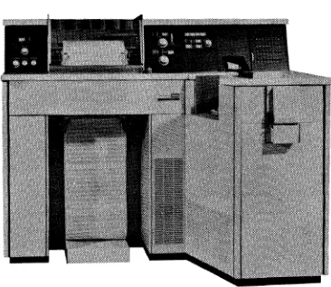
Figure 2·1. UNIVAC 1005 System
The UNIVAC 1005 System (Fig. 2-1) is a low cost, high performance, consolidated data processing system.
The system introduces a central processor which is uniquely capable of being both internally and externally programmed. Existing UNIVAC 1004 connection panels are compatible with the UNIVAC 1005 System. The system contains an Electronic Program Module which can be installed on existing UNIVAC 1004 Systems.
The UNIVAC 1005 System utilizes cor~ storage of either 2048 or 4096 storage locations, with access times of 8 microseconds or 6.5 microseconds, depending on model.
•
Software available with the system includes an assembler, and a report generator, both described in Section 5, PROGRAMMING.
A. SYSTEM MODELS
The UNIVAC 1005 System is available in three models. The models differ in pro-cessing and I/O speeds, and model III includes magnetic tape storage. Characteris-tics of the three models are summarized below.
UNIVAC 1005 MODEL I
BASIC SYSTEM SPEEDS
PROCESSOR B MICROSECOND CORE ACCESS TIME
READER 400 CARDS PER MINUTE
PRINTER 400 LINES PER MINUTE
PUNCH 200 CARDS PER MINUTE
UNIVAC 1005 MODEL II
BASIC SYSTEM SPEEDS
PROCESSOR 6.5 MICROSECOND CORE ACCESS TIME
READER 615 CARDS PER MINUTE
PRINTER 600 LINES PER MINUTE
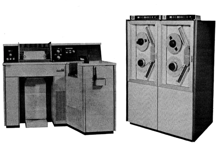
Figure 2·2. UNIVAC 1005 System Model III
UNIVAC 1005 MODEL III
BASIC SYSTEM SPEEDS
PROCESSOR 6.5 MICROSECOND CORE ACCESS TIME
READER 615 CARDS PER MINUTE
PRINTER 600 LINES PER MINUTE
PUNCH 200 CARDS PER MINUTE
MAGNETIC TAPE UNITS UP TO 34,160 CHARACTERS PER SECOND
The UNIVAC 1005 III System includes magnetic tape storage by the incorporation of UNISERVO* VI C Magnetic Tape Units.
Each of the above models is program compatible with its predecessors, and can be expanded with a wide range of peripheral equipment.
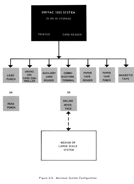
B. SYSTEM CONFIGURATION
OR
c.··.'
. 'OR
I
I
+
MEDIUM OR LARGE SCALE
SYSTEM
The UNIVAC 1005 System is capable of a virtually unlimited variety of system con-figurations. Individual input/output equipment available as part of the system is des-cribed in Section 4, I/O and Communications equipment. The diagram of a maximum sys-tem configuration (Figure 2-3) shows the equipment presently available as part of the UNIVAC 1005 System. Any subset of the above system can be expanded by the addition of any available equipment. Such expansion requires no reprogramming of previous ap-plications.
o
c-3.
CENTRAL PROCESSOR
The UNIVAC 1005 Central Processor performs all logical, arithmetic, and special func-tions; controls the flow of data through the system, and coordinates the operation of all
input/output equipment. The processor contains a magnetic core store which provides storage for all constant, transient, and instruction data during processing. The processor functions under the control of programs, delivered to the machine either as a set of in-structions read into core storage, or as a user-wired connection panel.
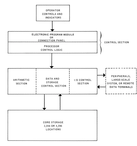
Logically, the central processor consists of six basic elements, as shown in Figure 3-1, Functional Block Diagram. These elements are:
• CORE STORAGE
• CONTROL SECTION
II DATA AND STORAGE CONTROL
• ARITHMETIC SECTION
• I/O CONTROL
OPERATOR CONTROLS AND
INDICATORS
'l1li
,.
ELECTRONIC PROGRAM MODULE OR
CONNECTION PANEL PROCESSOR CONTROL LOGIC
"l1li
,.
II
I I
DATA AND ARITHMETIC I
I STORAGE
SECTION I
I CONTROL SECTION
I
I
....
~'l1li
,.
CORE STORAGE 2,048 OR 4,096
LOCATIONS
I/O CONTROL SECTION
)
C ONTROL SECTION
}
r---I
~!
PERIPHERALS,LARGE'SCALE SYSTEM, OR REMOTE
DATA TERMINALS
I I ~
:
1""-
I I I1... _ _ _ _ _ _ _ _ _ _ _ .J
Figure 3·1. UNIVAC 1005 Central Processor - Functional Block Diagram
After initiation from the operator control panels, data is read into core storage via the I/O control circuits. The data is then processed according to program instructions, which are interpreted by the control section. During processing, data moves through the data and storage control section, the arithmetic unit, and core storage as required by the application. Output data is then delivered to the desired output equipment under program command.
o
c-
A. CORE STORAGEThe UNIVAC 1005 Central Processor is character oriented. Data is stored in the form of six-bit characters. There are 2,048 6-bit locations in each module of core storage. The basic system is expandable to 4,096 characters of core storage. There are 126 locations reserved for Register and controls in the 2K System and 252 in the 4K System. Storage cycle time is 6.5 or 8 microseconds per character. The magnetic core memory provides storage for instructions and data during the performance of programs. There are reserved input/output areas in storage. However, the programmer can modify the sizes of such areas to meet the needs of any program. This allows both a high degree of programming flexibility, and economical usage of storage.
Information is stored in variable length areas called fields. A field is defined as a group of consecutive storage locations whose contents are treated as a unit. Each location within a field can store a six-bit decimal, special, or alphanumeric character. Since fields can be of any length, information units of varying lengths can be stored with equal efficiency.
B. CONTROL SECTION
The main function of the control section is the selection, interpretation and execution of instructions in a program run. In effect, the control unit interprets the programmer's instructions and initiates machine sub-commands necessary to execute each instruction. In performing this task, the control section directs the sequence and type of all opera-tions of the arithmetic, storage, and I/O control elements.
The processor logic control circuits carry out the following cycle of actions as directed by the control module:
1. The Data and Storage Control Section is directed to read a program instruc-tion from locainstruc-tions in core storage designated by a Program Address Counter. The instruction is delivered to an Instruction Address Register, also in core
storage.
2. The Program Address Counter is incremented by an amount equal to the number of characters in the instruction. The Address Counter is now con-ditioned to specify the address of the next instruction.
3. The instruction in the Instruction Address Register is interpreted by the Control Module, which then directs all required processor elements in the execution of the instruction.
4. The above cycle is repeated.
If the connection panel is in use rather than the Electronic Program Module, instruc-tions are not read from core storage, but are ordered directly by connection panel wiring.
C. DATA AND STORAGE CONTROL
The Data and Storage Control Section consists of a six-bit Data Register, through which all data passes going to and from core storage, and of two operand address registers which determine what storage areas will be accessed. The operand address registers are loaded with the specified addresses at the beginning of each operation cycle.
D. ARITHMETIC SECTION
The Arithmetic Section consists of two 6-bit transient registers, an adder, control circuits, and a set of indicators. The unit performs all arithmetic and logical opera-tions, including multiplication and division. The indicators, whose status can be in-terrogated by the program, include:
• Comparison Indicators - less than, equal to, greater than. • Sign Indicators - positive, negative, or zero.
• Arithmetic Overflow Indicator
• Zero digit indicator (for any program specified digit). E. INPUT/OUTPUT CONTROL SECTION
o
The Input/Output Control circuits coordinate program demands for I/O operations with the currect status of the processor and of the requested I/O equipment. Card and paper tape punching are initiated immediately upon program demand, and no interlock of the
Processor or other equipment occurs. Assigned areas in core storage receive input data (~! and accumulate data. These areas are released for other uses when not needed ~ for I/O operations.
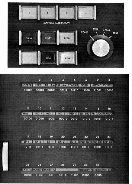
F. OPERATOR CONTROLS AND INDICATORS
Processing controls and indicators appear on the Central Control Panel and Display Panel.
Controls on the Central Control Panel provide for the initiation, interruption and termination of a program run. Four buttons on the Central Control Panel are directly associated with the control section of the processor. Two provide a means for manual alteration of a program in progress.
The Display Panel provides facilities for program testing and monitoring. The Dis-play Panel, located above the card reader, contains indicators relevant to abnormal equipment conditions and provides detailed information concerning central processor operation.
Figure 3·2. Centr al Control Panel; and Display Panel
4. INPUT / OUTPUT AND
COMMUNICATIONS EQUIPMENT
Any UNIVAC 1005 System can be expanded through the use of a wide variety of peripheral equipment. The card reader and printer, supplied with all UNIVAC 1005 Systems, are described in the first portion of this section. The magnetic tape and other facilities available are discussed in subsequent subsections. All peripheral equipment is under direct control of the user program.
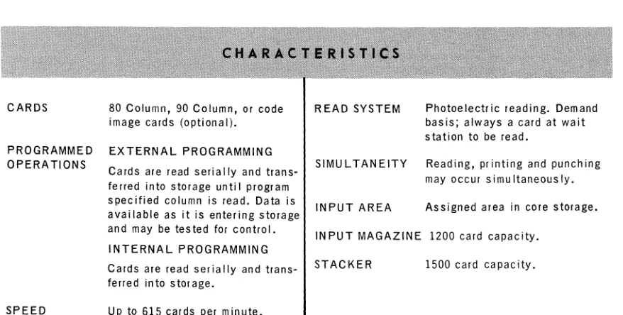
A. STANDARD I/O EQUIPMENT 1. Card Reader
The card reader is located at the right front of the processor (Figure 4-1). Cards are read serially at the rate of 400 or 615 cpm on a demand basis. The cards are read as they pass the read station made up of 12 photo cells. During reading, the card image is transferred to a section of the core storage assigned to card reading. This area of storage is referred to as read storage.
The input magazine at the front of the read section has a capacity of approximately 1200 cards and is angled toward the centrally located operator controls for easy access. The card stacker, located above and to the rear of the input magazine, holds approximately 1,500 cards. A card is fed to the wait section where the direction of travel is altered to allow the cards to pass under the photo cells serially. After the card is read it is deposited "on end" in the card stacker.
o
&
c
c
CARDS
PROGRAMMED OPERATIONS
SPEED
Figure 4·1. Card Reader
80 Column, 90 Column, or code image cards (optional).
EXTERNAL PROGRAMMING
Cards are read serially and trans· ferred into storage until program specified column is read. Data is available as it is entering storage and may be tested for control.
INTERNAL PROGRAMMING
Cards are read ser ia lIy and trans-ferred into storage.
Up to 615 cards per minute.
READ SYSTEM Photoelectric reading. Demand
basis; always a card at wait station to be read.
SIMULTANEITY Reading, printing and punching
may occur simu Itaneous Iy.
INPUT AREA Assigned area in core storage.
INPUT MAGAZINE 1200 card capacity.
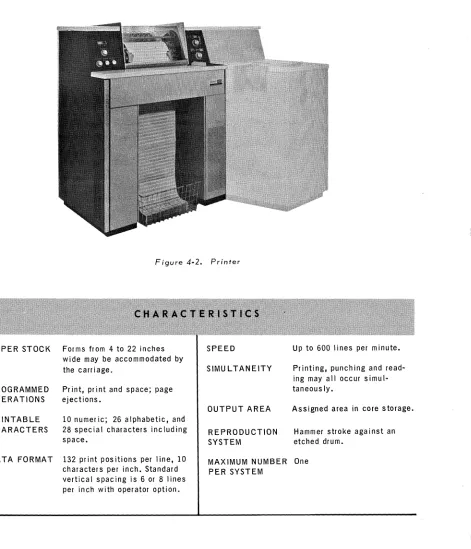
2. Printer
The printer is attached to the left of the processor (Figure 4-2). Printing speeds up to 600 lines per minute may be obtained, with a maximum of 132 print positions per line. Character spacing is ten to the inch horizontally, with an option to the operator of six or eight lines to the inch vertically. Anyone of sixty-three characters may be printed at each of the 132 print locations.
Figure 4·2. Printer
PAPER STOCK Forms from 4 to 22 inches SPEED Up to 600 lines per minute.
wide may be accommodated by
the carriage. SIMULTANEITY Printing, punching and
read-ing may all occur
simul-PROGRAMMED Print, print and space; page taneous Iy.
OPERATIONS ejections.
OUTPUT AREA Assigned area in core storage.
PRINTABLE 10 numeric; 26 alphabetic, and
CHARACTERS 28 special characters including REPRODUCTION Hammer stroke against an
space. SYSTEM etched drum.
DATA FORMAT 132 print positions per line, 10 MAXIMUM NUMBER One
characters per inch. Standard PER SYSTEM
vertical spacing is 6 or 8 lines per inch with operator option.
o
0·)
A
V
~
B. MAGNETIC TAPE
Figure 4-3. UN/SERVO V/ C Magnetic Tape Unit
The UNISERVO VI C Magnetic Tape Unit (Figure 4-3) provides the capability of reading and writing magnetic tape at densities of 200, 556, or 800 characters per inch, with no intermediate conversion steps required.
TAPE Plastic tape in reels up 2400 feet.
TAPE SPEEDS Read/Wr ite Speed 42.7 inches per sec.
Rewind Speed Less than 3 min.
START/STOP Read Start 15.1
TIMES Read Start after
Backspace 10.9
Read Stop 10.9
Write Start 9.3
Write Check 5.8
Write Stop 10.9
Backspace Start
after Read 10.9 ms.
or Write
Backspace Stop 10.9 ms.
*
Transport
Selection 6.0 ms.
*
*
Processor not InterlockedDATA TRANSFER SPEEDS
DATA FORMAT
PROGRAMMED OPERATIONS
200 CPI 556 CPI 800 CPl
8,540 chars. per sec. 23,741 chars. per sec. 34,160 chars. per sec.
Variable blocks of 6 bit characters, lnterblock gap of 3/4".
Read forward, write forward, back· space one block, erase before write, transport select, and rewind.
DATA CHECKING Character parity, longitudinal
par ity, read after wr ite.
I/O AREA Any area of storage designated by
C. PERIPHERAL CARD EQUIPMENT
Figure 4-4. UNIVAC 1001 Card ControlJer
1. UNIVAC 1001 Card Controller
The UNIVAC 1001 Card Controller (Figure 4-4) is a high-speed, multi-purpose machine whose principal function is to arrange card files into groups or sequences required for subsequent processing. It is equipped with two card-input magazines, each capable of feeding cards at speeds up to 1000 cpm. Seven output stackers permit a wide selection as well as matching, merging, and other common collating operations.
The Card Controller includes 256 characters of core storage and a variable sequence of program steps. At the option of the user, any or all information in any card may be selectively stored for one or more cycles and compared as required by the specific application. Thus, the user is not restricted to an arbitrary number of available comparing positions nor to a fixed sequence of operations.
In addition to comparing, the Card Controller provides such processes as adding, subtracting, and transferring of the data entered. Thus the input data can be pro-cessed and manipulated into the form desired for output.
All operations of the Card Controller - card feeding, comparison, information storage, data processing, and stacker selection - are directed by the user through wiring of a removable connection panel.
With a UNIVAC 1001 Card Controller included in the UNIVAC 1005 System, the uni-que abilities of each unit can be shared by the other units toward enhancing the efficiency of a common program. On the other hand, independent programs can be performed by the UNIVAC 1005 Processor and the Card Controller.
c'
..
&
• The Processor, while executing a program not related to that being performed by the Card Controller can call in the Card Controller for a routine or function to supplement the Processor program.
2. Auxiliary Card Reader
CARDS
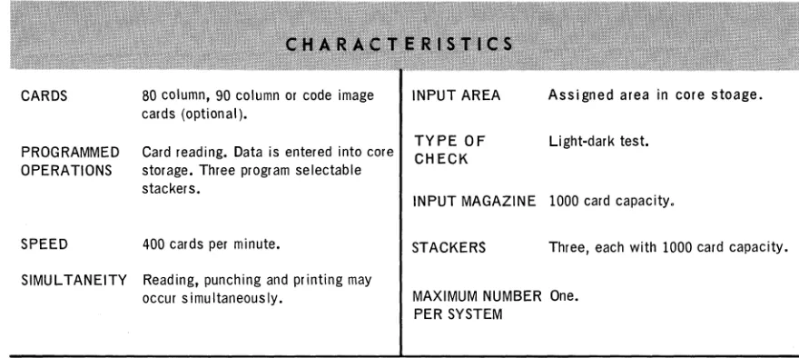
The auxiliary card reader is a free-standing unit which can be cable-connected to a UNIVAC 1005 processor (Figure 4-5).
The maximum card feeding rate is 400 cards per minute, reading 80 or 90 column cards serially. The auxiliary card reader has an input magazine capacity of 1000 cards and three program selectable output stackers, each with a capacity of 1000 cards.
80 column, 90 column or code image INPUT AREA Assigned area in core stoage.
cards (optional).
TYPE OF
Card reading. Data is entered into core Light-dark test.
PROGRAMMED CHECK
OPERATIONS storage. Three program selectable
stackers.
SPEED 400 cards per minute.
SIMULTANEITY Reading, punching and printing may occur simultaneously.
INPUT MAGAZINE 1000 card capacity.
STACKERS Three, each with 1000 card capacity.
MAXIMUM NUMBER One. PER SYSTEM
Figure 4-5. Auxiliary Card Reader
c
o
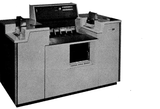
3. Read/Punch or Card Punch
Figure 4-6. Read/Punch
The read/punch unit (Figure 4-6) reads input data from 80 or 90 column cards at a speed of 200 cards per minute, and punches output data into the same cards. Reading and punching are verified by a weighted hole-count check feature. The card punch is identical with the read/punch except that no card reading is performed.
CARDS 80 column, 90 column or code image INPUT/OUTPUT Assigned areas in core storage,
cards (optional) depending on model. AREAS which may be used as working
storage when not in use for input!
PROGRAMMED Read input data from, and punch out- output operations.
OPERATIONS put data into the same cards. Select
output stacker. TYPE OF Reading and punching are verified
CHECK by weighted hole count at the post
SPEED 200 cards per minute whi Ie reading punch station.
and punching.
INPUT MAGAZINE 1000 card capacity.
SIMU L TANEITY Read/Punch functions do not
inter-lock processor; both reading and STACKERS Two, each with 1000 card capacity.
punching can overlap printing,
pro-cessing and reading by the processor. MAXIMUM NUMBER One.
D. PAPER TAPE EQUIPMENT
)
Figure 4·7. Paper Tape Reader - Mounted on Card Reader
1. Paper Tape Reader
The paper tape reader is available as an optional unit (Figure 4-7). It is located
ad-jacent to and in front of the card reader. The unit utilizes a photo-electric read process f"\
and read 5, 6, 7 or 8 channel paper or Mylar* tape. It reads blocks of tape into "~~ magnetic core storage at the rate of 400 characters per second while checking
odd parity.
TAPE 11/16",7/8" or I" Mylar
*
or paperchad tape.
DATA FORMAT 5,6,7, and 8 level codes. 10 frames to
the inch.
PROGRAMMED Read data into core storage.
OPERATION
SPEED 400 frames per second.
SIMULTANEITY Paper Tape reading, Card punching, printing may occur simultaneously.
READ SYSTEM
INPUT AREA
DATA PROTECTION
Photoe lectr ic.
Assigned area in core storage which may be expanded by programmer.
Parity check.
MAXIMUM NUMBER One. PER SYSTEM
C
... /c'
2. Paper Tape Punch
The paper tape punch (Figure 4-8) is available as an optional unit. It is located on the right front of the card punch or read/punch. 5, 6, 7 or 8 level tape can be punched at a speed of 110 characters per second.
TAPE
DATA FORMAT
PROGRAMMED OPERATIONS
SPEED
11/16" or 1" paper or Mylar* tape.
5, 6, 7 and 8 level codes. 10 frames to the inch.
Punches blocks of data into tape.
110 characters per second.
SIMULTANEITY Paper Tape punch i ng over I aps car d
reading, printing and processing.
PUNCH SYSTEM Die punch, produces chad tape.
OUTPUT AREA Assigned area in core storage.
Area may be used as working storage when not in use for output.
MAXIMUM NUMBER One.
PER SYSTEM
E. COMMUNICATIONS
The Data Line Terminal available with the UNIVAC 1005 System gives the user complete freedom in selection of transmission codes and formats. Remote terminals can be:
• Other UNIVAC 1005 Systems
• Large scale systems such as the UNIVAC 490 Series or 1107/1108 systems.
Communications are via leased or exchange facilities. Interface with telephone systems is via Bell Data- Phone data sets.
When programmed externally, the Univac 1005 System can provide these additional capabilities:
• Transmission rates up to 40,800 bits per second, using Telpak, Type C* facility. • Communication with Digitronics Dial-o-verter** Terminals.
*T~adema~k of Ame~ican Telephone and Teleg~aph Company.
'*T~adema~k of Digit~onics Co~po~ation.
i
c
C';
"5. PROGRAMMING
The UNIVAC 1005 System is a stored program processor. Program instructions are delivered to the machine as coding punched into cards. The instructions on the cards are read into core storage, and the processor examines, interprets, and executes these instructions (F igure 5-1).
OPERATOR
CONTROLS
ELECTRONIC PROGRAM
MODULE
PROCESSOR
t
l
( . PROGRAM
INSTRUCTIONS
CORE STORAGE OUTPUT DATA
(NPUT DATA
Figure 5-1. Stored Program
A UNIVAC 1005 instruction occupies either five or seven locations in core storage. The first character is the operation code, and specifies the type of operation to be performed. The remaining characters designate the addresses of the operands, or, in the case of I/O operations, the exact nature of the operation being performed.
Since programming in machine language requires constant reference to tables of operation codes, address codes, and absolute addresses, it is highly desirable that these tasks be performed by the processor rather than the programmer. The UNIVAC 1005 System is pro-vided with two programs which perform the above and many other programming functions. These are the UNIVAC 1005 Assembly Program and the UNIVAC 1005 Report Program Generator.
A. UNIVAC 1005 ASSEMBLY PROGRAM
The UNIVAC 1005 Assembly Program, designed to operate with any UNIVAC 1005 configuration, is a powerful programming tool, easy to learn and to use. The as-sembly program accepts, as input, symbolic coding written in UNIVAC 1005 Asas-sembly Language. The program produces as output a directly loadable object program, a listing of the source program, and a parallel listing of the resulting object code.
Instructions in UNIVAC 1005 Assembly language are written in the form of mnemonics; that is, two-character codes which suggest the name of the operation ordered. These names parallel those used in UNIVAC 1004 programming, making it unnecessary for the programmer to learn a large number of new terms. The basic instruction repertoire includes:
10 Transfer and Compare instructions
8 Arithmetic instructions, including multiply and divide 4 Editing instructions
7 Jump instructions
7 Basic, and over 30 functional Input/Output Instructions 3 Control instructions
The UNIVAC 1005 Assembler permits the use of labels, freeing the programmer from the need for constant reference to absolute addresses. Labels can be incremented, and the programmer can order left or right justification of data entered in the label field.
The assembly directives available with the UNIVAC 1005 Assembler Program allow the user to direct the way in which the actual assembly is performed. These direc-tives are summarized below.
Define Location Counter - permits the user to start at any storage location when assigning instructions. The assembler determines the starting location if not defined by the user.
Define Area - 1) reserves working storage.
2) provides a base on which labels may be defined. Define Subfield - permits definition and labeling of subfields.
c
c
Define Indirect Address - provides a means of developing and referencing indirect
addresses.
Define Constant - permits the definition and labeling of masks, constants, and
tabular information.
Define Entry Point - permits control of entry to and return from overlaid program
segments.
End - permits orderly termination of assembly.
During assembly, the assembler indicates with the program listing any of the following errors which may have occurred:
• Illegal mnemonics • Duplicate labels • Undefined labels
B. REPORT PROGRAM GENERA TOR
The report program generator for the UNIVAC 1005 System is designed to allow the user to concentrate his efforts on the problem rather than the system processing his problem.
Essentially, the user describes his problem in terms that are familiar to him. For ex-ample, he describes the card in terms of the field on the card, he compares these fields
to cause Major, Intermediate or Minor breaks.
The user describes his counters and totals or cross foots them during these control
breaks. If he wishes to punch or print, he does not have to redescribe what is required in the punch or print area. He describes the output format once, when he wants to output it, he merely says PUT. The Report Program Generator will form the record for him.
The 1005 Report Program Generator allows the user another facility. It allows him to use the same name for a field when describing input, work area, or output. Only a prefix must be added; for example: I-Rate, W-Rate or O-Rate are all the same except that one is for input, one for the work area, and one for the output. (The hyphen is not employed, it is only used for clarity).
6. INSTRUCTION REPERTOIRE
MNEMONIC INDICATOR INDIRECT LENGTH
OPERATION
CODE SENSITIVE ADDRESSING (CHARS)
TA NO YES 7 (OPl) ... OP2
TD NO YES 7 (OPl)+-OP2
TC NO YES 7 (OPl)+-OP2
TK NO YES 7 KK +-OP2
TN NO YES 7 (OPl)+-OP2
TR NO YES 7 T (OPl)+-OP2
TX NO NO 5 (OPl)+-xRe2
CA YES YES 7 (OPl) : (OP2)
CM YES YES 7 (OPl) : (OP2)
CN YES YES 7 (OPl) : (OP2)
CK YES YES 7 KK : (OP2)
AD YES YES 7 (OPl)+ (OP2).-QP2
AM YES YES 7 (OPl)+(OP2~OP2
DV YES NO 7 (OPl).;-(OP2~P3
ML YES NO 7 (OPl)x (OP2)- X
MU YES NO 7 (OPl) x (OP2)- X
SM YES YES 7 (OP2)-(OPl)-OP2
SU YES YES 7 (OP2)- (OPl)- OP2
AK YES YES 7 K + (OP2)- OP2
CC YES NO 5* KK + (OP2~OP2
EL YES NO 7 [K2VOP2; K,/\OP2]
-OP2
ES YES NO 7 Kv(OP2)-OP2
EE YES NO 7 K/\(OP2)- OP2
ED NO YES 7 (X-Mask) (OPl)-OP2
SC YES NO 5
JC YES NO 5 IF I=OPl, OP2 MSL-CC
JK YES NO 7 IF K=(OP2 LSL), OP2 MSL-CC
JL NO NO 7 IF DD=-l7' 0, OP2 MSL-CC
IF DO,= + or 0, NI
JR NO NO 7 OPI-OP2 LSL, OP2 MSL-CC
JT YES NO 5 IF C<, OPl-CC
IF C=, OP2 -CC
IF C>, NI
J NO NO 5 OPl- CC
JI YES YES 7 (OPl)-CC
GC NO NO 7
RT NO NO 7
WT NO NO 7
RD NO NO 7
SD NO NO 7
RF NO NO 7
SF NO NO 7
DESCRIPTION
Transfer Ascending
Transfer Descending
Transfer Clear
Transfer Constant
Transfer Numeric
Translate (optional feature)
Transfer to Reg. X
Compare Alphanumer ic
Compare Magnitude
Compare Numeric
Compare Constant
Add Algebraic
Add Magnitude
Divide
Multiply Long
Multiply
Subtract Magnitude
Subt ract Algebraic
Add Constant
Count
Edit Logical
Edit Super impose
Edit Erase
Edit Mask
Set Conditions
Jump Condition
Jump Compare Jump Loop
Jump Return
Jump Test (Compare < , =, > )
Jump
Jump Indirect
General Commands
Write Magnetic Tape
Read Magnetic Tape
Receive DLT
Send DLT
Receive Interface
Send Interface
\ ;lJ
o
GENERAL I/O INSTRUCTION: AVAILABLE SUBINSTRUCTIONS
READ CARD PUNCH TEST
READ CARD (AUXILIARY READER) PUNCH STACKER SELECT
SELECT READ STACKER PUNCH PAPER TAPE
READ CODE IMAGE PUNCH CODE IMAGE
READ PAPER TAPE SET ERASE MAGNETIC TAPE
PRINT BACKSPACE MAGNETIC TAPE
SPACE 1 OR 2 REWIND MAGNETIC TAPE
SKIP 1, 2, or 4 SET REQUEST TO TRANSMIT
PUNCH HOLD OR CLEAR READ/PUNCH UNIT
C'
JUMP CONDITION INDICATORS SET INDICATORS
FORM OVERFLOW ODD PARITY
ARITHMETIC OVERFLOW EVEN PARITY
SENSE INDICATORS 1 AND 2 SENSE INDICATORS 1 AND 2
AL TERNATE HOLDS 1 AND 2 SENSE INDICATORS 1 AND 2 (RESET)
INTERRUPT SERVO 1,2
UNIT ALERT INDICATOR 1 AND HALT
PARITY ERROR INDICATOR 2 AND HALT
..
POSITIVE RESULTZERO RESULT
•
NEGATIVE RESULT
END OF TAPE
INVALID CODE CHECK
w
....
ZONE NUMERIC CARDlID",
« BITS BITS
CODE
I - l :
! u
'"
XY 84210..
Space 00 0000
-1 00 0001 X-5-B
- 00 0010 X
0 00 0011 0
1 00 0100 1
2 00 0101 2
3 00 0110 3
4 00 0111 4
5 00 1000 5
6 00 1001 6
7 00 1010 7
B 00 1011 B
9 00 1100 9
\
00 1101 0-6-B; 00 1110 X-6-8
[ 00 1111 Y-5-B
CHARACTER SET
w w
;;'" ZONE NUMERIC CARD
....
lID'" ZONE NUMERICBITS BITS BITS
0« I-l: zu
"'
0.. & : ? A B C D E F G H I # < =BITS CODE 0«
I - l :
:!:u
XY 8421
'"
XY 84210..
01 0000 Y
,
10 000001 0001 5-B
*
10 0001 01 0010 Y-3-B $ 10 001001 0011 Y-O ! 10 0011 01 0100 Y-l J 10 0100 01 0101 Y-2 K 10 0101
01 0110 Y-3 L 10 0110
01 0111 Y-4 M 10 0111
01 1000
y-s
N 10 100001 1001 Y-6 0 10 1001
01 1010 Y-7 P 10 1010
01 1011 Y-B Q 10 1011
01 1100 Y-9 R 10 11 00
01 1101 3-B ( 10 11 01
01 1110 Y-6-B @ 10 1110
01 1111 Y-7-B 1'1 10 1111
UNIVAC 1005 CHARACTER CODES
80 COLUMN SYSTEM
w
CARD ;; '" ZONE NUMERIC CODE 0( 0( I - l : BITS BITS
zu
"'
XY 84210..
7-B f. 11 0000 X-4-B % 11 0001
X-3-B , 11 0010
X-O + 11 0011
X-l I 11 0100
X-2 S 11 0101 X-3 T 11 0110
X-4 U 11 0111
X-5 V 11 1000
X-6 W 11 1001
X-7 X 11 1010
X-B Y 11 1011
X-9 Z 11 1100
0-5-B II 11 1101 4-B > 11 1110
X-7-B ) 11 1111