Wireless Power Theft Identification and Auto
Informer to the Local Substation
Lediya Jacob1, Nayana M S1, Noushiya A1, Rukhiya Fahmidha1, Unni M R2
U.G. Students, Department of Electrical and Electronics Engineering, Nehru College of Engineering and Research
Centre, Thrissur, Kerala, India1
Professor, Department of Electrical and Electronics Engineering, Nehru College of Engineering and Research
Centre,Thrissur, Kerala, India2
ABSTRACT:It is designed to develop an auto power theft identifier system, which is a very scope full subject in this power-scarce-world. Here there are two Energy Meters. One at home and other at supply junction box. We use GSM communication between the office and home. A microcontroller based system is the major control and co-ordination part of this system. The pulse sequences from EB meters which are varying according to the load inputted to the microcontroller. The microcontroller calculates the consumption unit of each meter and compares them continuously via the program load in it. If there any difference in the readings of 2 meters. The controller decide it as an electricity-theft and make an automatic SMS to the EB office via the GSM modem interfaced with this system.
KEYWORDS: GSM, Power Theft Identification, AT89S52 Microcontroller, Auto informer to the local substation, LCD
I. INTRODUCTION
The electricity is needed to be protected for efficient power delivery to the consumer because electricity is indispensable to domestic and industrial development activity. There are two types of losses technical and Nontechnical losses. Every year the electricity companies fare the line losses at an average 20-30% according to power ministry WAPDA Company’s loss more than 1.25billion. T&D losses have been a concern for the Indian electricity sector.
Since these have been very high when compared with other developed countries. The present T&D losses including unaccounted energy are about 30% and there is need to reduce these losses through efficient management the best operation and maintenance practice of the transmission and distribution. When we talk about T&D losses it also includes the theft of electricity, although it is the part of commercial loss but there is no way to segregate theft from the T&D losses.
In practice, we know the energy billed and the input energy the difference between these two is T&D losses obviously the theft is included in this loss. SERC, Mop also ask to segregate T&D loss and commercial loss but nobody is able to tell how these losses can be segregated, as theft (the part of commercial loss) is embedded with T&D Electricity theft is at the centre of focus all over the world, but electricity theft in India has a significant effect on the Indian economy. The loss on amount of theft is reflected in ARR of the electricity company. Thus these costs are routinely passed on to the customers in the form of the higher energy charges .Electricity power theft takes place in a variety of forms and thrives with the support of people from different walks of life: utility staff, consumers, labour union leader, political leaders, bureaucrats and high level utility officials. The problem challenging power utilities worldwide is the electricity, in other words using electricity from utility company without the company’s consent.
II. RELATED WORK
The power theft monitoring is an important research in electric power system and electricity stealing prevention became a big problem to the electricity. Electricity stealing is a long term problem; however each power supply department has me huge investments of manpower and material, the phenomenon of defending stealing electricity has increased and not abated and the method of electricity stealing is continuously improved. The behaviour of electricity stealing not only makes the power industry suffering huge financial losses but also threatens the main power supply security and reliability
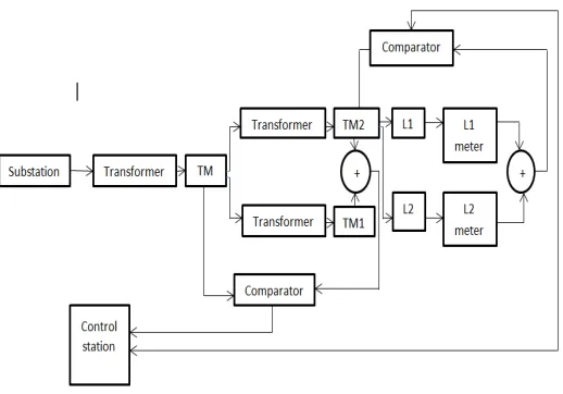
Figure 2: Block diagram of the proposed stealing method.
time is record, the beginning time of electricity stealing and alarm information are transmitted to the field man through GSM network.
BLOCK DIAGRAM
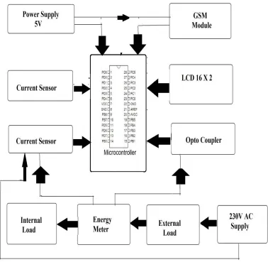
Figure 3 shows the block diagram of wireless power theft identification and auto informer to the local substation. The various components in the system are described below.
Figure 3: Block diagram
Hardware Description
Transformers
transformer operates on the principals of “electromagnetic induction”, in the form of mutual induction. The transformer used here is a step-down transformer so that it can be directly convert 230v AC to 12v AC
Microcontroller
The microcontroller is used to compare the load. Atmel 89S52 is the controller used for this purpose and it also provides a provision for GSM module and in built ADC.
Relay
Relays are components which allow low power circuit to operate high current application circuits. It is an electrically operated switch and is used where it is necessary to control a circuit by a low-power signal with complete electrical isolation between control and controlled circuits, or where several circuits must be controlled by one signal. The relay used here is an electromagnetic type which operates in 12v.
GSM Modem
A GSM modem is a specialized type of modem which accepts a SIM card, and operates over a subscription to a mobile operator, just like a mobile phone. Here the purpose of GSM modem is to send the electricity theft details to the local substation. It requires a SIM card to send the message.
Voltage Regulator
Voltage regulators are three-terminal devices that provide a constant DC output voltage that is independent of the input voltage, output load current, and temperature. IC voltage regulators are used in power supplies that hold their output voltage constant over a wide range of load variations.
Display Unit
Liquid Crystal Display (LCD) is used as the display unit. This is a basic 16 character by 2 line display is black text on the green background.
Power supply
The microcontroller and associated circuitry requires 5Vsupply while the relay requires a 12 V supply. A single 12Vadapter connected to the mains produce DC 12V output usable for the relay and this voltage is further passed through a positive fixed voltage regulator IC 7805 resulting in a 5V DC output usable for the microcontroller and other logic circuitry.
III.CIRCUITDIAGRAM
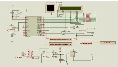
Figure 4 refers the complete circuit diagram of theft wireless power identification and auto informer to the local substation with sufficient rating as we used.
Fig 4 Circuit Diagram of wireless power theft identification and auto informer to the local substation
Circuit Diagram Description
The system consists of two digital energy meters of which one meter reads the actual load and other reads the theft load. The power supply circuit description: The 230v AC supply is step downed to 12v AC using a core type step down transformer and then connected to a full wave bridge rectifier (four IN4007 diodes) which converts it to 12v DC. The ripples are eliminated through 1000 microfarad capacitor connected parallel. And a 7805 voltage regulator is used to get a 5v supply.
Each load is connected with a relay and energy meter. A crystal oscillator is connected parallel to the 18 and 19 pins of microcontroller in order to synchronising the frequency of microcontroller with the frequency of GSM modem. Crystal oscillator sets the frequency to 11.0592MHZ. The controller and LCD require a DC operating voltage of 5V while the relay and GSM operate at a DC voltage ranging from 9V to12V.The controller is programmed in such a way to send a low signal to relay when the difference of two energy meter readings exceeds 2 units. Normally the relay will be latched initially and on receiving a low signal from microcontroller the relay will be de-energized and becomes open thus interrupting the supply. Thus the load cannot be operated even if the manual switch is closed. At the same time the GSM sends a message to the control room about the theft action. Whenever the theft detects, it automatically cut the load section.
Connections
The AT89S52 is a low-power, high-performance CMOS 8-bit microcontroller with 8Kbytes of in-system programmable Flash memory.It provides the following standard features: 8K bytes of Flash, 256 bytes of RAM, 32 I/O lines, Watchdog timer, two data pointers, three 16-bit timer/counters, a six-vector two-level interrupt architecture, a full duplex serial port, on-chip oscillator, and clock circuitry. In addition, the AT89S52 is designed with static logic for operation down to zero frequency and supports two software selectable power saving modes. The Idle Mode stops the CPU while allowing the RAM, timer/counters, serial port, and interrupt system to continue functioning. The
Power-XTAL2 18 XTAL1 19 ALE 30 EA 31 PSEN 29 RST 9 P0.0/AD0 39 P0.1/AD1 38 P0.2/AD2 37 P0.3/AD3 36 P0.4/AD4 35 P0.5/AD5 34 P0.6/AD6 33 P0.7/AD7 32 P1.0/T2 1 P1.1/T2EX 2 P1.2 3 P1.3 4 P1.4 5 P1.5 6 P1.6 7 P1.7 8 P3.0/RXD 10 P3.1/TXD 11 P3.2/INT0 12 P3.3/INT1 13 P3.4/T0 14 P3.7/RD 17 P3.6/W RP3.5/T1 1615 P2.7/A15 28 P2.0/A8 21 P2.1/A9 22 P2.2/A10 23 P2.3/A11 24 P2.4/A12 25 P2.5/A13 26 P2.6/A14 27 U1 AT89C52 D 7 1 4 D 6 1 3 D 5 1 2 D 4 1 1 D 3 1 0 D 2 9 D 1 8 D 0 7 E 6 R W 5 R S 4 V S S 1 V D D 2 V E E 3 LCD1 LM016L Q1 BC547 R9 10k RL1 12V C1 27p C227p 11.0592MHZ CRYSTAL R10 8.2k C3 10uf RESET
12 V DC
230 V R X D R T S TX D C T S
GSM MODEM( SIM300 )
EB Measure Sensor 1
R11 10k R1 10k R2 10k R3 10k R4 10k R5 10k R6 10k R7 10k R8 10k
EB Measure Sensor 2
TR1 TRAN-2P2S D1 DIODE D2 DIODE D3 DIODE D4 DIODE C4 1000u V I 1 V O 3 GND 2 U2 7805
230 v AC 12 v AC
5 v D C 1 2 v D C
Copyright to IJIRSET DOI:10.15680/IJIRSET.2016.0504201 6167 down mode saves the RAM contents but freezes the oscillator, disabling all other chip functions until the next interrupt or hardware reset.. A crystal oscillator is used to generate clock signals to the controller. It is connected to pin no. 19 and 18 of the controller which generates clock signals. Digital pins PD0 to PD.7 are configured as output and all the output devices like LCD and GSM are interfaced to this port. The relay is connected to third pin of port 3 and GSM transmitter, receiver are connected to first and second pin of port 2. All the loads are connected to the port 3 through a relay which is supplied with a 12V supply. A BC 547 transistor is insisted serially in order to control the switching action of relay system. It is also possible to use internal oscillator of the controller unless the ADC pins are used. In order to view the message displayed by GSM, a virtual terminal is used. A 16x2 dot matrix LCD gives a visual indication of the two energy meter reading and other details. For LCD display 8 bits of address lines are connected to the controller. RESET pin is connected to the power supply so that the controller works continuously. The controller can be reset by applying a logical low signal to RESET pin. Whenever a high signal is applied to the base of the transistor, the transistor act as a closed switch and energizes the coil of the relay which in turn latches the relay contactors. A freewheeling diode or a flywheel diode is connected across the relay coil to protect the collector terminal of transistor from the back emf of the relay coil.
IV. EXPERIMENTAL RESULTS
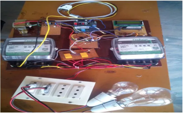
Figure: 5 represent the completed system of theft wireless power identification and auto informer to the local substation. It is demonstrated as connecting the load (200+5 watt bulbs) in the input side of the second energy meter.
Figure 5: Completed system for wireless power theft identification and auto informer to the local substation
V.CONCLUSION
In developing countries electricity theft is a common practice especially in remote areas, as they do not pay utility bills to a government company in case of electricity and gas as well. To solve these problem governments must think of an idea to provide help in terms of subsidy to manage this issue. With this system the service provider can collect the bill any time with a single message. The data collection and manipulation task becomes fast and easier. Any modification can be made to the code in less time. Changes in rate or unit calculation can be done very effectively.
REFERENCES
[2] S Anusha, M Madhavi, R Hemalatha, “Detection of Power Theft Using GSM.”, International Journal of Advanced Research Trends in Engineering and Technology(IJARTET)Vol.1, Issue 3, November 2014.
[3] Seshapu Prasad, D Suneel, “Proximity Sensor Based Security Lock and Theft Detection.”-International Journal of Science Technology and Management Vol. No.4, Issue No.12,December 2015
BIBLIOGRAPHY
Mr.Unni M R, Assistant professor, has obtained his B.E degree from Anna University, Chennai and M.E degree from Anna University, Tirunelveli in 2009 and 2011 respectively. He is currently serving as Assistant professor in Nehru College of Engineering and Research Centre, Thrissur, Kerala, India. He has 5+year of teaching experience to both undergraduate and postgraduate students. Mob: +919400448671,
Lediya Jacob, UG Student, Dept. of EEE, Nehru College of Engineering and Research Centre, Thrissur, Kerala, India.
Nayana M S, UG Student, Dept. of EEE, Nehru College of Engineering and Research Centre, Thrissur, Kerala, India.
Noushiya A, UG Student, Dept. of EEE, Nehru College of Engineering and Research Centre, Thrissur,Kerala,