Prediction of Wear Depth at Near-Distant Future from the Present Depth in the Steam
Generator Tubes of the Nuclear Power Plants
C. Y. Park1), Y. S. Lee1), T. S. Kim1), C. S. Lee1),
1) Korea Electric Power Research Institute, Daejon, Korea
ABSTRACT
This paper is concerned with the prediction method of tube wear in steam generators of nuclear power plants. The proposed method can predict the growth of tube wear using the material constants, obtained inversely from Engel’s impact law or the Archard wear equation, measured tube wear depth and time, based on the fuel cycle. The growth of wear depth until the next fuel cycle from the time of depth measurement (previous fuel cycle) is predicted using the material constant assuming the material constants is not varied for this period. The predicted wear depth using the material constants found inversely is compared with the results obtained from measurements. Proposed method was also applied for SG tubes under the condition of an off-design condition, such as operating in reduced temperature. The results show that predicted wear depth envelops the measured depth. It can be concluded that the methods employed in the present paper can be applied to the prediction of wear depth from a given status of wear at the present time in the near-distant future of S/G of nuclear power plants.
KEY WORDS: Measured Wear Depth, Steam Generator Tube, Near-distant Feature, Wear Prediction, Archard Wear
Equation, Engel’s Impact Law, Cylindrical Contact.
INTRODUCTION
It is well known that a contact area is deformed and worn when the components of a machine and a structure contact each other and a small relative motion or an impact takes place for a long duration. Waterhouse[1] reviewed papers on a wide range of fretting wear. Engel[2,3] performed a literature review regarding impact wear. Hence the detailed literature associated with fretting and impact wear may not necessary to describe in this paper. The present paper is concerned with the investigation of tube wear in steam generators (S/G) of nuclear power plants. Tubes of the primary side are subjected to vibratory motion caused by the secondary side fluid/solid interaction. This vibratory motion causes impact and sliding against the support structure or anti-vibration band. The motion of the impact and the sliding causes tube wear if the motion continues for a long duration. If the tube thickness decreases to a certain limited value, then the tube wear will impede structural integrity. The tubes in S/G are inspected every fuel cycle using eddy current tests. If the results of inspection exceed a certain limit in a percentile of the tube thickness, the tubes are plugged. Hence, the prediction of wear is an important factor in a view of maintenance and control of S/G tubes. Operating conditions or the relative structural arrangements between the tubes and support in the secondary side are varied if a plant is operated for long duration. Hence it is not practical to predict the tube wear at the initial time over a long period if the life of plant and its fuel cycle are considered. The present paper proposes a method to predict tube wear using the material constant
c
, obtained inversely from Engel’s impact law, measured tube wear depth and number of impacts, based on the fuel cycle[. The growth of wear depth until the next fuel cycle from the time of depth measurement (previous fuel cycle) is predicted using the material constant assuming the “c
” value is not varied for this period. The predicted wear depth using the material constantc
found inversely is compared with the results obtained from measurements. The results show that the predicted wear depths envelope the measured depth. This is expected since the predicted depths are obtained using the maximum gap velocity, which is resulted in to the maximum tube displacement and initial impact velocity. Through the investigation, it can be concluded that wear depth or volume of tubes in the near-distant future of S/G of nuclear power plants can be approximately predicted using the material constant obtained from known present wear status and the impact law[1].Transactions of the 17th International Conference on
Structural Mechanics in Reactor Technology (SMiRT 17)
Prague, Czech Republic, August 17 –22, 2003
FORMULATION OF IMPACT WEAR PREDICTION
Assumption and Prediction Method
The purpose of the investigation of the paper was to find the wear depth of S/G tubes in a nuclear power plant. Since the tubes occupied wide ranges in the S/G, it makes it difficult to estimate the wear depth of all the tubes in the steam generator. Hence, only the tubes in a specific location of the S/G are considered. The flow characteristics that cause vibration of the tube and impact against the support structure surrounding the tubes are found previously using on thermal hydraulic analysis program. The impact model for the cause of wear was established by Engel[2,3] and is modified slightly in order to predict wear in the near-distant future from the known wear status at the present time.
Tube wear is considered when a cylindrical tube collides against a plane corresponding to a support structure. In this case the principal curvatures of the tube are the tube radius and on infinitely large curvature. The contact area between the tube and the target assumed to be a plane is considered as a rectangle. The problem of impact, in general, is treated as a dynamic problem considering interactions between the projectile and target even through the present analysis neglects the dynamic behavior in order to simplify the problem. Timoshenko[4] justified neglecting this dynamic behavior. Hence, the responses of the projectile and target are considered to be a static problem and they can be found as a Hertz contact problem. The employed assumptions are neglecting the dynamic responses of the both projectile and target, the solution of the Hertz contact problem can be used, and the mechanical properties ( E, Young’s modulus, ν, Poisson ratio) are identical while the mass/unit length of the projectile is very small compared with that of a target. The present problem is concerned with an estimation of the S/G tube wear surrounded by secondary water. The tubes are vibrating due to fluid motion and the vibration of the tubes causes collision against support structures. If this motion continues for a long period the tube is considered to deform and is worn. The wear depth caused by an impact is estimated by modifying the existing results[1,2] in following section. The wear depth of the tube is predicted in the near-distant future from the known present wear status. The results obtained in next section are compared with the measured wear depth of tubes in the nuclear power plants.
Impact Force by Flow Induced Vibration
The tube vibration associated with the heat exchanger such as S/G is investigated by Connors[5,6]. The displacement of a tube excited by fluid motion is found using the results of Connors. The effect velocity of a tube can be found using the result of
( )
[
] ( ) ( )
( )
[
] ( )
∫
∫
= x
x
g
eff
dx x M x M
dx x x v x v
0
2 0 0
2 2 0
φ φ ρ ρ
(1)
The notations are given separately. The gap velocity vg in S/G secondary side is the velocity between the tubes and is given as
(
)
{
}
ag p p d v
v = − (2) The critical velocity (Connors, 1977 and 1980; Heilker and Vincent, 1981), vcr is defined as
[
2]
12 00 d
m d Kf
vcr= n δ ρ (3)
(
C d v2)
sin t 2g.F = F ρ g ω (4)
Assuming the tube is a beam with given constraints, the maximum displacement of tube is found using Eq. (5),
(
)
(
)
2 2 0 2 2
1 2
n g m
f
g v m d C
C ρ
δ = . (5)
,where C1 and C2 are determined using the constraints of the beam. The values of C1 and C2 are found under the condition of a fixed-support beam in the present calculations. The displacement of the tube is considered as
t
x=δmsinω , where ω is the first mode of the tube and the lowest frequency contained in the fluid is much less than that of tube. Hence δm can be considered as a static deflection of the beam. The velocity amplitude is:
ω δm
v= (6)
Eq. (6) is an initial impact velocity of the tube. Through Eqs.(1) to (6) the responses of the tube caused by fluid motion in the S/G secondary side are found. The next section finds wear depth due to impact against support structures, including an anti-vibration band.
Derivation of Contact Mechanics Equation by Impact
It is well known that tube wear is observed in the S/G and causes an initial failure when two bodies collide together or are moving relatively with infinitesimal displacement for a long duration. Spherical and cylindrical impact wear are described by Engel[2]. A cylindrical impact problem is described, which is based on a Hertz contact solution [4]. When a cylindrical contact problem is treated using the Hertz contact solution, the first kind of elliptical integration is involved and is indeterminate for a cylindrical body. However, Engel [1] performed an analysis using a momentum-impulse relation including the coefficient of restitution instead of this integration. The complete elliptical integration is approximated using the integrated value until θ=89.9833° instead of θ=90°, as in the present calculation. Impact loads/unit length the maximum contact stress, qc and half width of contact width, bc are found through existing solutions [4], assuming impact mass is very small compared with that of the target and both material properties are identical. Through the derivation static responses are obtained when a load q is applied to cylinder. The maximum contact stress is also obtained, which is followings:
(
)
2 1
2 1 2 1
2
1 1
2 2
+ +
= ∆ =
K K R R
R R q b
qc c
π
π (7) where, the impact load per unit length is given by
) 3 . 0 , (
) 1 ( 2 ) (
1 2
2 1
2
= = =
− ′ =
ν δ ν π
E E E
E
K K q
(8)
l p q l
p
bc =
∆
= 2 ,
2 1
π . (9)
(
) (
)
{
2R1R2 R1+R2}
(K1+K2) =∆ π ,
− + − =
+
2 2
1 2
2 1
1 1
1
E E
K
K ν ν
π (10)
,where the approach distance of two contact bodies is given[4,7,8] followings;
q E E
K K
−
+ − ′ =
2 2 2
1 2
1 1
1 ) (
2 ν ν
π
δ (11)
′= −
′ − =
′
∫
2 2 20 2 , 1
sin 1
1 )
( d K b a
K K
K
π
θ
θ (12)
The value of K′ for the cylindrical projectile is 1 and the upper bound of the integration is approximated by
o
9833 . 89 ~
θ instead of θ =π 2. The impact load is found for a spherical body and the responses of the colliding
cylindrical body(tube) against a plane are found using a similar method described in a previous paper [2,4,9]. The approaching velocity can be found from the motion of equation of two bodies, and the contact duration time of a cylindrical body also can be found from Eq.13.
( )
= = −=
∫
∫
t c c cx dx
x v
dt
δ δ δ
δ π δ 1
0 2 12
0 2 ,
1 1
*
(13)
Finally the contact duration time is expressed by
v
t π δc
2
*=
.
The quantities, q, bc, qc and
*
t are found using above equations respectively substituting the values E=E1=E2,
3 . 0 =
ν , R1 and R2→∞. The value of R1 is the tube’s outside radius, 0.375in. These quantities are expressed in
terms of unit length of mass, m, Young’s modulus, E and initial impact tube velocity. The values of q, bc, qc
and t* are given as
(
)
(
)
(
)
( )
1 12 *4 1 2 2 3
4 1 1 2 2
2 1 2
22 . 5
2293 . 0
83574 . 0
301 . 0
− −
−
= = = =
mE t
R mv E q
E mv R b
Emv q
c c
(14)
However the radius curvature of the worn surface is varied depending on the progress of tube wear in the region of
c
c b b
b ≤ ≤
− . Hence the worn surface should pass through the points bc and −bcwith curvatures different from the original radius of tube. Engel[3] introduced a new parameter, λ, which is the ratio of the original tube radius to the worn radius of curvature, λ=R1 R.
It is clear that infinitely many radii of worn curvatures passing the two points of contact width can be considered. However, the radius of curvature λ to satisfy Engel’s wear law should be unique. Engel’s impact law[2] is given as;
c c b
q KN
W = 3 . (15)
The wear volume per unit length, W in Eq. (15) can be reduced to a differential equation (with respect to N and λ) which will be shown later. If λ to satisfy Eq. (15) is found, Eq. (14) can be expressed in terms of the tube radius and λ. Wear volume or wear depth can be found from the geometry of the worn shape.
An Estimation of Wear Volume or Depth Caused by an Impact
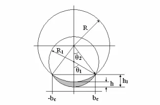
When a tube collides with structures, it is assumed that wear takes place on the tube side. The wear depth and wear volume is found from the geometry shown in Fig.1, assuming the cross section of the worn tube is uniform in the axial direction. The wear depth, h, and volume, W, per unit length are shown as
(
)
(
1)
.2 , 1
2 1
3
1 2
λ
λ = −
− =
R b W R
b
Fig. 1 Configuration for contact model.
(a) Cross-sectional area (b) For measured wear
Fig. 2 Cross-sectional area configuration for cylindrical contact
However, the actual shape of the worn tube is observed as shown in Fig. 2. The maximum wear depth is varied linearly in the axial direction with slope 1.5° and the final result is a uniform depth in the axial direction. It is denoted as a wedge type wear for the former shape because the side view of the wear depth resembles a wedge, while the shape of uniform wear depth through the axial direction is called rectangle-type wear. The wear volume is found using the measured wear depth and Fig. 2(a) and (b):
( )
=
− =
− =
o
5 . 1 tan
type) (wedge 7
1 5
2 2
type) (rectangle 2
2
0 2
3 0 2 1 1
1 0 2
3
1 0 2 1
i
i c
c
h a
R h h
R a W
R h R
h R l W
(17)
The current radius curvature at the instant of the wear process is replaced by R=R1 λ in equation (14). Equation (14) can be rewritten as followings:
(
)
(
)
(
)
( )
.22 . 5 *
2293 . 0
83574 . 0
301 . 0
2 1 1
2 1 2 2 1 2 3
4 1 2 2 1 2 1
2 1 2
m E t
R mv E q
R mv E b
Emv q
c c
−
− − −
= = = =
λ
λ (18)
the λ value should be a consistently decreasing function with an increase in wear depth. If characteristic parameters of the tube are defined such as
m
, v, E and R1, then all coefficients of λ in Eq.(18) are constant. The half widthof the contact region and the peak stress are given as
(
)
(
2)
14 1 2 3 12 1
1
4 1 2 1 2 1 2
2 1
2
2293 . 0 ,
83574 . 0 ,
− − −
= =
= =
R mv E K
K q
R mv E K
K b
c c
λ λ
(19)
The impact load and contact duration are independent of
λ
. The wear depth h, and volume W , in Eq.(17) can be expressed in terms ofλ
only, and the resulting equation is given by2 3 1 3 2 1 2 2
1 2
1 2
λ λ λ
λ
− =
− =
R K W
R K h
(20)
Equations (18) and (20) are identical to the results obtained by Engel[2]. However, the impact load q found by Engel
is q=π
(
1+e)
mv/2t* while the q expression in the present calculation is approximated as shown in Eq.8 using thefirst kind of complete elliptical integral. If these two results are compared, then the present result corresponds to e=0 in
the q obtained by Engel. Engel postulated an impact wear law as cc b
q KN
W= 3 , in which K, b and
3
c
are thematerial constants associated with wear. The impact wear law can be written by partial differential as followings;
(
λ)
λ λ dλc c
c N
dN
− + + + − − + =
) 1 ( 2
3 3 2
3 3 1
2 3 1
(21)
The unknown constant 3c 2 can be found in terms of λ0, N0, N and λ (if
λ
is known),(
)(
) (
[
) (
)
]
(
i)
i i
i
N N c
λ λ
λ λ λ
λ
0 0 2 3 0 0 1
ln
1 1 ln
2
3 = − −
(22)
If one measures wear depth or the depths are known at N=N1, then the unknown material constant 3C/2 can be found
using Eqs.(20) and (22). Assuming that the constant 3C/2 corresponds to given wear depths, himay not change during
2
N (the near-distant future), and λj at N =N2 can be found by the non-linear equation form. The root of non-linear
equation can be found numerically or through the existing Newton-Raphson method. The λjvalue at N =Nj〉N1 can
be approximately estimated from the known wear depth in the near-distant past even though the true material constant determined through experiment is not known. Hence, the wear depth or wear volume at present status is estimated using Eq. (20). The S/G heat exchanger tubes are inspected approximately every fuel cycle and wear depths of the tubes can
be measured. The λi values are calculated using Eq.(20) and the 3C/2, can be calculated from the known impact
number and λi values. The wear depth growth until the next inspection period can be found by substituting N2 =2N1
COMPARISON OF PREDICTED AND MEASURED WEAR DEPTH
The signals of eddy current test using the bobbin probe are received from the tube defects (wear). The calibration curve using the signals of artificially made wear scar standard tubes is constructed. The actual wear depths of the tube are measured by comparing the voltage variation signal of the tube with that of the wear scar standard tube. The actual cycle of plants A and B is approximately 18 months and the effective full power year is considered as
25 .
1 years in the present calculation. The plants A and B are assumed to be structurally identical. The required parameters are obtained through thermal-hydraulic calculation and modal analysis. These values correspond to the location of maximum displacement in plant B’s S/G.
Fig. 3 Predicted & measured wear Fig. 4 Predicted from 1 EFPY to 2 EFPY & measured depth from 1 EFPY to 2 EFPY. (Plant A) wear depth from 4 EFPY to 5 EFPY. (Plant B)
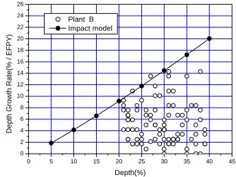
The wear depths of plant A are measured in the range of 14% to 40% of the tube thickness after 1EFPY has elapsed. The wear depths of identical tubes measured in the previous EFPY are measured again at 2 EFPY. Hence the growth of wear depths during 1 EFPY can be found. Similarly, the wear depths of plant B are measured at 4 EFPY and the wear depths of identical tubes measured in the previous 4 EFPY are measured at 5 EFPY. The measured wear depths are compared. The calculated growth depths between 1 EFPY and 2 EFPY of Plant A are compared with those measured in Fig. 3. The wear depths of Plant B are calculated using two methods. Namely, the growth of depths at 5 EFPY is found without including the past impacted number. The comparison of this result and that of measured depth is shown in Fig. 4.
Fig. 5 Predicted & measured wear depth. Fig. 6 Predicted & measured wear volume from 4 EFPY to 5 EFPY
The other method of finding the growth of depth is to include the effect of a past impact number, 4 EFPY. The results obtained using the second method are compared with those of the measured value in Fig. 5. The measured wear depths of plant A and B are a total of 163, and mean values for each wear depth are found. In the case of the rectangle type, wear volume per unit length during 1EFPY is found. The wear volumes are also calculated. Indirectly calculated wear volumes from average measured depths are compared with those found using the impact model in Fig. 6.
0 5 10 15 20 25 30 35 40 45 0
2 4 6 8 10 12 14 16 18 20 22 24 26
D
e
p
th
Gro
w
th
R
a
te
(%
/ EFP
Y
)
Depth(%) Plant A
Impact model
0 5 10 15 20 25 30 35 40 45 0
2 4 6 8 10 12 14 16 18 20 22 24 26
De
pth Gro
w
th
Rate(% /
EFPY
)
Depth(%) Plant B
Impact model
0 5 10 15 20 25 30 35 40 45 0
2 4 6 8 10 12 14 16
De
pt
h G
rowt
h
Rat
e
(% /
E
F
P
Y
)
Depth(%) Plant B
Impact model (Past cycle effect included)
15 20 25 30 35 40
1E-4 1E-3 0.01
Vo
lu
m
e
/
U
n
it
Cra
ck
Le
ng
th (in
^3/in
)
DISCUSSION OF RESULTS
The important assumption employed in the present calculation is that (3C/2)i is a constant during the short period from the time of measured depth. The near-distant future defines a number of impacts for 1 EFPY. If the difference between the time-predicted wear depth and the time-measured depth is not great compared with the lifetime of the plant, the wear depths can be predicted using the present method. The majority of the measured wear depths are enveloped by the predicted wear depth as shown in Figs.3 and 4.. The results shown in Figs. 3 and 4 are associated with those at 1 EFPY elapsed from the time of measured depth of tubes with natural frequencies. It is expected that the predicted wear depths are enveloped measured wear depths since the maximum impact velocity among the tube location in the S/G is used in the calculation. If the past impact number at the time of measured depths (4 EFPY in the present case) is included, the comparison of the predicted and measured depths is shown in Fig. 5. The predicted wear depths are much smaller than those of measured depths. Hence when the wear depths are predicted using the measured or postulated wear depths, it is suggested that the initial impact number, N1 from the time of measured depth is considered
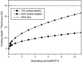
to be 1 EFPY including the natural frequency. It should be investigated further regarding the results shown in Fig 6. The reason for discrepancy between the predicted and measured value is not known at the present time. Namely if the number of impacts,N is increased, the variation of λ is decreased and this is expected since the peak contact stress is decreased with λ value in the progress of wear as shown in Eq. (18). The comparison of predicted wear volume with those obtained using averaged values of measured depths is shown in Fig. 5. The predicted wear volume envelopes those of measured and it is expected since the maximum impact velocity of the tube is used in the calculation. It is noted that the results shown in Fig. 6 are wear volume of the rectangle wear type, which result is shown in Fig. 7.
0 2 4 6 8 10
0 10 20 30 40
Fre
tting dep
th
/
T
h
ick
ness
(%)
Operating period(EFPY) 5% (initial depth)
10% (initial depth) 40% line
Fig. 7 Wear depth growth according to the operating period (updated are used)
CONCLUSION
Through these study, the following conclusions are derived: The predicted wear depth in the near--distant future using the material constant in the impact model
c
, obtained inversely from measured or postulated wear status, such as wear depth and impact number, envelopes the majority of the measured depths. This is expected since the maximum impact tube velocity in the S/G is used. The comparison of the predicted wear volume with the measured volume in the rectangle-wear type can provide similar conclusions to that of wear depths. Secondary, the method employed in the present paper may be used for an approximate estimation of wear depth in the near-distant future from known present wear status.REFERENCS
1. Waterhouse R. B., Fretting Wear, ASME Handbook, vol.18, Friction, Lubrication and Wear Technology, 1995. 2. Engel P. A., "Impact Wear of Materials", Tribology Series 2, Elsevier Scientific Publishing Co., 1978. 3. Engel P. A., Friction, "Lubrication and Wear Technology", ASME Handbook vol. 18, p.263, 1995. 4. Timoshenko S. and Goodier J. N., Theory of Elasticity, McGrawhill Book. Co., 1951.
5. Connors Jr. H. J., "Fluid Elastic Vibration of Heat Exchanger Tube Analysis", Trans. of ASME, '77-DET-'90, 1977.