NUMERICAL SIMULATION OF CONCRETE AND REINFORCED
CONCRETE UNDER HIGH RATE LOADING
Akanshu Sharma1, J. Ožbolt2, G.R. Reddy1, J. Hofmann2, K.K. Vaze1
1Reactor Safety Division, Bhabha Atomic Research Centre, Mumbai, INDIA-400085
2Institute for Construction Materials, University of Stuttgart, Germany-50689
E-mail of corresponding author: akanshu@barc.gov.in
ABSTRACT
Behavior of concrete/reinforced concrete structures is strongly influenced by the loading rate. The RC structural members subjected to impact loads behave quite differently as compared to the same subjected to quasi-static loading. The difference is attributed to the strain-rate influence on strength, stiffness, and ductility as well as to the activation of inertia forces. These influences are clearly demonstrated in experiments. Also, for concrete structures, which exhibit damage and fracture phenomena, the failure mode and cracking pattern depend significantly on loading rate. In general, there is a tendency that with the increase of loading rate the failure mode changes from mode-I to mixed mode. Furthermore, theoretical and experimental investigations indicate that after the crack reaches critical speed of propagation there is crack branching. In order to assess the performance of existing structures against impact loads that may be generated mainly due to man-made accidental conditions, it is important to have models that can realistically predict the impact behavior of concrete structures. The present paper focuses on 3D finite element study of plain and reinforced concrete structural specimens and elements such as compact tension specimen, beams and slabs under impact. The analysis is performed using the rate sensitive microplane model as constitutive law for concrete, while the strain-rate influence is captured by the activation energy theory. Inertia forces are implicitly accounted for through dynamic finite element analysis. The model has been implemented in 3D FE software MASA, developed at Institute of Construction Materials (IWB) University of Stuttgart. The numerical results are compared with experimental counterparts and it has been shown that the numerical analysis using the procedure followed in this work can very well simulate the impact behavior of reinforced concrete structural elements. Various aspects of high rate loading and its effect on different types of specimens are discussed in the paper. All the analytical observations are found to be in tune with the experimental observations as well.
INTRODUCTION
Reinforced concrete (RC) structures housing nuclear facilities must qualify against much stringent requirements of operating and accidental loads than conventional structures. Certain man-made hazards such as explosions, aircraft impacts etc are associated with high energy release in a relatively short period of time leading to the phenomena known as high rate loading or impact loading. Due to recent man made events, such impact loads are generally recommended to be used as a design criterion for important safety related structures. It is known that the behavior of concrete/reinforced concrete structures is strongly influenced by the loading rate. The RC structural members subjected to impact loads behave quite differently as compared to the same subjected to quasi-static loading due to the strain-rate influence on strength, stiffness, and ductility as well as to the activation of inertia forces. The response of structures depends on time dependent loading through three different effects: (1) through the viscous behavior of the bulk material between the cracks, (2) through the rate dependency of the growing microcracks and (3) through the influence of structural inertia forces, which can significantly change the state of stresses and strains of the material [1,2,3,4]. Depending on the type of material and the loading rate, the first, second or third effect may dominate. For quasi-brittle materials, such as concrete, which exhibit cracking and damage phenomena, the first effect is important for relatively low loading rates (creep-fracture interaction). However, the latter two effects dominate for higher loading rates (impact loading).
Further, for concrete structures, the failure mode and cracking pattern depend significantly on loading rate. In general, there is a tendency that with the increase of loading rate the failure mode changes from mode-I to mixed mode. In numerical modeling, the first two of the above mentioned effects can be accounted for by the constitutive law and the third effect should be automatically accounted for through dynamic analysis where the constitutive law interacts with structural inertia forces.
The model is based on the rate process theory [6] of bond ruptures. It is coupled with the M2-O microplane model for concrete [7], which has been shown to realistically simulate failure of concrete structures for complex three-dimensional stress–strain states.
MODELING OF CONCRETE UNDER HIGH LOADING RATE
The rate theory [6, 8]employed to explain the first two above-mentioned reasons for strain rate sensitivity
(micro-cracking and creep) assumes that crack initiation on an atomic scale is governed by the activation energy, i.e. in a non-stressed material there are the same number of bond-breaking and bond-healing steps in time. When an external force acts on the material there is a surplus of energy, which causes more bond-breaking than bond-healing steps. Since the number of bond-breaking steps is assumed to be constant in time that means that a longer loading time causes more ruptures than a shorter loading time. Expressed in terms of strength, it means that sustained loading and creep causes a reduction of strength whereas very short loading causes an apparent increase of strength. This means high loading rates increase the apparent strength of a material.
In literature, there are various two- and three-dimensional phenomenological models that are based on coupling of elastic, plastic, damage and viscose units in different combinations [9,10]. Depending on the model, the strain rate dependent material behavior is in the entire strain rate range described either better or worse. It has been
recently demonstrated that for low and medium strain rates up to 10 s-1, the total resistance is controlled by viscosity
and strain dependent crack growth [3,4,11]. However, at very high strain rates (impact) the inertial forces dominate and cause progressive increase of structural resistance and have dominant influence on failure mode and crack propagation [3, 4, 11,12].
Rate dependent microplane model for concrete
In the microplane model, material is characterized by the relation between stress and strain components on planes of various orientations. These planes may be imagined to represent damage planes or weak planes in the microstructure, such as those that exist at the contact between aggregate and the cement matrix. In contrast to phenomenological models for concrete, which are based on tensor invariants, in the microplane model the tensorial invariance restrictions need not be directly enforced. Superimposing in a suitable manner the responses from all the microplanes automatically satisfies them. The microplane model used in this work [7] is based on the so-called relaxed kinematic constraint concept. It is a modification of the M2 microplane model proposed by Bažant and Prat
[13]. Each microplane is defined by its unit normal vector components ni (see Fig. 1).
x y z microplane ε εV εM εD T ε K ε y x z n microplane microplane integration point FE integration point
Fig 1 Decomposition of the macroscopic strain vector into microplane strain components
Microplane strains are assumed to be the projections of macroscopic strain tensor εij (kinematic constraint).
On each microplane considered are normal and shear stress-strain components (σN, σTr, εN, εTr). To realistically
model the concrete, the normal microplane stress and strain components have to be decomposed into volumetric and
deviatoric parts (σN = σV+σD, εN = εV+εD). Based on the micro-macro work conjugancy of volumetric-deviatoric
split and using in advance defined microplane stress-strain constitutive laws, the macroscopic stress tensor is calculated as an integral over all possible, pre-defined, microplane orientations:
dS n n dS n n S rj j rj i Tr S ij j i D ij V
ij 2 2 ( )
where S denotes the surface of the unit radius sphere and δij denotes Kronecker delta. The integration is performed by numerical integration using 21 integration points (symmetric part of the sphere in Fig. 1). To account for large strains and large displacements, Green-Lagrange finite strain tensor is used. Furthermore, to account for the loading history of concrete, the co-rotational stress tensor is employed.
At the constitutive level the rate dependency consists of two parts: (1) the rate dependency related to the formation of the microcracks and (2) the rate dependency due to the viscosity of concrete between the microcracks. The influence of structural inertia forces on the rate effect is not a part of the constitutive law as this effect is automatically accounted for in dynamic analysis in which the constitutive law interacts with inertia forces. The rate dependent behavior of concrete is modeled based on the rate-process theory [14]. The influence of strain rate on the
rate insensitive microplane stress σ0m(εm), where m indicates microplane stress-strain components V, D and Tr, can
be written as [4,15]:
0 0
2 1
1
2
1
( )
( ) 1
ln
with:
2
m m m m ij ij
cr
c
c
c
c
s
γ
σ ε
=
σ
ε
⎢
⎡
+
⎜
⎛
⎞
⎟
⎤
⎥
γ
=
ε ε
=
⎝
⎠
⎣
⎦
(2)
where c0 and c2 are material constants, which have to be calibrated by fit of test data [16]. The calibration
of the constitutive law was carried out for moderate loading rates for which structural inertia forces have not much influence on the rate dependent response of concrete, i.e., only the rate of the crack growth controls the response. Thus, in the present model the entire rate dependency at the constitutive level is modeled by the rate theory [4,11].
Three-dimensional FE analyses
In this work, to perform the static and dynamic analysis within the framework of 3D finite element platform, rate sensitive microplane model discussed above is employed. Static analysis is performed using an implicit 3D FE code based on the incremental secant stiffness approach [17]. In the 3D transient dynamic FE
analysis the system of unknown displacements in each time step Δt is calculated by solving the following system of
equations (Voigt notation):
( ) +t ( ) - ( ) = 0t t
Mu Cu f (3)
where M = mass matrix, C = damping matrix, u= nodal accelerations, u = nodal velocities and f(t) = resulting
nodal forces. The resulting nodal forces are calculated as:
f(t) = fext(t) – fint(t) (4)
with fext(t) = external nodal forces and fint(t) = internal nodal forces. The system of equations (3) is solved using an
explicit direct integration scheme [17]. The external nodal forces are known nodal loads. The internal nodal forces are unknown and they are calculated by the integration of the stresses over the finite elements. In the FE code used in the numerical study the mass and damping matrices are assumed to be diagonal.
COMPACT TENSION SPECIMEN – FRACTURE OF CONCRETE AT HIGH LOADING RATE
It is known that when mode-I crack tends to propagate fast at the crack tip, inertial forces try to prevent this crack propagation and consequently single crack splits into two cracks (branching). The velocity of the crack
propagation also depends on loading rate. The maximal theoretical crack velocity is equal to Rayleigh wave speed vR
= CR (Gc/ρc)0.5 were the constant CR depends on Poisson’s ratio, Gc is the shear modulus and ρc is specific weight of
the material. For normal strength concrete Rayleigh wave speed is approximately equal to 2100 m/s. However, experimental, theoretical [18,19] and numerical investigations [11] indicate that a single mode-I type of crack cannot reach this theoretical speed of propagation. According to these investigations the maximal crack speed in concrete is
between 500 and 600 m/s [4]. Moreover, after crack speed reaches certain critical value there is crack branching
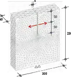
width-height-thickness = 200 x 250 x 50 mm and the notch length is 100 mm. The analysis is carried out for normal strength
concrete with the following properties: Young’s modulus Ec = 30000 N/mm2, Poisson’s ratio ν = 0.18, uni-axial
compressive strength fc = 40.0 N/mm2, tensile strength ft = 3.50 N/mm2, fracture energy G
F = 0.09 N/mm and concrete
mass density ρc = 2400 kg/m3. The spatial discretization is performed by four-node solid finite elements with constant
strain field. To assure objectivity of the analysis with respect to the size of the finite elements crack band method is used [20]. The load is applied by controlling horizontal displacement of the notch, applied 50 mm from the top of the specimen. To prevent local failure at the application of load, elements around the applied load are assumed to be linear elastic. The specimen is first analyzed assuming quasi-static loading condition. Subsequently, dynamic analysis
is carried out with the following loading rates Δ/dt = 1000 and 2500 mm/s.
Fig 2 Geometry of the compact tension specimen (in mm)
The calculated load displacement curves are shown in Fig. 3. It can be seen that with increase of loading rate peak load increases and for high loading rates it is much higher than the static resistance. This increase of resistance is due to structural inertia forces, which have in case of higher loading rates a major influence on structural resistance [19]. The peak load for static case was obtained as approximately 2.80 kN at a corresponding load point displacement of 0.04 mm. At 1000 mm/s load case, the inertia effects get dominant. Due to dominant inertia effects as well as rate sensitivity the peak load for this case was obtained as approximately 78 kN. The corresponding peak load displacement is obtained as 0.025 mm. In the load displacement curve, the oscillations are quite pronounced making the significance of inertia effects evident. The peak load for 2500 mm/s case was obtained as approximately 190 kN and the corresponding peak load displacement is obtained as 0.05 mm.
0 0,75 1,5 2,25 3
0 0,04 0,08 0,12 0,16 0,2 Displacement (mm)
Lo
a
d
(
k
N
)
0 20 40 60 80
0 0,1 0,2 0,3 0,4 0,5 Displacement (mm)
Lo
a
d
(
k
N
)
-50 0 50 100 150 200
0 0,2 0,4 0,6 0,8 1
Displacement (mm)
Lo
a
d
(
k
N
)
(a) Static (b) 1000 mm/s (c) 2500 mm/s
Fig 3 Load-displacement response obtained for different load cases
Fig. 4 shows the crack patterns in terms of maximal principal strains, for critical crack width wcr = 0.2 mm. It
can be seen that for quasi-static load there is a single mode-I crack, which propagates starting from the notch tip. However, for higher loading rates there is a branching of the crack and multiple cracking. For loading rate 1000 mm/s the crack starts as a single one from the notch tip and subsequently branches into two inclined cracks. For 2500 mm/s the crack branching starts already at the crack tip at onset of cracking and subsequently additional branching (multiple branching) is observed.
cracks. The direction of propagation of new cracks depends on the propagation of loading waves in damaged structure, which depends on material properties, current fracture configuration, geometry and loading rate. From theoretical investigations [18, 19] it is well known that with increase of the crack velocity the stress intensity factor at the crack tip decreases, i.e. if the crack speed approaches to Rayleigh wave speed the dynamic stress intensity factor approaches to zero. This blocks mode-I crack propagation and force the crack to branch in directions in which the stress intensity factor is higher.
(a) Static (b) 1000 mm/s (c) 2500 mm/s
Fig 4 Failure modes obtained for different load cases
NUMERICAL EVALUATION OF BEHAVIOR OF BEAMS AT HIGH LOADING RATE
The response of RC frame structures is mainly governed by the behaviour of the beams and columns. Saatci and Vecchio [21] performed experiments on simply supported rectangular RC beams under impact loads with two major objectives namely to understand the effect of shear mechanisms in the overall impact behavior of beams and to supply the literature with detailed impact test data. They tested beams having equal amount of longitudinal (bending) reinforcement for all cases but different amounts of transverse (shear) reinforcement to study the effect of transverse reinforcement on impact behaviour of beams. In this work, numerical simulation of the experiments by Saatci and Vecchio [21] is performed. The test setup at the supports was devised to prevent uplift of the specimen without creating restraint moments at the supports during the vibrations induced by impact loads (Fig 5). Fig 6 shows the details of the beams tested.
Fig 5 Test setup for impact tests on beams [21] Fig 6 Details of beams [21]
.
In this numerical work two types of beams (two different amount of stirrups) were analyzed, namely MS0, MS2, SS0a, and SS2a (Fig 6). Beams MS0 and MS2 were analyzed under static loading without giving any consideration to rate or inertia effects. The beams were loaded by controlling displacement at the mid-span of the beam. Beams SS0a and SS2a were analyzed under dynamic loads that were simulated by applying mid-point displacements at high rates corresponding to the displacement time plots as observed from the experiments [21]. The displacement at the mid span of the beam in experiments was observed to be increasing at a rate of around 750 mm/s for beam SS0a and 1000 mm/s for SS2a. The same loading rates were used to perform the analysis. Once, in the analysis, the experimentally measured peak displacement was reached the displacement condition was released and for the rest of the loading history the beam was free oscillating. Note that in this way the contribution of the mass of the hammer to the oscillation of the beam was neglected. FE analysis was performed using direct integration method of explicit type. To
get the analysis stable the time step Δt was set to 1x10⁻⁶s. The meshing for all the beam models was done with eight
Fig 7 shows the failure modes of the beams under static loads which clearly displays the formation of a principal diagonal shear crack in case of beams MS0, displaying a shear-critical mode, whereas MS2 exhibited a ductile flexural response. The maximum static reaction measured in tests was 98 kN, and 193 kN for MS0 and MS2 respectively. The same as observed in numerical analysis was 112, and 182 kN for MS0 and MS2 respectively. Thus, the analytical results are in tandem with the experimental results for all the three cases, both from the point of view of static reactions as well as failure patterns.
(a) MS0 (b) MS2
Fig 7 Failure modes obtained from static analysis of the beams
Fig 8 shows failure mode observed in the test for beam SS0a under dynamic impact load. Severe diagonal cracks were developed, originating at the impact point and propagating downward with an angle of approximately 45 degrees, forming shear-plugs. The flexural cracks were short and narrow and also certain vertical cracks were observed originating from the top of the specimen due to negative bending moments. Failure involved shear failure at supports in addition to the formation of shear plugs. This specimen did not have sufficient strength to transmit the shear forces to the supports. Consequently, the shear forces beyond the shear-plug caused extensive damage between the shear-plug and the supports, ultimately failing the beam in this region without exhibiting significant flexural deformations. The peak support reaction due to impact was recorded to be 305kN in the experiment.
Fig 8 Failure mode for SS0a as observed in test Fig 9 Analytical crack pattern for beam SS0a
The crack pattern due to dynamic loads as observed in the numerical analysis is shown in Fig 9. The peak support reaction from numerical analysis was found to be 346 kN. From Fig 8 and Fig 9 it can be clearly said that the analytical model and procedure followed in this case could replicate the test results numerically to a large extent. The support reactions, as well as the failure modes along with gradual crack formation and propagation obtained from the analysis match very closely with the experimental observations.
Beam SS2a had sufficient static shear strength. Fig 10 shows the failure mode observed in the test for beam SS2a under dynamic impact load. In this case, many distributed cracks were observed and shear-plugs developed faster than did the support shear cracks. Due to sufficient shear strength, the beam did not fail in the region between mid span and supports as in earlier case. Vertical flexural cracks at the mid-span were more visible and wider and again vertical cracks were observed originating from the top of the specimen due to negative bending moments. The peak support reaction due to impact was recorded to be around 327 kN in the experiment. This suggests that the dynamic reaction is independent of the shear reinforcement, but the crack patterns are dependent on the same.
The crack pattern due to dynamic loads as observed in the numerical analysis for beam SS2a is shown in Fig 11. In the beginning, a few vertical cracks originate from the bottom near mid span and from top of the beam near supports and at 50% of peak displacement, shear cracks appear propagating at 45 degrees angle. On further loading, more shear cracks start to appear but in a more distributed fashion, unlike the earlier case where the shear cracks conglomerate together and cause large spalling of side cover of the beam. Thus, it can be said that the numerically obtained failure mode is very similar to the experimentally observed one. The peak support reaction from numerical analysis was found to be around 314 kN, which is again close to experimental value and further suggests that the dynamic reaction, unlike the failure pattern is independent on the amount of shear reinforcement.
Fig 10 Failure mode for SS2a as observed in test Fig 11 Analytical crack pattern for beam SS2a
NUMERICAL EVALUATION OF BEHAVIOR OF SLABS AT HIGH LOADING RATE
dynamic loads. Though, the resistance of such panels under dynamic loads in general is much higher than under static loads, the sudden failure under punching shear can be dangerous. In this section, the results of the effect of various loading rates on load-deflection behavior and failure mode of a reinforced concrete slab are reported. For analysis, a slab having plan dimensions as 4m x 4m and 150 mm thick was considered for analysis. Boundary conditions were selected similar to as in case of continuous slabs and the reinforcement was considered as 10 mm dia bars @ 200 mm c/c top and bottom both ways. At the centre of the top face of the slab, a steel plate of size 500mm x 500mm and 25 mm thick was considered on which load was applied. The load was applied in displacement control mode with the centre point of the bottom face of the slab as the monitoring point. The load was applied only at two different loading rates viz (i) Statically (ii) displacement increasing at the rate of 1000 mm/s. To take advantage of symmetry in dimensions and loading, only 1/4th model of the slab was modelled.
Fig 12 shows the load-deflection curve for the slab obtained for static load case. The peak load resisted by the slab in this case was obtained as 121 kN corresponding to a center point deflection of around 25 mm. Fig 14 shows the principal tensile strains (cracks) observed for this load case. Clear yield lines propagating from the load point towards the corners of the edges suggesting flexural failure can be observed. However, as the load is increased, shear component starts to dominate and the final failure occurs due to a flexure-shear combination.
0 20 40 60 80 100 120 140
0 15 30 45 60 M id Span Deflection (mm)
Lo
a
d
(
k
N
)
X
750.
900.
Fig 12 Load-deflection curve for slab under static load case
Fig 13 Crack pattern for static load case
Fig 14 shows the load-deflection curve obtained for the slab when it is loaded at the rate of 1000 mm/s. The peak load resisted by the slab in this case was obtained as around 1120 kN which is much higher than that obtained due to static loading case. However, the displacement corresponding to peak load was only 3 mm as against 25 mm for the case of static loading. Such a significant change in the load displacement behaviour suggests a clear transformation from the flexure failure mode to punching shear failure mode. This was further confirmed by the crack patterns observed (Fig 15), which clearly displayed the punching shear failure of the slab.
0 200 400 600 800 1000 1200
0 5 10 15 20 25 M id Span De fle ction (mm)
L
oad
(
k
N
)
Fig 14 Load-deflection curve for 1000 mm/s loading rate Fig 15 Crack patterns for 1000 mm/s load case
CONCLUSION
increase of loading rate, i.e. multiple crack branching is observed. The predicted rate dependent fracture is in good agreement with experimental observations and theoretical predictions. The highest crack velocity is approximately 500 m/s and it is measured at the onset of crack branching. For static loads, the failure mode of RC beams depends significantly on the amount of shear reinforcement. However, for higher loading rates regardless of their projected static behavior, all specimens developed severe diagonal cracks, originating at the impact point and propagating downward with an angle of approximately 45 degrees, forming shear-plugs. The static reaction depends largely on the amount of shear reinforcement and on the fact whether the beams are shear or flexural critical. However, the dynamic reactions were found to be independent of the amount of shear reinforcement. The RC slabs change the failure mode from flexural to punching shear under high loading rates. The numerical model is able to simulate the failure modes and reactions in close agreement with the experimental results thereby confirming the utility of the modelling technique to simulate RC structures under impact loads.
REFERENCES
[1] Bischoff, P. and Perry, S. Compressive behavior of concrete at high strain rates, Mat. And Struct., 1991, 24, 425-450.
[2] Larcher, M. Development of Discrete Cracks in Concrete Loaded by Shock Waves, Int. J. Impact Engg, 2009, 36, 700-710.
[3] Ožbolt, J. and Reinhardt, H. W. Rate dependent fracture of notched plain concrete beams. Proc. 7th int conf CONCREEP-7, Eds. Cabot, Gerard & Acker, 2005, 57-62.
[4] Ožbolt, J., Sharma, A., and Reinhardt, H. W., 2011. Dynamic fracture of concrete – compact tension specimen, International Journal of Solids and Structures, 48, 1534-1543.
[5] Reinhardt, H. W. Concrete under impact loading, Tensile strength and bond. Heron, 1982, 27, No.3 [6] Weerheijm, J. Concrete under impact tensile loading and lateral compression. Dissertation, TU Delft, 1992 [7] Ožbolt, J., Li, Y.-J. and Kožar, I. Microplane model for concrete with relaxed kinematic constraint. Int J
Solids and Struct, 2001, 38, 2683-2711
[8] Mihashi, H., Wittmann, F.H. Stochastic approach to study the influence of rate of loading on strength of concrete. HERON, 1980 25(3)
[9] Holmquist, T. Johnson, G. And Cook, W. A computational constitutive model for concrete subjected to
large strain, high strain rates and high pressures, 14th Int Sym on Ballistics, Quebec, 1993, 591-600
[10] Rabczuk, T. and Belytschko, T. Cracking particles: a simplified meshfree method for arbitrary evolving cracks, Int J. Numerical Methods in Engg, 2004, 61, 2316-2343
[11] Travaš, V, Ožbolt, J., Kožar, I. Failure of plain concrete beam at impact load: 3D finite element analysis. Int. J. Fracture, 2009, 160: 31-41
[12] Reinhardt, H. W., Ožbolt, J. and Travaš, V. Response of concrete members to impact loading, Dynamic fracture of concrete – compact tension specimen, FraMCoS-7, Jeju, Korea, 2010, 1701-1714.
[13] Bažant, Z. P. and Prat, P. C. Microplane model for brittle-plastic material - parts I and II. J. Engg. Mech. (ASCE), 1988, 114, 1672-1702
[14] Krausz, A. S. and Krausz, K. Fracture kinetics of crack growth. Kluwer, Dordrecht, The Netherlands, 1988. [15] Bažant, Z. P., Adley, M. D., Carol, I., Jirasek, M., Akers, S. A., Rohani, B., Cargile, J. D. and Caner, F. C. Large-Strain Generalization of Microplane Model for Concrete and Application. J. Engg. Mech. (ASCE), 2000a, 126(9), 971-980.
[16] Dilger, W. H., Koch, R. and Kowalczyk, R. Ductility of plain and confined concrete under different strain rates. ACI Special publication, Detroit, 1978
[17] Belytschko T., Liu W. K. and Moran, M. Nonlinear Finite Elements for Continua and Structures. John Wiley & Sons Ltd, 2001
[18] Freund, L. B. Crack Propagation in an Elastic Solid Subjected to General Loading-I. Constant Rate of Extension. J. Mech. Phys. Solids, 1972a, 20, 129-140.
[19] Freund, L. B. Crack Propagation in an Elastic Solid Subjected to General Loading-II. Non-uniform Rate of Extension. J. Mech. Phys. Solids, 1972b, 20, 141-152.
[20] Bažant, Z. P. and Oh, B. H. Crack band theory for fracture of concrete. RILEM, 1983, 93(16), 155-177. [21] Saatci, S. and Vecchio, J. V. Effect of Shear Mechanisms on Impact Behavior of Reinforced Concrete