Automatic Headlamp Illumination Control
System
Prof. Pratik Ashok Patil, Shubham Sunil Badave, Shubham Sunil Ingwale
Assistant Professor, Department of Mechanical Engineering, AMGOI, Vathar tarf Vadgaon, Kolhapur,
Maharashtra, India
UG Student, Department of Mechanical Engineering, AMGOI, Vathar tarf Vadgaon, Kolhapur, Maharashtra, India
UG Student, Department of Mechanical Engineering, AMGOI, Vathar tarf Vadgaon, Kolhapur, Maharashtra, India
ABSTRACT: Night time driving with conventional headlamps is particularly unsafe as the highest fatal traffic accidents rate occurs on curve roads at night time. Historical data shows that, only 25% of driving is done at night time but, even though 55% of driving accidents occur during this period. The existing conventional light system does not provide illumination in right directions on curvature road as headlamp position remains fixed for any steering action. Due to insufficient illumination, conventional headlamp doesn’t cover the full road during taking turn on curvature, so it becomes the major threat of accidents. In order to enhance night time driving safety, this paper work aims to project the headlamp lights at required position of road in accordance with steering action. A proposed system for automatic headlamp position control system consist of potentiometer as sensing unit, MCS 51 microcontroller as control unit and three headlamps as actuation unit.
KEYWORDS: Accidents, Automatic, Headlamp, Position Control
I. INTRODUCTION
Although, in the conventional headlamp control system, driver has control of the headlight which can be switched from high beam (bright) to low beam (dim), this is insufficient while driving on curved roads. Over 50% of all road traffic accidents occur at night time. The focus is to improve visibility for the driver, thereby increasing driving safety. Various studies on swivel beam headlamp have shown up to 300% increase in illumination of the driver’s gaze point as the vehicle turns on a corner. The additional corner illumination results in 58% increases in the driver’s ability to recognize an obstacle.
The requirement of headlight is a necessity during night travel. The same headlight which assists the driver for better vision during night travel is also responsible for many accidents. The driver has the control of the headlight which can be switched from high beam (bright) to low beam (dim). Presently, studied changes are unfolding in automotive lighting technology. Automobile manufacturers - together with suppliers and representatives - currently aspire to develop the headlights of tomorrow. Freeform headlamp is one of the popular design which offers great flexibility and compactness.
steering angle sensor. Some systems proposed automatic optical-axis adjusting device for automatically adjusting direction of optical axes of front lights with respect to steering angle of steering wheel.
II. PROBLEM DEFINITION AND PROBLEM STATEMENT
The traditional vehicle headlamp light system does not provide illumination in right direction and at precise angle on curvature road, due to these constraints, a need of alternative solution and advancement in the traditional technology arises which will focus light in all the required sides of the vehicle during taking a turn.
The general problem is to design a system which can analyze road conditions to identify situation in which adaptive road illumination system could enhance visibility, and thereby substantially improve safety and/or comfort for road users. The main goal of this proposed project is to discuss ways in which the present, static vehicle illumination systems could be improved by making them dynamic more adaptable to the ever changing road conditions, mainly curves
III. RELATED WORK
The existing conventional light system does not provide illumination in the right direction and at the precise angle. The objective of this paper is to design and build an Adaptive Front Light Control System Prototype. The literature concludes that, the headlamp swings in horizontal direction by sensing steering angle and vertical by sensing distance between subject vehicle and next vehicle [1]. According researcher, in most cases, the late recognition of objects in the traffic zone plays a key role. In order to provide enhanced nighttime safety measures, the researcher aims to design and build a prototype of steerable headlights by adapting a conventional static headlamp [2].
Another referenced literature presents the automatic headlight switching system switches the high beam lamp to low beam as soon as it senses a vehicle approaching from the opposite direction and switches it back to high beam when the cars pass each other. The design minimizes accidents occurring at night time as a result, the glare helps to controls headlamp automatically for the automobile [3]. The research even aims to improve visibility for driver and to achieve a significant increase in safety and driving safety. This flexible front light of automobiles is to illuminate road ahead in the night at corner. AFS (adaptive front-lighting system) is used to detect information about corner in advance with help of sensor which detects the information sends relative information to motor. Accordingly motor adjust headlamps to get the lighting beam which is suitable for the corner [4]. A smart solution to automated headlamp presents the hardware of movable headlight system for vehicles. The headlamp orientation control system rotates the right and left headlights independently and keeps the beam parallel to the curved roads to provide better visibility to driver at night time. In this system use of rack and pinion arrangement gives to the optical axes on which headlight are mounted so tie rod arms are moved with steering arm that give predefined motion to the wheel as well as headlights [5].
IV.METHODOLOGY
The purpose here is to modify the conventional headlight by providing three light sources on each side of headlamp. The unfocused road is made visible by providing assisting main headlight by another light source in each headlamp. In order to manage system costs and complexity, a simple framework was laid out for the developed Automatic Headlamp System. This concept consists of three important components: input sensors to monitor the position of steering, a microcontroller as brain of the system, and two light sources for illuminating the headlights.
The proposed system flow is illustrated in Figure 1 which shows that, the system first collects inputs, processes them and then accordingly operates actuators. In this design, there is no requirement for a feedback loop between the headlight positioning and the microcontroller.
Figure 1: Block Diagram of the system
A. SENSOR BLOCK
The position of the headlights is dependent on the direction of the vehicle so the input to the headlight system is attached to the vehicle’s steering shaft. A simple potentiometer is attached to monitor steering system and feed related signal to the microcontroller. As the steering shaft rotates (taking corners), it will turn the potentiometer and therefore vary the voltage input. The voltage input that varies from 0-5 volts is converted into digital input via the A/D channel of the microcontroller. For example, if the headlight is set at the center with an initial voltage of 2.5V, if the voltage increases as the potentiometer turns, the microcontroller reads this voltage increment and will adjust headlamp brightness as required.
Figure 2: Rotary Potentiometer (a sensing unit)
The position of headlight should be adjusted upon direction of the vehicle. Direction of the vehicle is controlled by steering system which uses either rack and pinion gear assembly or hydraulic actuation. As the steering shaft is rotated, pinion rotates which makes the rack to slide and hence the wheels are turned. The position of headlight should be
Sensor
Potentiomete r
System
Headlamp Steering
Actuator
Headlamps
Control unit
adjusted upon direction of vehicle for better visualization of driver. In the traditional headlight system intensity of headlamp lights remain same and the illumination of light stays parallel to the direction of vehicle which may not focus light on required side of the road.
Sensing unit used in this work is consisting potentiometer. The working of potentiometer shown in figure 2 is as described below;
A constant input voltage supply Vin is applied across the terminal 1 & 3.
A variable output voltage Vout is taken across the terminal 2 & 3. Terminal 2 is sliding contact & is attached to the steering shaft. The position of sliding contact depends upon the angular position of steering shaft.
As the contact 2 slides, the resistance between terminals 2 & 3 changes, which is the measure angular position of steering and calculated by
= (∴V∝R) (R13 is constant)
V V
Sensing unit monitors the position of steering shaft and sends the signal to control unit.
B. MICROCONTROLLER
A Programmable Intelligent Computer (PIC) microchip is to be used to control the brightness of headlights. The PIC is an 8 bit microcontroller. The PIC must have availability, low price, reliability.
Control unit is use d in this automated headlamp system is intel-MCS-51. MCS-51 is a microcontroller with 40 pins. It has 4 input/output ports each of 8 pins. It has signal of +5V (DC). Potentiometer can be connected to the port 1(pin 4-pin 12). Microcontroller is programmed by using assembly language.
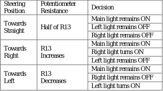
When input (steering shaft rotation) is given to the control unit (microcontroller MCS 51) via potentiometer, it will brighten the headlamps as per the program stored in the memory. The working of control unit based on different positions of steering is expressed in below table 1.
Steering Position
Potentiometer
Resistance Decision
Towards
Straight Half of R13
Main light remains ON Left light remains OFF Right light remains OFF
Towards Right
R13 Increases
Main light remains ON Right light turns ON Left light remains OFF
Towards Left
R13 Decreases
Main light remains ON Right light remains OFF Left light turns ON
Table 1: Control unit decisions based on steering positions
From table 1, when vehicle is moving straight then in each headlamp, only main light remains ON while assistant lights are kept OFF. The resistance value read by potentiometer at this particular steering position is half of total resistance R13.
While taking left turn, main light should remain ON but, for better visibility of driver left side area of road should be brightened which is done by left side assistant light source provided at left side headlamp. As the vehicle is turning towards left, the resistance R13 decreases which brightens the left side headlamp.
C. ACTUATOR BLOCK
The actuator of this system is headlamp. In this system there are three lights which are decided to be turn ON or OFF according to the decision taken by microcontroller. According to the decision of control unit the right side bulb or left side bulb will be turned ON or OFF. Actuator receives signal from control unit and it depends upon the steering position supposed to focus the light in the required side of the road.
Figure 3: Headlamps arrangement in the prototype
As shown in figure 3, each headlamp has two light sources. Right side light has main light and assistant right bulb while left side lamp has main light and assistant left bulb. When a headlight is turned ON main light remains ON but the ON/OFF and brightness of left and right assistant bulb is done on the basis of steering position and it is as discussed in the control unit part.
V. CONCLUSIONANDFUTUREWORK
From the review of literatures, one can conclude that, the better road illumination is important to reduce road accidents and hence, to increase night time driving safety. The prototype presented this paper can modify the traditional headlamp system and enhance the illumination of the headlamps on curvature roads. Adapting this kind of automatic headlamp illumination system, driver’s safety can be increased without compromising driving comfort.
ACKNOWLEDGMENT
This thesis includes detailed information about automating headlamp illumination control while driving at night times. The ideas, development and writing up of this paper are the principal responsibility of all the authors and it is done under the supervision of Prof. Pratik Patil.
REFERENCES
1.Ganesh Dhamdhere, Sandhya Chourasia, Sumit Sasatte, Lect. P. K. Warkey, “ Adaptive Front Light Control System for Every Vehicle”,
International Journal of Advanced Research in Electronics and Communication Engineering (IJAREE), 2015, Vol-4(4), pp-1091-1094.
2.Rajesh.G, “Automatic Headlamp Steering System”, International Journal of Engineering Development and Research (IJEDR), 2014, Vol-2, (2),
pp-2053-2056.
3.O. Akinsanmi, A. D. Ganjang, H. U. Ezea, “Design and Development of an Automatic Automobile Headlight Switching System”, International
Journal of Engineering and Applied Sciences (IJEAS), 2015, Vol-2 (8), pp-107-112.
4.Priyanka Dubal, Mr. Nanaware J.D, “Design of Adaptive Headlights for Automobiles”, International Journal on Recent and Innovation Trends in
Computing and Communication (IJRITCC), 2015, Vol-3(3), pp-1599-1603.
5.Manisha V Makwana, Akshay Shah, Shankar Rahul, Ajay M Patel, “Design and Manufacture of Movable Headlight System in Automobile”,
International Journal of Innovative and Emerging Research in Engineering, 2014, Vol-1(2), pp-12-16
6.Shinde Ganesh R., Jadhav Tushar D., Varade Shubham A., Korde Goraksha K, Belkar S. B., “Adaptive Headlamp System” International Journal
of Informative & Futuristic Research (IJIFR), 2015, Vol-2(7), pp-2290-2295
7.Prajakta Vikas Adhav, Prof. S. A. Shaikh, “Adaptive Front Lighting System Using CCD”, IOSR Journal of Electronics and Communication
Engineering (IOSR-JECE), 2014, Vol-9(5), pp-20-25
8.Muralikrishnan. R, “Automatic Headlight Dimmer A Prototype For Vehicles”, International Journal of Research in Engineering and Technology,
2014, Vol-3(2), pp-85-90
9.Meftah Hrairi and Anwar B. Abu Bakar, “Development of an Adaptive Headlamp Systems”, International Conference on Computer and
Communication Engineering (ICCCE), 2010.
BIOGRAPHY
Prof. Pratik Ashok Patil M. Tech (Mechatronics) Assistant Professor AMGOI, Vathar
Mr. Shubham Sunil Badave BE (Mechanical)
Student AMGOI, Vathar
Mr. Shubham Sunil Ingwale BE (Mechanical)