Experimental Performance of Pneumatically
Driven Mechanical Robotic Arm for Pick and
Place Operation
V.Karthi
1, J.Alageswaran
2, P.Boopathi
3, M.Mohamed haaris
4, Asst.prof. J.Saravanan
5Department of Mechanical Engineering, Angel College of Engineering and Technology, Tiruppur, Tamilnadu, India
ABSTRACT: This study was conducted to create a prototype of pneumatically driven mechanical robotic arm (made up of steel rods) for pick and place operation using a steel plate gripper. The system incorporates pneumatics components to drive an arm, pneumatic pressure cylinders through solenoid valve supply lines. The arm consists of a pneumatic hand and pneumatic wrist which can grasp various
Small, light-weight objects without force sensors or feedback control. Therefore, this study aims to control the wrist motions to expand the hand motion’s space. The hand imitates the human hand shape and can grasp Objects that have different shapes and mechanical characteristics. The wrist has redundant degrees of freedom which is useful when the robot moves to avoid obstacles. However, the drive mechanism of the wrist has non-linearity from a mechanical viewpoint. Also, the pneumatic actuators used as the drive source have hysteresis characteristics. These features make the wrist motions difficult to control as the wrist is used in material handling systems, its motions need to be freely controlled. To that end, in this research, experimental model of the drive system of the pneumatic robot wrist has been constructed.
KEYWORDS: Robot Arm, Pick and Place Operations, Material Handling, Pneumatic Actuator
I. INTRODUCTION
A robotic arm is a robot manipulator, usually programmable, with similar functions to a human arm. The links of such a manipulator are connected by joints allowing either rotational motion (such as in an articulated robot) or translational (linear) displacement. The links of the manipulator can be considered to form a kinematic chain. The business end of the kinematic chain of the manipulator is called the end effectors and it is analogous to the human hand. The end effectors can be designed to perform any desired task such as welding, gripping, spinning etc., depending on the application. For example robot arms in automotive assembly lines perform a variety of tasks such as welding and parts rotation and placement during assembly. The robot's muscles come in the form of actuators that convert hydraulic, electrical or pneumatic energy into power for each joint. Next there is an electronic nervous system of wires and sensors that carries commands to the muscles of the robotic arm and then back to an external computer.
The main difference between the arm of the robot and that of a human is found at the arm's extremity. Rather than having a flexible, multi-fingered hand, typical robot arms end in special-purpose devices called end-effectors, which are installed directly into the wrist. To reduce the number of calculations, needed to determine the robot's exact position, the base is generally kept stationary.
II. PNEUMATIC DEVICES
without electric-shock hazard. A relatively small compressor suffices to fill a storage tank for intermittent use, and no return lines are needed. Other characteristics of a compressed-air system are important in meeting special service requirements. It is relatively easy to connect one device (such as a valve or a cylinder and piston) to another by pipe, tubing, or flexible hose. Many actions can be driven by a simple manipulation of valves. The motion of an actuating piston in a cylinder can be changed quickly and in small steps with practically no shock. An air system can provide great flexibility in speed and motion control. Relief valves are easily arranged to protect a system and avoid damage. Control of operations is simple, efficient, and centralized. In general, air systems have relatively few moving parts, contributing to high reliability and low maintenance costs.
A. Major types of pneumatic devices
Air compressors and pneumatic tools constitute the principal classes of pneumatic devices. Other kinds of apparatus that make use of compressed air are paint-spray equipment, pneumatic tubes for conveying materials, and train brake systems. An air compressor is a power-driven machine for compressing air from some initial intake pressure (usually atmospheric) to a higher pressure. Compressors (as well as other fluid machines) can be classified into two main types, depending on the air or fluid action: (1) the positive-displacement type and (2) the velocity, or dynamic, type.
In the positive-displacement, or static-pressure, type, the characteristic action is a volumetric change or displacement action. Successive volumes of air are confined within a closed space, and the pressure is increased by reducing the volume of the space. In the simple hand tire pump, pressure is developed by moving a piston in a cylinder. The positive-displacement type may be subdivided into reciprocating (back-and-forth straight-line motion) and rotary (motion in a circular path) compressors. In a positive-displacement machine, neglecting leakage, the volume rate of flow (cubic feet per second) through the compressor is essentially constant over a wide range of discharge pressures.
The dynamic type of compressor may be subdivided into the centrifugal type (with flow through a rotating runner or rotor primarily in a radial direction), the axial-flow type (with flow through a runner primarily in a direction parallel to the axis of rotation), and the fluid-jet type.
Pneumatic tools can be separated into two broad categories on the basis of the driving method: rotor and reciprocating piston. Both kinds are known as air motors. A rotating type of compressor, operating in reverse, serves as one type of motor. Compressed air enters the housing, pushes on the vanes, and rotates a central shaft or spindle. A drill, grinding wheel, or other device is fastened to the spindle. A reciprocating-piston compressor, operating in reverse, also functions as a motor. Compressed air enters the cylinder, expands, and forces the piston to move. The return stroke may be actuated by compressed air on the other side of the piston or by spring action. A tool, such as a riveting hammer, may be connected to the reciprocating piston.
Pneumatic tools are normally supplied with compressed air at about 90 psig (pounds per square inch gauge). With compressed air as the power source, tools have been designed that are relatively lightweight, compact, portable, and easy to operate, and free from electrical shock and spark hazards. In underwater operations, compressed air prevents water from entering the air motor.
Pneumatic tools can also be divided into two groups according to the type of tools: portable tools and rock drills. Portable pneumatic tools include abrasive devices (e.g., grinders, buffers, and sanders), drills, reamers, tappers, stud setters, screwdrivers, nut setters, shears, wrenches, and impact tools. They are normally powered by a rotary-vane type of air motor. Operating speeds can be varied by throttling the air to the motor. Air motors do not become hot when overloaded; they will stand repeated stalling and rapid reversals without damage. Grinders feature air motors, which are typical for this class of device.
mechanism to control the airflow to the piston, thus allowing the operator to control the speed and force of the blows. In a compression riveter the compression or squeezing action, on the rivet is obtained from an air piston connected to a cam, wedge, or toggle. A yoke riveter has an air-operated clamp or vise that holds the work in place; the yoke absorbs the hammering action and thus reduces operator fatigue. Hoists operated by compressed air are employed in operations requiring accurate control of lifting or lowering speeds. In most cases, they are used outdoors and under conditions in which corrosive fumes, explosive gases, or inflammable fluids are present.
There are also various portable specialty tools, such as concrete vibrators, countersinking tools, spike drivers, paint mixers, air cranking motors, railway roadbed tampers, valve grinders, reciprocating filing machines, and shank grinders.
Rock drills are used for mining and rock excavation. An example of such a pneumatic tool is the hammer drill, or percussion hammer, which is composed of a piston and a drill made of high-carbon steel. The drill is held loosely in a chuck at the end of the cylinder and is struck by rapid blows from the freely moving piston. For downward-sloping holes, some means must be provided for removing drill cuttings, dust, and sludge. A hollow drill is usually used, and water or air is passed through it to remove the cuttings and cool the drill bit. Another kind of rock drill, called the drifter drill, is used for horizontal holes in mining operations and tunnel driving.
It is mounted on some type of rig or frame and is mechanically fed into the work. Stopper drills are used primarily on up-hole or overhead drilling because of the automatic-feed characteristics. The usual stopper is a hammer drill with a self-rotating drill bit and an automatic feed by means of an air piston. Large air-operated earth drills, mounted on motor trucks on trailers, are utilized for digging water wells and blast holes for quarry operations. A high-capacity compressor provides air not only to power the drill tool but also to raise the tools in the hole and to remove drill cuttings from the hole. Such machines are used to advantage in areas where surface water supplies are insufficient to provide the drilling fluid needed for standard rotary and cable-tool well-drilling machines.
Hand-operated pneumatic paving breakers usually use solid steel drills and are not equipped for automatic rotation. One type of tool is valve-actuated, another is valve less. Heavy machines of about 80 pounds (36 kg) are used to break concrete pavement, foundations, and boulders. Medium breakers, weighing about 50 to 70 pounds (23 to 32 kg), are employed when breaking light concrete floors, macadam, and frozen ground. Light tools, weighing less than 50 pounds, are used to break floors, paving, and masonry walls. Heavy and medium-weight breakers can be adapted for driving spikes.
Compressed air is a good vehicle for conveying a paint spray. In a spray gun, the paint (e.g., lacquer, enamel, or plastic coating) is atomized and mixed with compressed air. The principle of operation is similar to that of the jet compressor, with the compressed air serving as the motive fluid to draw the paint into the mixing area. Spray painting usually implies covering relatively large surfaces, such as a building. The term airbrush, by contrast, implies a device for developing a fine, small diameter spray of paint, protective coating, or liquid color. The airbrush can be a pencil-shaped atomizer used for a variety of much more detailed activities such as shading drawings and retouching photographs.
Certain recently developed vehicles are supported by a cushion of air. The most successful of these air-cushion vehicles (ACVs) is the British-made Hovercraft. It is used commercially as a passenger- and car-carrying
ferry; a number of them ply the English Channel.
Experimental “tracked skimmers” (air-cushion trains) are under development in a number of countries, but they are not yet used commercially to any great extent. In the planning of many city transit systems, consideration is being given to air-cushion vehicles capable of speeds up to 300 miles (480 km) per hour. Other specialized forms of air-cushion vehicles have been designed for use over rough terrain—such as that in Arctic regions—and for other uncommon applications.
Brakes on trains and most buses and large trucks are operated by air pressure. A piston rod from an air cylinder exerts force on the braking device. On railroad cars the air-brake system includes a compressor, pneumatic valves, regulators, piping, reservoir, and other accessories. There are levers, cylinders, and other rigging to apply forces to the brake shoe, which bear directly on the rim of the wheel. Various automatic-control safety arrangements assure a definite braking
action should some malfunction develop.
Pascal’s Principle: also called Pascal’sLaw, in fluid(gas or liquid) mechanics, statement that in a fluid at rest in a closed container a pressure change in one part is transmitted without loss to every portion of the fluid and to the walls of the container. Pressure is equal to the force divided by the area on which it acts. According to Pascal's principle, in a hydraulic system a pressure exerted on a piston produces an equal increase in pressure on another piston in the system. If the second piston has an area ten times that of the first, the force on the second piston is ten times greater, though the pressure is the same as that on the first piston. This effect is exemplified by the hydraulic press, based on Pascal's principle, which is utilized in such applications as hydraulic brakes. Pascal also discovered that the pressure at a point in a fluid at rest is the same in all directions; the pressure would be the same on all planes passing through a specific point. This fact is also known as Pascal's principle.
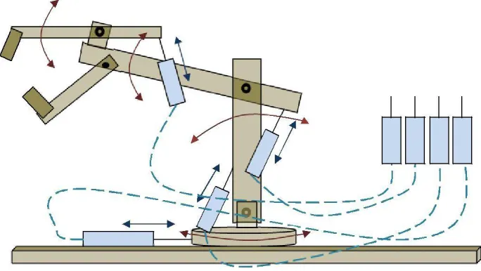
III. WORKING OF THE MODEL
The shown model of the robotic arm consists of a robotic arm designed so as to control the movements through pneumatic pressure cylinders connected to it. The supply of air pressure is given through an air supply unit consisting of four cylinders supplying the pressure individually to every cylinder connected to the joints.
The shown robotic arm works through the pneumatic pressure supplied to the actuators by the cylinders 1, 2, 3 & 4.
gripper and outward piston movement causes closing of the gripper.
(ii)The air pressure of the cylinder 2 causes the motion of the arm holding the end effectors up or down by the supply of the air pressure to the actuator through the supply lines. The inward motion of the piston of the actuator causes the lifting of the arm and outward piston movement causes downward motion of the arm.
(iii) The air pressure of the cylinder 3 causes the motion of the whole of the robotic arm up or down by the supply of the air pressure to the actuator through the supply lines. The inward motion of the piston of the actuator causes the downward motion of the body and outward piston movement causes lifting of the body.
(iv)
The air pressure of the cylinder 4 causes the revolute motion of the robotic arm by the supply of the pressure to the actuator through the supply lines. The inward motion of the piston of the actuator causes the clockwise motion of the arm body and outward piston movement causes anti-clockwise motion of the arm body.The end effectors are designed to hold objects by gripping them by pneumatic pressure and release them as and when required by operating the air pressure. This model works as a pick and place robot, capable of picking objects from one location and drop them at the desired location. The operating pressure is variable with maximum pressure up to 2 bars depending on the applied force.
IV. WORK VOLUME
The term "work volume" refers to the space within which the robot can operate. To be technically precise, the work volume is the spatial region within which the end of the robot's wrist can be manipulated. Robot manufacturers have adopted the policy of defining the work volume in terms of the wrist end, with no hand or tool attached.
Fig. 1. Pneumatically Driven Robotic Arm.
LEGEND
The work volume of a jointed arm robot will be somewhat irregular, the outer reaches generally resembling a partial sphere. Robot manufacturers usually show a diagram of the particular model's work volume in their marketing literature, providing a top view and side view with dimensions of the robot's motion envelope.
Fig. 2. List of Symbols used.
V. RESULT AND CONCLUSION
There are several benefits of using a robot with the following parameters:
The amount of force exerted by pneumatic cylinders decides the lifting and dropping of an object. The robot has a cylindrical work configuration with a maximum vertical reach of 52 cm and vertical stroke of 16 cm. The swivel angle is 260°. The calculated work volume is 19188.54 Cubic Cm.
REFERENCES
[1] Rongjie Kang, David T Branson, Tianjiang Zheng. Emanuele Guglielmino1 and Darwin G Caldwell1Design, modeling and control of a pneumatically actuated manipulator inspired by biological continuum structures,
[2] An anthropomorphic robot arm driven by artificial muscles using a variable structure control, Hamerlain, M. ; Lab. de Robotique et d''Intelligence Artificielle, Alger, Algeria, Intelligent Robots and Systems 95. 'Human Robot Interaction and Cooperative Robots', Proceedings. 1995 IEEE/RSJ International Conference on (Volume:1).
[3] Technical guide of the soft Arm, 1985.
[5] M. Hamerlain, B. Tondu, C. Mira & P. Lopez (1991). "Variable structure control for an actuator with artificial antagonistic muscle", Workshop on variable structure control of power conversion systems, EEEE, NEVADA,
[6] M. Hamerlain, B. Tondu, C.. Mira & P. Lopez (1992). "Artificial Muscles Robot arm Using a hierarchical variable structure model reference adaptive control method", IFToMM-jc, International Symposium on theory of machines and mechanisms,1992.
[7] F. Harashima , H. Hashimoto and K. Maruyama (1986). "Practical robust control of robot arm using variable structure system", Proc. of IEEE, Int. Conf. onRobotics and Automation, pp.532 -538 1986.
[8] B. Tondu, F. Meftouh and P. Lopez (1989). SIFR\' 89, 1989 :EEEE-IES .
[9] L. HSU, A D DE Araujo and R.R. Costa (1990). "On the design of variable structure adaptive control systems using only input/output data", Proceeding of Int. workshop on variable structure systems and their applications, 1990.
[10] K. Inoue (1987). "Rubbertuators and application for robots", Proceedings of 4th International [11] Symposium on Robotic Research, 1987.
[12] T. Leung, Q. Zhou and C. SU (1991). "An adaptive variable structure model following control design for robot manipulators", IEEE Transactions onAutomatic Control, vol. 36, no. 3, pp.347 -353 1991.
[13] H. Sira Ramirez (1987). "Variable structure control of non linear systems", Int. J. Systems, SCI, vol. 18, no. 9, pp.1633 -1689 1987.