Development of Automation Based Electronic
Gauging System using Mechatronic Devices
S. V. Yadav¹, Prof. (Dr.) V. R. Naik², B. G. Ghatul3
M.E. P.D.D. Student, Dept. of Mechanical Textile & Engineering Institute, Ichalkaranji, Kolhapur, Maharashtra,
India¹
Head of Mechanical Department, Textile & Engineering Institute, Ichalkaranji, Kolhapur, Maharashtra, India²
Head of Department - Design, Baker Gauges (I) Pvt. Ltd. Pune, Maharashtra, India3
ABSTRACT: This paper deals with the automation that can effected in gauging system. In industry manual checking of the component carried out which is time consuming. The demand for fast gauging is more. Hence gauging system now a day’s use various methods for checking & also automation is carried out for checking of the components. The automation system uses various parts in the system.
KEYWORDS: Gauging, LVDT probe, Automation, Repeatability, Cycle time.
I. INTRODUCTION
Automated inspection and gauging systems help to improve overall product quality. In every industry whether they are producing automotive, medical, consumer, or virtually any other product, all companies have some type of quality inspection or gauging as part of their production process. The inspection is carried out either online or offline. The automation of measurement technique is particularly under the point of view of the productive power of essential meaning whereas flexibility must be considered as an important boundary condition[5]. As automatic gauging gives more accurate & repeatable reading, many industries are implementing automated inspection and gauging systems in their facilities. No matter what type of system is selected for automation, automated inspection and gauging offers many benefits over the older manual processes. The gauging can be done through manual semi automatic or automatic.
Electronic gauging fixture: In multigauging the parameters that can be check is OD, ID, height etc. The geometrical tolerance like ovality, taper, runont, squareness, parallelism, flatness etc. can be calculated. Various probe positions are used for checking such geometrical parameters.
II. RELATED WORK
III. WORKING OF LVDT PROBE
The method using here is a comparative type with LVDT (Linear Variable Displacement Transformer) probes for
measurement. The LVDT probe takes a measurement with a contact ball point directly.
Fig.1.LVDT Probe core
Principle of Operation: The LVDT models closely the ideal Zero-order displacement sensor structure at low frequency, where the output is a direct and linear function of the input[8]. A LVDT Displacement Sensor works by moving the core through the body as shown in fig. 1. The position of the core within the body is detected by coils wound on the bobbin. The coils are supplied with an AC signal and then returned an AC signal. The signal is then processed by conditioning electronics to provide a measure of the core position. The body is normally mounted on the static part of an element and the core attached to the moving part. A simplified electrical schematic is shown in the figure 2.
Fig.2.Simplified Electrical Schematic
IV. READOUTS FOR MULTIGAUGING SYSTEM
In multigauging readout can be used digital type display unit or PC system. In digital type display a probes are directly connected to the readout system. A programming has made in the readout unit as per the parameters which needs to measure. While checking the component, the readout system directly shows the reacting on display system.
The advantage of PC system over digital readout unit is that in PC system number parameters that can measure is more. In digital readout system number of parameters to be measure is limited.
V. AUTOMATION IN GAUGING
The automation of measurement technique is particularly under the point of view of the productive power of essential meaning whereas flexibility is considered as an important boundary condition[5]. Normally gauging can be done through manual, semiautomatic or automatic.
In manual gauging method operator loads the component in gauging fixtures & do the all processes of gauging manually, like sliding the component towards gauging station, rotation of the component etc.
In manual gauging a human errors may occur which affects in the gauge repeatability & accuracy. While checking the runout or ovality of diameter it is needed to rotate the component. If it is carried out by manual process it may affect the reading due to human errors. Also the cycle time required is more for inspection as all operations are manual.
In semi automatic gauging system the loading & unloading of the component is only manual. All other operations are automatic. In this operator only load the component at gauging fixture or at loading platform. After this operator press the cycle start button & gauging process starts. In this component loading is away from the gauging station to avoid damage of probes. The pneumatic cylinder or equivalent arrangement is provided to carry the components towards gauging station. Also for ovality, runout a motorized rotation system provided which starts the rotation automatically after component comes at gauging station. After completion of the gauging process component comes to its unloading position & operator unloads the component.
Semiautomatic gauging system avoids the human errors so that it helps to improve the quality of gauging also it comparatively reduces the cycle time than manual gauging.
In automatic gauging system component loading, gauging & unloading all processes are automatic. Robot, gantry & sometimes vibrate bowl feeder for small components or equivalent system used to load the component. After loading component goes towards, gauging station and after gauging it goes at unloading position.
All movements in the gauging process are automatic. For loading a special platform is provided so that it will not affect or damage the gauging probes. Appropriate loading system loads the component at loading platform automatically. Then a pneumatic cylinder brings the component towards gauging station.
For ovality, runout a motorized rotation system provided which actuates after presence of the component at gauging station.
VI. PARTS OF AUTOMATION SYSTEM
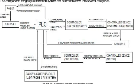
The components for gauge automation system can be broken down into several categories.
Fig.3.Block diagram of general auto gauging system
Fig. 3 shows a block diagram of a general auto gauging system in which a different parts of gauging & automation system is shown. The brief description of the parts are explained below
-Controlled Devices
Fig.4.Pneumatic cylinder
or gauging system. For example the robot can configure fixtures into a wide range of workpiece configurations without operator assistance[6]. As per the design an appropriate system needs to move with respect to other.
Fig.5.Electric motor with gear
Sensing Devices
Sensing mechanisms measure the object processed by the system. Sensing devices can report a presence of the component, states such as on, off, open, closed, etc. The signals sent by sensors are converted into data that can be used by a controller program to make informed decisions based on certain conditions. The measurements obtained make it possible to determine whether the operation or process is proceeding as desired. The signals can be converted at the sensor itself, if it has the appropriate circuitry, by an intermediate protocol converter (translator) or by the system controller. Signal conditioning is manipulating an analog signal in such a way that it meets the requirements of the next stage for further processing. Many applications require environment or structural measurements, such as temperature and vibration, from sensors. These sensors, in turn, require signal conditioning before a data acquisition device can effectively and accurately measure the signal. Key signal conditioning technologies provide distinct enhancements to both the performance and accuracy of data acquisition systems[8].This data is a form of feedback. The sensors used are reed switches, proximity sensors, photo electric sensor etc.
Reed switches are contact type which works on a magnet. Thereed switchis an electricalswitchoperated by
an applied magnetic field. It consists of a pair of contacts on ferrous metal reeds in a hermetically sealed glass envelope. The contacts may be normally open, closing when a magnetic field is present, or normally closed and opening when a magnetic field is applied. The switch may be actuated by a coil, making a reed relay, or by bringing a magnet near to the switch. Once the magnet is pulled away from the switch, the reed switch will go back to its original position. Proximity sensors are the most common and affordable solution for no-touch object detection. The most commonly used proximity sensors are the inductive type which generate an electromagnetic field to sense metal objects passing close to the face. This is usually the easiest sensing technology to apply in applications where the metal target is within an inch or two from the sensor face.
Aproximity sensor as shown in fig. 6is a sensorable to detect the presence of nearby objects without any physical contact. A proximity sensoroften emits an electromagnetic field or a beam of electromagnetic radiation (infrared, for instance), and looks for changes in the field or return signal. Aphotoelectric sensor is equipment used to discover the distance, absence, or presence of an object by using a light transmitter, often infrared, and a photoelectricreceiver. Photoelectric sensors use a beam of light to detect the presence of the component.
I/0 Interface Devices
These are the microprocessor based electronic controllers or simply industrial computers that accept the signals from various sensors as well as command signals from supervisory systems or from human operators. These controllers can be continuous control systems or sequential/logic control depends on the structure of control nature.
Automated measurement technique closes quality control loops in production, in that an early recognizing of possible reasons for rejections together with an analysis results the improvement of manufacturing processes and preventive corrections can be introduced[5]. The controller processes the sensing values and supervisory values and depends on the control structure, it produce the control output to various actuating devices. Input/output (I/O) can give feedback to the manufacturing machine for wrong output of the dimension coming out of the machine. A correction factor is provided to the machine through I/O from gauge readout system. I/O interface devices provide the logical communication link between the controllers and the controlled devices in a system. They are the means of making various devices compatible with the physical and logical structure of the system. I/O interface devices may be separate equipment items, or they may be built in to a controlled device, in which case it would just be considered a feature of the controlled device rather than a separate equipment item.
Some controlled devices require optional or third party I/O interface devices that allow those devices to be integrated into the gauging automation system. A modern type of control device used in automation systems is the Programmable Logic Controller (PLC). PLC is used for automation of typically industrial electromechanical processes, such as control of machinery on factory assembly lines, amusement rides, or light fixtures[1]. PLCs are come with dedicated software so that these are capable of being programmed to perform corresponding control operations.
A specialized I/O interface device that receives standardized commands from a central controller, translates those commands into a new set of commands that is understood by the device it is designed to control, and transmits those commands in the correct form and syntax to the device. This kind of "smart" device may sound like a combination of a controlled device and a controller, but it is more appropriate to call it an I/O interface device.
Controllers
The main function of control systems is to ensure that outputs follow the set points. However, Automation Systems may have much more functionality, such as computing set points for control systems, monitoring system performance, job and equipment scheduling etc.
Fig.7.Solenoid valve
Fig.8.Pneumatic cylinder with sensor & solenoid valve
User Interfaces
User interfaces allow the user to interact with the system by sending information to the controller or by presenting information to the user about the system. A human operator has to monitor sensor gauges and decide whether or not to activate the control elements. The form and capabilities vary widely. Depending on the system and the type of user interface, operator could do any or all of the following: Issue direct commands to the system such as forward the pneumatic cylinder. Obtain feedback from the system such as the position of the component. Program the controller to carry out certain functions automatically, based on time, sequence, or conditions. Some controllers may have an integral user interface like the keyboard on a computer, or there may be remotely located user interfaces with varying degrees of built in intelligence such as wall mounted or handheld keypads or touch panels. Keypad is used to
make changes manually in device[2].
A user interface may accept a variety of user input types. Keystrokes or button presses are the most common modes of entering data. Not all controllers have a user interface. Some specialized controllers may simply use input from sensors or other equipment, and programming to make intelligent decisions based on that input.
Typical user interface devices include:
- Pushbutton
- Panels, with or without visual displays.
- Touch panel
- Displays, with fixed or programmable screen layouts.
- Computer keyboards and monitors.
System Network
Network automation is the use of IT controls to supervise and carry out every-day network management functions. These functions can range from basic network mapping and device discovery to network configuration management and the provisioning of virtual network resources[1].
The system network includes all of the controllers, sensors, wires, cables, adapters, connectors, power supplies, etc. that connect the various system components. This might sound like the simplest part of the system, but it can actually get quite complex. In many systems, this is the area that requires the most planning and can be the most labor-intensive part of a total system installation.
Programming Computer
Some system controllers allow the user to program the system with the system's own user interfaces. Other systems require the use of a separate computer to program the system controller. Still others may allow certain functions to be programmed with the system's own user interfaces, but require a separate computer to program the more advanced functions or change certain basic operating parameters.
VII. GENERAL APPLICATION OF AUTOGAUGING
platform. Then it brings towards gauging station where LVDT probes takes the reading directly. If runout, ovality etc parameters are there, then motorised rotational arrangement can be used. Automation gauging is used where high productivity is required. In mass production system automation helps to carry out the fast & 100% inspection.
VIII. SIMULATION & RESULT
An example of auto gauging system is shown in fig. 9. The loading & unloading is done through robot. For loading a dummy V is provided on which a robot will load the component. Component presence sensors sense the presence of component & give the feedback to I/O interface. An I/O interface then sends the command to controller i.e. to solenoid valve to actuate the cylinder for downward movement. Pneumatic cylinder 1 brings down the component to gauging station & rests it on resting V as shown fig. 9. At the end stroke of the cylinder a sensor which at cylinder 1 sends a single to I/O interface showing that completion of the stroke. Then I/O interface send a command to actuate second cylinder. Pneumatic cylinder 2 brings the component towards the back side where motorized rotational assembly engages with the component. An end stroke sensor sends a single to I/O interface showing that completion of a stroke. Then command goes to motor controller to rotate the motor. The motor rotates the component through 1 revolution or 1.5 revolution as per desired.
After completion of the gauging the reverse sequence takes place by sending signals through sensor to I/O & commands from I/O to controllers. Robot unloads the current component & load next component. System continues the operation.
Fig.9. Auto Gauging System for Shaft
The result gives gauging of following parameters –
1) OD1 through probe P1,P2
2) OD1 ovality through P1,P2
3) OD2 at 2 levels through probe P3,P4 & P5,P6 4) OD2 ovality at two levels through P to P6
5) OD2 taper through probe P3 to P6
6) OD3 through probe P7,P8
7) OD3 ovality through P7,P8
Automation carried out all the gauging process from loading to unloading of the component. A program is made for sequential operation of an auto gauging. A feedback is provided to the manufacturing machine by getting a data from specially developed gauging software when component goes out of tolerance. It needs a special program with I/O interface of the manufacturing machine.
IX. CONCLUSION
With electronic gauging & automation the gauging systems can have more precision, more energy and more speed of operation than possible manually. Moreover using computing techniques, much more sophisticated and efficient operational solutions can be derived and applied in real-time.
A pick and place automated robot is used in many industrial assembly shops. The robot movement can be programmed using a high level interface. In a gauging system, the motion control of the pneumatic cylinder & motors are controlled by a position and speed control system, which uses a separate processor. Another processor is used to manage the other automation aspects.
Automation reduces the cycle time, eliminates human errors & gives more accuracy in gauging of the component.
REFERENCES
[1] Mr. Dheeraj Nimawat, & Mr. Ashish Shrivastava, “Increasing Productivity through Automation” European Journal of Advances in Engineering and Technology, Volume 3, Issue 2, pg. 45-47, 2016.
[2] Tushar Jain & Meenu “Automation and Integration of Industries through Computer Vision Systems” International Journal of Information and Computation Technology, ISSN 0974-2239, Volume 3, Issue 9, pg. 963-970, 2013.
[3] Jeh-Nan Pan “Determination of the optimal allocation of parameters for gauge repeatability and reproducibility study” International Journal of Quality &Reliability Management, Vol. 21, Issue 6, pg. 672-682, 2004.
[4] Dr. Henrik S. Nielsen “Taking Dimensional Metrology to the Next Level” HN Metrology Consulting, Inc., pg. 1-6, Dec. 2010.
[5] P. H. Osanna, N. M. Durakbasa “Trends in Metrology” Problems Of Engineering Cybernetics And Robotics, Volume 53, pg. 15-24, 2002. [6] Z. M. Biy & W. J. Zhangy “Flexible fixture design and automation: Review, issues and future directions” International Journal Production Research, Volume. 39, Issue 13, 2867-2894, 2001.
[7] A. Hähnel, M. Lemaire, F. Rieuneau, & F. Petit “Machines and mechanisms design for reliability”12th IFToMM World Congress, Besançon (France), 18-21, pg. 1-7, 2007.
[8] Shreyas A. Dhole and P. H. Kulkarni “Advanced Automated Electronic Gauging System” International Journal of Science and Research, Volume 4, pg. 352-356, April 2015.
[9] Mr. Rathel R. (Dick) Smith, Dr. Steven W. McCrary & Dr. R. Neal Callahan,“Gauge Repeatability and Reproducibility Studies and Measurement System Analysis: A Multimethod Exploration of the State of Practice” Journal of Industrial Technology, Volume 23, Number 1, pg. 1-12, 2007. [10] Duane S. Boning & James E. Chung “Statistical Metrology - Measurement and Modeling of Variation
for Advanced Process Development and Design Rule Generation” International Conference on Characterization and Metrology for ULSI Technology, NIST, Gaithersburg, MD, March 23-27, Pg. 1-10, 1998.
[11] Dr. B. Sharmila & P. Venkadesan “Automation for Instrument Cluster Panel Testing Using Machine Vision and NI-PXI Hardware-In-the-Loop” International Journal of Advanced Research in Electrical, Electronics and Instrumentation Engineering, Volume 4, Issue 4, Pg. 3773-3778, April 2015.