IJEDR1502230
International Journal of Engineering Development and Research (www.ijedr.org)1407
ton Hydraulic Press Machine. Availability of limited resources for profit oriented manufacturing industries forces optimum use of available overall resources with a basic intention of cost saving approach. Design of a hydraulic press structure is of prime importance keeping in mind the design parameters and performance indicators and their relationship with proper knowledge of existing working conditions and application of load. By FEA implementation, attempts are being made to reduce the thickness of the plates for the C frame structure in order to save the material and its cost.Index Terms - C Frame, Hydraulic press, stiffness, Finite element method.
________________________________________________________________________________________________________
I.INTRODUCTION
Press work is the most widespread among all the devices of forming metals and even some non-metals. In view of its great importance, proper design of these machines, in order to increase their performance and productivity, is considered very essential. The design concept of the press structure is undergoing rapid change, on account of the technological advancements in recent years. In a bid to replace cast iron, welded structures, which are lighter, are being employed. The performance of a hydraulic press depends, largely, upon the behavior of its structure during operation. However, these welded structures are becoming complicated and their accurate analysis, under given loading conditions is quite important to the structural designer. Press design methods have changed within a short span of time from empiricism to rational design methods; with the advent and widespread use of digital computers, it has now become feasible to develop analytical models and computer programs to apply numerical techniques with varying degrees of approximations to the design problems. The research on machine tool structures was stepped up by the application of the finite element method (FEM). This is a more generalized method in which a continuum is hypothetically divided into a number of elements interconnected at nodal points to calculate the strain, displacement and stress. The FEM is preferred because it permits a much closer topological resemblance between the model and the actual machine. It has been only recently employed for press structures. It is desirable in practice that the design analysis should be comprehensive and thorough at minimum cost and time. In complex structures, like hydraulic press welded frames, the concept of finite element method can be applied. Stiffness is the guiding factor for the design of a press frame.
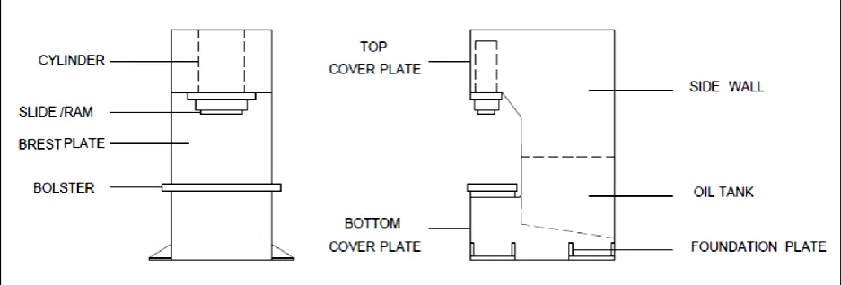
Figure 1 Cross section of Typical C-Frame Press
Table 1 Technical Specification
Type C Frame Hydraulic Press
Model HCP-100
Material ST42-W, Fusion welding
IJEDR1502230
International Journal of Engineering Development and Research (www.ijedr.org)1408
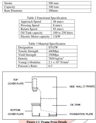
Stroke 500 mm
Capacity 100 tons
Ram Diameter 200mm
Table 2 Functional Specification Approach Speed 48 mm/s Pressing Speed 8 mm/s
Return Speed 85 mm/s
Oil Tank capacity 100 to 250 liters Electric Motor capacity 11kW
Table 3 Material Specification
Designation ST42W
Tensile Strength 460Mpa Yield Strength 250Mpa
Density 7850 kgf/m3
Young’s Modulus 2.1 x 10⁵ N/mm2 Poisson’s Ratio 0.3
II. OBJECTIVE
Figure 2 C Frame Press Details
This project is assigned by HYDROPACK INDIA PRIVATE LIMITED. The objective of this project is to optimize or minimize the thickness of the plates of the side wall or C-Frame, maintaining the top frame deflection of 50 microns. There are 2 side plates, one on each side.
IJEDR1502230
International Journal of Engineering Development and Research (www.ijedr.org)1409
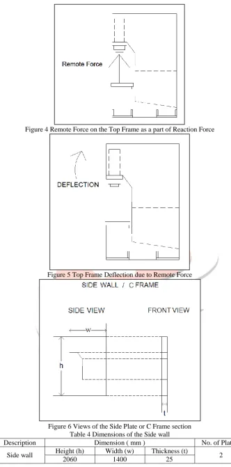
Figure 4 Remote Force on the Top Frame as a part of Reaction ForceFigure 5 Top Frame Deflection due to Remote Force
Figure 6 Views of the Side Plate or C Frame section Table 4 Dimensions of the Side wall
Description Dimension ( mm ) No. of Plates
Side wall Height (h) Width (w) Thickness (t) 2
2060 1400 25
III.METHODOLOGY
IJEDR1502230
International Journal of Engineering Development and Research (www.ijedr.org)1410
is also used. The main purpose of Design Exploration is to identify the relationship between the performance of the product (output parameters) and the design variables (input parameters) and to identify the key parameters of the design and how they influence the performance. The first step of any design simulation is to create the simulation model. The input and output parameters are defined. The next step is to identify the design candidates by creating a response surface. The response surfaces will provide curves or surfaces that show the variation of one output parameter with respect to one or more input parameters at a time. In the process of engineering design, it is very important to understand what are the input variables and how many input variables are contributing factors to the output variables of interest. It is a lengthy process and Designed Experiments help to solve this lengthy process. The Simple Designed experiment used is Screening Design. Hence, this is called Response Surface Optimization which uses Screening Optimization technique. In this technique, we define the design space by giving the minimum and maximum values to be considered for each of the input variables. To compensate the insufficiency of this design, it is enhanced to include center point of each input variable in experimentations. The center point of each input variable allows a quadratic effect, minimum or maximum inside explored space, between input variables and output variables to be identifiable, if one exists. The enhancement is commonly known as response surface design. The Design of Experiment part of the response surface system will create the design space sampling. The type of Design of Experiment used is Box Behnken Design, which is a three level quadratic design.IV.FINITEELEMENTANALYSIS
IJEDR1502230
International Journal of Engineering Development and Research (www.ijedr.org)1411
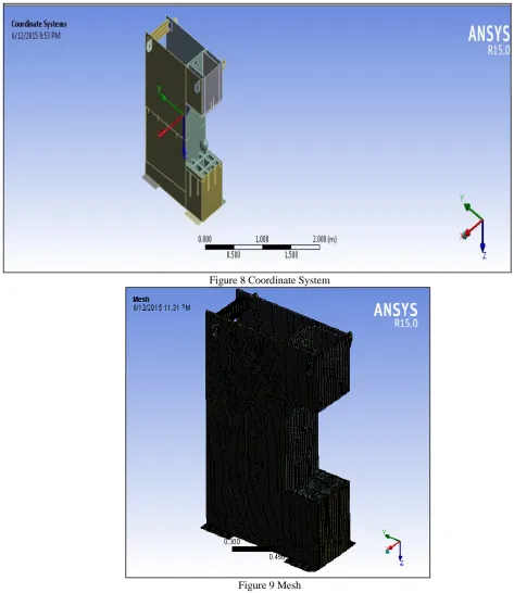
Figure 8 Coordinate SystemIJEDR1502230
International Journal of Engineering Development and Research (www.ijedr.org)1412
Figure 10 Apply Boundary ConditionsFigure 11 Application of Load V.MODALANALYSISRESULTS
IJEDR1502230
International Journal of Engineering Development and Research (www.ijedr.org)1413
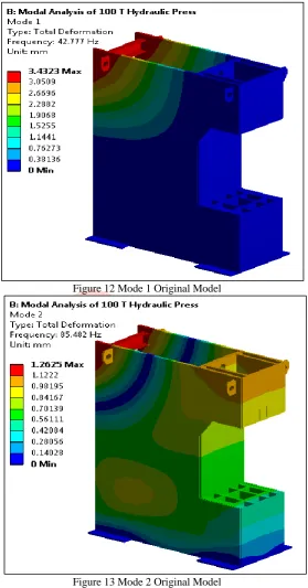
Figure 12 Mode 1 Original ModelIJEDR1502230
International Journal of Engineering Development and Research (www.ijedr.org)1414
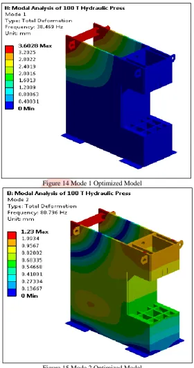
Figure 14 Mode 1 Optimized ModelIJEDR1502230
International Journal of Engineering Development and Research (www.ijedr.org)1415
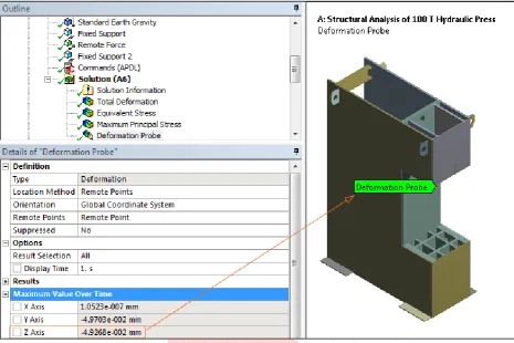
Figure 16 Original Model Top Frame Deformation along z axisIJEDR1502230
International Journal of Engineering Development and Research (www.ijedr.org)1416
Figure 18 Optimized Model Top Frame Deformation along z axisFigure 19 Equivalent Stress of the Optimized Model VII.GRAPHICALRESULTS
P1- Design Candidate Point (Input Parameter) which represents the thickness of the plates of 25mm. P30- Deformation of the Top Frame (Output Parameter) along z axis in mm.
IJEDR1502230
International Journal of Engineering Development and Research (www.ijedr.org)1417
Figure 20 Variation of thickness of 25mm plates with the Deformation of the Top Frame along z axisIJEDR1502230
International Journal of Engineering Development and Research (www.ijedr.org)1418
Figure 22 Variation of thickness of 25mm plates with the Maximum Principal StressVIII.DESIGNOFEXPERIMENT
A designed experiment is a series of runs, or tests, in which you purposefully make changes to input variables at the same time and observe the responses. In industry, designed experiments can be used to systematically investigate the process or product variables that affect product quality. After you identify the process conditions and product components that affect product quality, you can employ direct improvement efforts to enhance a product's manufacturability, reliability, quality, and field performance. In statistics, response surface methodology (RSM) explores the relationships between several explanatory variables and one or more response variables. The main idea of RSM is to use a sequence of designed experiments to obtain an optimal response. This model is only an approximation, but uses it because such a model is easy to estimate and apply, even when little is known about the process. In statistics, Box–Behnken designs are experimental designs for response surface methodology. The Box-Behnken design is an independent quadratic design in that it does not contain an embedded factorial or fractional factorial design. In this design the treatment combinations are at the midpoints of edges of the process space and at the center. These designs require 3 levels of each factor. A Box-Behnken design is a type of response surface design that does not contain an embedded factorial or fractional factorial design. For a Box-Behnken design, the design points fall at combinations of the high and low factor levels and their midpoints.
Table 5 indicates Box Behnken Design of Experiment.
P1- Design Candidate Point (Input Parameter) which represents the thickness of the plates of 25mm. P30- Deformation of the Top Frame (Output Parameter) along z axis in mm.
P31- Maximum Principal Stress (Output Parameter) in MPa. P32- Equivalent Stress (Output Parameter) in MPa.
P41- Geometry mass (Output Parameter) in kg.
The thickness of the plate is varied at 3 levels, low, medium and high level with a difference of 0.5mm and the corresponding variation in response parameters is observed. By analyzing the table of Design of Experiments, an optimal response is chosen.
Table 5 Box Behnken Design of Experiment
Box Behnken D.O.E 25 mm plates
P30 - Deformation Probe Maximum Z Axis (mm)
P31 - Maximum Principal Stress
Maximum (MPa)
P32 - Equivalent Stress Maximum
(MPa)
P41 - Geometry Mass (kg) Candidate Points/ No
of Runs P1 P30 P31 P32 P41
1 18 -0.056093011 90.23639982 85.59301065 1638.775909
2 18.5 -0.055052318 88.42838961 83.83578085 1663.077865
3 19 -0.05405543 86.68340766 82.13983197 1687.379821
4 19.5 -0.053099297 85.01896625 80.52750981 1711.681777
5 20 -0.052181151 83.42367883 78.98312583 1735.983733
6 20.5 -0.051298462 81.89266746 77.5023308 1759.324849
7 21 -0.050448965 80.42373733 76.08448026 1783.626805
8 21.5 -0.050464414 80.84464032 76.9688169 1792.599047
IJEDR1502230
International Journal of Engineering Development and Research (www.ijedr.org)1419
Thickness ( mm ) 25 22 25 22
Mass ( kg ) 497.62 437.9 497.62 437.9
Reduction in Mass ( kg ) - 59.72 - 59.72
IX.CONCLUSION
The thickness of 25mm plates is reduced to 22mm. The criterion of failure used is Von- Mises theory. The Yield Stress of the material is 250MPa. The Equivalent Stress of the Optimized Model is 74.577MPa which is found to be well below the Design Stress of 83.33MPa, assuming a Factor of Safety of 3. This concludes that the optimized design is safe. The deformation of the Top Frame of the Optimized Model is found to be 49.26 microns which is less than the desired limit of 50 microns. The Net component weight reduced which includes both the side walls or C Frames is approximately 120kg. Hence, the percentage of Net component weight reduced is 12%. Hence, the material is optimized. The Raw Material cost is around Rs.50/kg. Hence, cost savings of around Rs. 6000 per machine can be expected. By this, Design Optimization as well as Cost Optimization is obtained.
X.ACKNOWLEDGMENT
We acknowledge the authorities of the institute for their kind support and coordination. XI.REFERENCES
[1] Malachy Sumaila and Akii Okonigbon Akaehomen Ibhadode,”Design and Manufacture of a 30 ton Hydraulic Press”, AU J.T.14 (3): 196-200 (January 2011).
[2] A. G. Naik, N.K. Mandavgade, “FEA Implementation in Analysis and Optimization of Top and Bottom Frame for Hydraulic Cotton Lint Bailing Press”, ISSN-2229-5518, Volume 3, Issue 7, July-2012.
[3] “Design and Analysis of Frame of 63 Ton Power Press Machine by using Finite Element Method” by H N. Chauhan and M P. Bambhania, ISSN-2249-555X,Volume 3, Issue 7, July 2013.
[4] “Analysis of stresses in the corner zone of a C Frame press” by U P.Singh, Eindhoven University of Technology/NL: P.C. Veenstra, Eindhoven University of Technology/NL (1); J.A.H.Ramaekers, Eindhoven University of Technology/NL, 1979. [5] P. D. Murarka and S.P.Sinha,” Computer-Aided Design of Hydraulic Press Structures”, Vol. 10, No. 9, pp. 637-645, 1988.