R E S E A R C H
Open Access
Efficient network coding solutions for
limiting the effect of packet loss
Samih Abdul-Nabi
1,2*, Ayman Khalil
1, Philippe Mary
2and Jean-François Hélard
2Abstract
In traditional store and forward protocols, lost packets have no impact on the delivery of other transmitted packets. With network coding, the impact of a packet loss may affect the decoding of other transmitted packets thus affecting the entire process of communication between nodes. In this work, we propose a new network coding model that allows generating, coding, decoding and transmission activities on the packets. Based on this model, the impact of lost packets on buffering and the complexity at the receiving nodes is studied and two new mechanisms are proposed to allow the recovery of lost packets. Compared to traditional linear network coding protocol, our mechanisms provide a significant performance amelioration in terms of number of transmissions required to recover from packet loss.
Keywords: Network coding, Packet loss, Recovery, Decision model, Algorithm, Closure
1 Introduction 1.1 Motivations
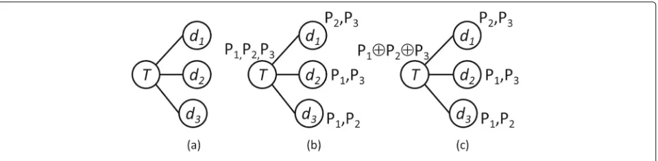
Recent advancements in network coding (NC) imple-mentations have allowed substantial throughput gain in wireless networks. The simple idea of combining sev-eral received or generated packets into one outgoing packet was the starting point for the NC paradigm [1, 2]. Since the publication of [1], researchers have concen-trated on the use of NC for optimizing throughput in multicast networks [1, 3, 4] and for improving network reliability through random linear coding [5, 6]. How-ever, only few published works have considered packet loss and packet loss recovery in the analysis of net-work coding performance [7, 8]. Figure 1 illustrates a NC example with one sender and three receivers over a network with a random packet erasure process. Three cases are considered, a reliable transmission in Fig. 1a, one different packet loss on each link in Fig. 1b, c. To recover the three packets P1, P2, and P3, the scheme in Fig. 1c using NC for the additional retransmission requires only one channel use instead of 3 channel uses with the scheme in Fig. 1b, which does not use NC. Recently, Instantly Decodable NC (IDNC) [9] with its fast decoding potential becomes of major interest for
*Correspondence: [email protected]
1Lebanese International University, Beirut, Lebanon 2INSA de Rennes, IETR UMR CNRS 6164, Rennes, France
real time applications. IDNC uses XOR coding operations and offers instantaneous packet decoding when enough information is available at the receiver.
Another popular NC scheme, known as linear network coding (LNC), has been applied to save packet transmis-sion in wireless networks [3, 10, 11]. Using the example of Fig. 1, LNC consists of improving reliability by ini-tially sending linearly independent combinations of the three packets. Suppose the network eraser rate is 20% for example and that the sender broadcasts four linear combinations of the three packets as follows:
⎛
whereAis the coding matrix andPthe packet vector. In this case, each receiving node can successfully decode all transmitted packets when receiving at least three of the linear combinations. However, the eraser rate is usually variable and unknown and hence the required number of transmissions is very difficult to predict. To guarantee the delivery of all packets, the number of transmitted linear combinations should be large enough to compensate for any loss, consequently, this can compromise the through-put benefit of NC. Thus, one of the main contributions in
Fig. 1Network coding example.aChannel uses,bsix channel uses, andcfour channel uses
the solution detailed later is that it allows, with an opti-mized number of transmissions, to decode all received combined messages independently of the loss rate.
In the traditional store and forward protocols, when a packet is lost, reliability is achieved by requesting the retransmission of that packet. However, with NC, the decoding of new packets relies on previously received ones. Thus, losing few packets might have a domino effect and decoding further packets could become impos-sible. This tradeoff between throughput gain with NC and decoding complexity was studied in [12] and [13], for instance, from a decoding delay point of view.
Motivated by this tradeoff and by the decoding feasi-bility at end nodes, a complete study on the impact of packet loss is conducted in this paper in the case of lin-ear networks [14] and solutions are proposed to deliver all packets in a near optimal number of transmissions.
1.2 Background and prerequisites
Network model: In this paper, the adopted network model is represented as an undirected graphG= (N,E) where the set of nodes N is divided into two exhaustive and mutually exclusive subsets,EN, the set of end nodes andIN, the set of intermediate (or middle) nodes. As illus-trated in Fig. 2, A andBare the two end nodes and ni i= {1, 2,. . .,N−2}are the intermediate nodes. End nodes generate packets to be transmitted to each other via inter-mediate nodes responsible for coding and routing tasks. We denote by packet a newly generated message by an end node∈ EN and bycoded messagea combination of packets coded together using the XOR operation. With-out the lost of generality, NC is assumed to be applied in GF(2). The network in Fig. 2 can be the support of a video conference, data exchange, or other type of information.
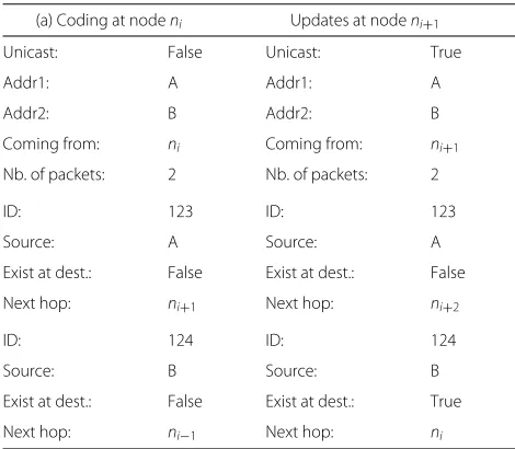
The coded message has its own header identifying the two correlated addresses, the number of coded packets, a header for each packet, and some adaptive memory to help guiding the coded message to its destination as illustrated in Table 1. The payload of the coded message consists of all packets coded together by the XOR oper-ation. By inspecting the adaptive memory, a node in the network can determine whether the message should be broadcasted to all neighboring nodes or unicasted to next hop, i.e., next node. The header of each packet in the coded message identifies its source, its destination, a flag that determines if it exists at destination, and its age.
Definition 1[15] The age of a packet is defined as the number of times the packet contributes to a coded message and the age of a coded message is defined as the age of the oldest packet in the coded message.
Definition 2[15] The maturity of a network is defined as the highest allowed age for all the packets in the network.
Packets reaching the maturity age are prohibited from further coding. The idea is to prevent packets from living forever in the network. Packets in a coded message are address-correlated and only those that are classified as address-correlated are allowed to be coded together [16, 17].
Routing rules: Figure 3 clarifies the setting of the “Exist at dest.” flag. At iterationl, the routing table of nodeni shows that the next hop for packetPAisnj, and the routing table of nodenk shows that the next hop for packetPBis nj. Whenni receives backPAat iterationl+1 within a coded message it knows that a copy ofPAis in its way to
Table 1Routing concept
(a) Coding at nodeni Updates at nodeni+1
Unicast: False Unicast: True
Addr1: A Addr1: A
Addr2: B Addr2: B
Coming from: ni Coming from: ni+1
Nb. of packets: 2 Nb. of packets: 2
ID: 123 ID: 123
Source: A Source: A
Exist at dest.: False Exist at dest.: False
Next hop: ni+1 Next hop: ni+2
ID: 124 ID: 124
Source: B Source: B
Exist at dest.: False Exist at dest.: True
Next hop: ni−1 Next hop: ni
destination thus the “Exist at dest.” flag is set. Similarly, nodenksets the “Exist at dest.” flag of packetPB.
Table 1 shows the header of a newly coded message at node ni. The created message is broadcasted to neigh-boring nodes (unicast is unset) and both packets in the coded message are unknown to their destinationsAand B, respectively, as shown in Table 1a. When the coded message reaches the nodeni+1, the header is updated by the node server and the “Exist at dest.” flag of the packet originated by nodeBis set as shown in Table 1b. Thus, the message continue its way to the destination using uni-cast. The reader is referred to [16] for more details about routing coded messages in NC. The “Exist at dest.” flag, initially set to false, is updated by the routing nodes and set to true whenever a packet is received back within a coded message after being sent to its destination. For decod-ability purposes, the NC scheme guarantees that, in any coded message, at most one, packet is unknown by each destination.
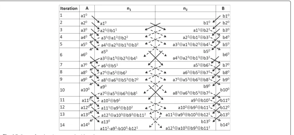
Impact of losing a packet: Figure 4 shows a detailed trace of packets exchanged between end nodesAandB where nodeAgenerates packetsai i = 1, 2,. . .and node Bgenerates packetsbi i= 1, 2,. . .. A maturity value of 3 is set and each packet is upper-indexed by its age. In this
figure, solid arrows indicate a unicasting activity to the next hop and dashed arrows indicate a broadcasting activ-ity of newly coded messages. It is clearly observed that the multiplicity of a packet, given for examplea1, is limited and controlled by the use of aging where the age is visi-ble as superscript on each packet. Packeta1 generated at iteration 1 is removed from all nodes of the network at iteration 7.
In this context, we are mainly interested in the impact of losing a coded message, for example (a1⊕b2) between nodesn2andBat iteration 3, on the decoding capability at nodeB. Failing to receive and decodea1, nodeBwill successively receive undecodable packets.
1.3 Related works
In traditional communication protocols, reliability relies on retransmissions, and end to end reliability is assured by the transport layer of the OSI layered communication stack. Moreover, hop to hop reliability is assured by the PHY and MAC layers by retransmitting unacknowledged packets. Recently, hop by hop transport layer reliability protocols have been developed where intermediate nodes store and recover packets to deliver data more efficiently [18, 19]. With NC, reliability and throughput gain are achieved through linear NC [3, 10] where several packets are linearly combined together and broadcasted into the network. Many works in the literature have dealt with the benefits of NC from the reliability point of view [6, 20].
In [6], authors have presented analytical and numerical results for the performance of end-to-end and link-by-link reliability mechanisms based on automatic repeat request (ARQ), forward error correction (FEC) and NC in a tree topology. Using an access point topology with kreceivers, they demonstrated that the reliability gain of NC compared to ARQ is of(logk). They showed also that allowing intermediate nodes to recover lost packets remains in (logk) while further minimizing the num-ber of transmissions. However, it should be noted that buffering packets in intermediate nodes requires decoding coded messages which might be costly. In our proposed solution, decoding only occurs at end nodes while inter-mediate nodes are only allowed to perform coding activity to minimize the number of transmissions.
Due to lossy wireless channel conditions, recent works have focused on loss recovery taking into consideration
Fig. 4Delivery of packets in a network with no loss
the overhead on the network due to retransmissions. In [21], authors have proposed Codecast protocol suitable to low-loss, low-latency constraint applications such as video streaming. Their work is based on random NC [3] implementing localized loss recovery and path diversity with very low overhead. They demonstrated through-out simulations that codecast achieves a near-perfect packet delivery ratio while maintaining at the same time lower overhead than conventional multicast. Routing and route selection have a major impact on reliability and time delivery.
To reduce loss impact, routing selection mechanisms have been investigated. In [22], overlay routing networks have been proposed to monitor communication between nodes in order to improve routing of packets and pro-vide loss reduction over traditional routing algorithms. Opportunistic routing [23–25] dynamically selects paths based on loss conditions. However, in [26], authors con-ducted a comparison of best-path routing and opportunis-tic routing and found that the benefit of opportunisopportunis-tic routing is much less than commonly believed. It should be well noted that these mechanisms introduce latency on the overall communication time and overhead on the routing nodes. The mechanisms we are proposing are network independent and require no probe from the network.
In the majority of cases, NC is considered as block cod-ing where packets can only be decoded in batches [27]; a packet needs to wait for the arrival of other packets before being able to be decoded. While NC increases throughput and lowers congestion, block decoding may cause major delays and reduction in the quality of service (QoS). Recent works have focused on QoS and proposed
methods to reduce the average waiting time in the buffer of the intermediate nodes [28, 29]. Our work differs from existing works in the sense that we use NC for data exchange activity and not for multicast purposes. With address-correlated NC protocol, no delay is engendered by the coding activity and no packet is delayed waiting for a match. Moreover, instantaneous decoding at end nodes is guaranteed when packets arrive in order. Decoding remains assured in real networks where messages arrive unordered.
1.4 Contributions and paper organization
This work aims to study the impact of packet loss on the decoding capability and resource management. NC schemes where decoding only occurs at destination nodes are investigated. Undelivered packets have impact on some major resources especially buffer size and process-ing time.
Our contributions are summarized as follows:
• A new NC decision model is presented and implemented at each node of the network. The model is used to manage node queues in a way to avoid packet drop due to the limited queue capacity. • The impact of packet loss on the decoding capability at the receiver and the decoding perturbation caused by each loss are investigated and analyzed.
• Two new recovery mechanisms initiated by end nodes are proposed to handle packet loss with NC. (i) The immediate retransmission request (IRR)
mechanism (BCSD) with near optimal number of retransmissions.
The paper is organized as follows; the NC decision model to generate, route, code and decode messages is presented in Sections 2 and 3. In Section 4 different sce-narios for packet loss are investigated and the impact on decoding capabilities and buffering requirements are recorded. Based on the results from Section 4, solutions are proposed in Section 5.
Simulations and results are presented in Section 6 and we conclude with Section 7.
2 A new NC decision model
2.1 General description of the NC decision model
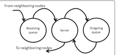
In the considered network, each node consists of a server managing two queues; the receiving queue that holds mes-sages waiting to be coded and the outgoing queue that holds messages waiting to be transmitted (Fig. 5). The receiving queue collects received messages to investigate coding opportunities for address correlated packets which are only allowed to be coded together. On the other hand, the outgoing queue holds messages ready to be transmit-ted into the network in broadcast or unicast modes. The presence of two queues facilitates the scheduling of tasks at the node and reduces the time needed to search for matching messages to be coded.
The state diagram of an intermediate node is shown in Fig. 6. In this diagram, the coding phase is represented by a link from the receiving queue to the server where two or more messages are selected from the receiving queue to be coded together and sent to the outgoing queue. Note that with aging, some mature messages are transferred from receiving to outgoing queue without being coded. The transmission of a message to a neighboring node is done through the server.
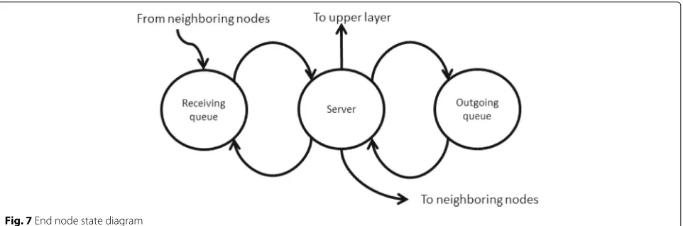
Similarly, the state diagram of an end node is shown in Fig. 7. In this diagram, the decoding phase is represented by a link to the server where one message is selected to be decoded. A message containing several packets can be decoded if a maximum of one of these packets does not exist at destination. When a packet is decoded, it is transferred to the upper layer. If the server is unable to decode a message, the message is returned to the receiv-ing queue and further retries are performed later when
Fig. 5Node model
Fig. 6Intermediate node state diagram
more received packets are available. The generation phase is represented by a link from the server which generates packets according to a model that will be described later. Finally, the transmission of a message to the neighboring node is done through the server.
The receiving queue is used to store all received mes-sages and has a capacity denoted byCrq. We also denote by xrq(t) the number of messages at time t waiting in the receiving queue. The outgoing queue holds messages ready to be transmitted to the network. We denote byCoq andxoq(t)the capacity and the number of coded messages at timetin the outgoing queue, respectively. The server mainly performs one of the following activities: (1) packet generation denoted byg, , coding activity denoted byc, (3) sending message denoted bys, and (4) decoding activity denoted byd. The possible activities at nodes are:
• Sending node activity set ={g,s} • Intermediate node activity set ={c,s} • Receiving node activity set ={d}
Note that, when a node plays more than one role, its set of activity is the union of the activity set associated to each role. For example, the set of activities at an end node is {g,s,d}.
A decision model is needed at each node to select the best activity. Two decision models are adopted for our implementation, a deterministic decision model for inter-mediate nodes and a probabilistic model for end nodes.
2.2 Deterministic model for intermediate nodes
Fig. 7End node state diagram
optimization problem handled at each intermediate node is described in (2).
max yc,ys
yc(t) xr(t)
i=1
mri(t)+ys(t) xo
i=1
moi(t) (2)
subject to yc(t)+ys(t)=1 (3)
yc(t)≥ (
xr(t)−xo(t))−dro Cr
(4)
ys(t)≥ (
xo(t)−xr(t))−dor Co
(5)
yc,ys∈ {0, 1} (6)
In this problem,dro(respectively,dor) is the acceptable difference in number of messages between the receiving queue and the outgoing queue (respectively, between the outgoing queue and the receiving queue), andmri(t)is the amount of time messageihas been in the receiving queue whilemoj is the amount of time messagejhas been in the outgoing queue. The objective of (4) is to forceyc(t)to take the value 1 whenever the difference between the number of messages waiting to be further coded and the number of messages waiting to be transmitted reaches or exceeds dro. Similar objective for (5) by forcingys(t)to be 1 when the difference between the number of messages waiting to be transmitted and the number of messages waiting to be further coded reaches or exceeds the valuedor. Constraint (3) guarantees that the server performs exactly one task at a time. It should be noted that (4) and (5) are built to guarantee that only one of the binary variablesyc(t)and ys(t)is forced to take the value 1, however, both variables are allowed to take the value 0 at the same time which explains the need for (3). In that case, the choice of activity, i.e.,(yc,ys) = (1, 0)or(yc,ys) = (0, 1)is the choice max-imizing (2). The objective function forces the selection of the activity that helps releasing messages with the largest waiting time.
2.3 Probabilistic model for end nodes
A binary variableyi is assigned to each possible activity with i ∈ {d,g,s}. yi can take the values 0 if the activ-ity is not performed and 1 elsewhere. As for the case of intermediate nodes, the server can perform exactly one task at a time. We denote byP(d),P(g)andP(s), respec-tively, the probability of performing a decoding (yd = 1), a generation (yg=1), or a sending activity (ys=1).
The generation of packets is considered as an indepen-dent process from other activities and the decision of the activity to be undertaken at end nodes is performed in two phases. During the first phase, a decision is taken on whether or not the node should generate a packet. If no packets are to be generated, we move to the second phase to select, according to a stochastic decision model, the node activity to be performed.
The stochastic decision model is based on [30] where routing packets are given by some probability functions. For our model, we have the following equations:
P(d) = e
−βxoq(t)
e−βxoq(t)+e−βxrq(t) (7)
P(s) = e
−βxrq(t)
e−βxoq(t)+e−βxrq(t) (8) whereβ is a control parameter andP(d)+P(s) = 1. In (7), the probability of decoding decreases when the num-ber of messages in the outgoing queue increases favoring in this case the sending activity. Furthermore, a similar argument can be given to (8). However, even when the number of coded messages in the outgoing queue (respec-tively, receiving queue) exceeds the number of coded messages in the receiving queue (respectively, outgoing queue), the activity selection process remains stochastic and there is still some probability of selecting the decoding (respectively, sending) activity.
P(d) andP(s) will be, respectively, 0 and 1 if xoq(t) > xrq(t)thus creating a deterministic decision model where the activity is selected according to queues occupation.
Note that, a delayed message at an intermediate node has a domino effect on the delivery of other messages. This imposes a QoS requirement to avoid such effect which is assured by the deterministic model. In revenge, delayed messages at end nodes do not have such effect and the probabilistic model reveals to be flexible and requires less computational time.
3 Activity selection algorithms
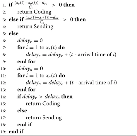
Models presented in Section 2 are used to propose two-low cost algorithms to select the best activity to be per-formed at intermediate and end nodes, respectively. These algorithms are initiated each time the node is requested to select and complete a task. The activity selection at the intermediate node is shown in Algorithm 1.
Algorithm 1 Activity selection algorithm: intermediate nodes
1: if(xr(t)−xo(t))−dro
Cr > 0then
2: return Coding 3: else if(xo(t)−xCr(t))−dor
o > 0then
4: return Sending 5: else
6: delayr =0
7: fori=1 toxr(t)do
8: delayr =delayr+ (t- arrival time ofi)
9: end for
10: delayo =0
11: fori=1 toxo(t)do
12: delayo =delayo+ (t- arrival time ofi)
13: end for
14: ifdelayr >delayothen
15: return Coding
16: else
17: return Sending
18: end if 19: end if
In this algorithm, steps 1 and 3 represent constraints (4) and (5) in the optimization problem presented in (2) and select the activity to perform depending on the occupation of the receiving and outgoing queues. When queues are almost balanced, steps 6 and 17 attempt to maximize (2) helping late packets to be released from the queues and improving QoS.
The activity selection at end nodes is presented in Algorithm 2. In this algorithm, step 2 independently selects the generation activity with a certain predefined
Algorithm 2Activity selection algorithm: end nodes
1: P(generation)=random(0, 1)
2: ifP(generation) <=(Generation-threshold)then
3: return Generation 4: end if
5: P(decoding)= e−βxoq(
t)
e−βxoq(t)+e−βxrq(t)
6: ifP(decoding) <=random(0, 1)then 7: return Decoding
8: else
9: return Sending 10: end if
probability. If no new packets are generated, the code between lines 5 and 10 give higher probability to the activity that balances the receiving and outgoing queues.
4 Packet loss simulation
Algorithms presented in Section 3 are validated by run-ning simulations on a linear network of 6 nodes, i.e., with four intermediate nodes as shown in Fig. 2. Statistics are recorded about the loss impact on decoding opportunity and buffering time at end nodes. For this purpose, the new NC decision model presented in Section 2 is used to built a specific application to simulate the network layer at each node of the network. As example, only the hopn3 →n2 is considered with loss and the packet loss is modeled as an independent and identical Bernoulli distributed pro-cess. The contribution of this section is of twofold; first, to understand the correlation between the packet loss and the number of undecoded packets at the receiver, and sec-ond, to aid to establish a recovery process to minimize the number of retransmissions.
Fig. 8Percentage of undecoded packets with different loss probabilities and different maturities
packets at the receiver is finite and the system resumes receiving decodable packets after each loss.
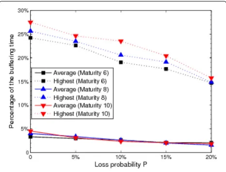
In Fig. 9, the buffering of received packets at the desti-nation nodes is studied. Destidesti-nation nodes need to buffer sent and received packets so that they will be used in the decoding process. Buffering is costly since it requires sig-nificant memory space. Buffering time of a packet is com-puted as the laps of time between the moment the packet was received and the last time the packet was used for decoding other packets. The figure gives the percentage of the buffering time compared to the total communication time versus the loss probabilityP, for three different matu-rity values. Furthermore, for each case, the highest values and the average values are represented. These results show that the buffering time decreases when the loss percentage increases. This is justified by the fact that less decoding occurs when more coded messages are lost. Moreover,
Fig. 9Buffering versus loss percentage
the buffering also varies with maturity. When maturity is increased, more buffering time is required since packets live longer in the network.
4.2 Decoding opportunity
In this section, we study the multiplicity of the lost packets in the network and its impact on the decoding process. By multiplicity, we mean the number of copies of the packet that exist in the network. Recall that, when a packet is coded with others, the coded message is broadcasted into the network creating duplicates of these coded packets. When a packet is lost, other copies of that packet still exist in the network creating undecoding opportunities at the receiver.
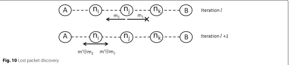
To clarify how end nodes can receive undecodable mes-sages, consider the example shown in Fig. 10. In this example, a coded messagemis created and broadcasted at iterationlby nodenj(shown in the figure asm1andm2 which are identical). Consider now that messagem1is lost andm2reaches nodeni. All packets inm2originated from Aare flagged as exist at destination (“Exist at dest.” flag set to true). Nodeniuses messagem2in further coding activ-ity and broadcasts at itrationl+1 a new coded message m ⊕m2. NodeBcannot decodem
⊕m2since it holds two packets originated byAand unknown toB.
Let us denote byμ ∈ +the maturity age of the mes-sages. Theorem 4.1 sets a boundary on the dissemination of each packet in the network.
Theorem 4.1[15] Given a network G = (N,E) and a maturity scalarμin+. The number of coded messages in the network containing a specific packet is bounded by2μ.
Note that, due to the linear nature of the network, each end node receives a maximum of 22μ messages containing the same packet. This upper bound on the multiplicity of a packet is used in the following theorem to estimate the number of undecoded messages when a packet is lost.
Theorem 4.2Given a network G=(N,E)and a matu-rity scalar μ in +. When a packet loss occurs in the direction of end node E, the estimated number of unde-coded messages that can be received by E as a result of that loss is given by
1
μ+1 μ
i=2
2μ−i (9)
Fig. 10Lost packet discovery
copy of that packet is unicasted in the opposite direc-tion. Consequently, no undecodable messages are received by E. LetPa be a packet with age a, and N
Pa the num-ber of messages received byE that are created starting fromPa. According to Theorem 4.1,N
Pa = 2 μ−a
2 . Refer-ing to the codRefer-ing graph presented in [15], we assume that in a network with maturity μ, there is an equal prob-ability that a lost packet has an age between 0 and μ. The total number of undecoded messages that can be received byEis:
1
μ+1 μ−1
i=1 NPi =
1
μ+1 μ−1
i=1 2μ−i
2 =
1
μ+1 μ−1
i=1
2μ−(i+1)
By takingi+1=j, we can write
1
μ+1 μ
j=2 2μ−j
As an example, a packet loss might lead to receiving four undecodable messages when maturity is set to 6, after which the system resumes receiving decodable messages.
Another important factor that helps in reducing the number of received undecodable messages is related to the model presented in Section 2. Recall that the model allows packets to be transmitted without coding and never waits for a match. A simulation is performed to count the number of packets that are traveling through the net-work without being coded. Figure 11 shows the number of uncoded messages in both queues of each node of the network. End node generates uncoded messages while they receive the lowest percentage of uncoded messages. There is, however, a significant percentage of uncoded packets floating between the nodes of the network. This is in fact due to the following factors:
• Aging: preventing packets from being further coded. • Decision model: forcing packets to be transmitted
without waiting for a match.
Analysis in this section shows an interesting character-istic of NC when it comes to lossy network. The intensive
use of NC, represented by a large maturity value, keeps duplicates of a lost packet in the network and the number of undecodable packets degenerate. One of the advan-tages of aging is that it helps creating mature messages in the network thus preventing coupling with duplicates of lost packets.
5 Proposed mechanisms
Two new mechanisms are detailed in this section. To fur-ther evaluate the performance of these mechanisms, a revised version of the LNC protocol is also presented in this section.
5.1 Immediate retransmission request
The end node receiving an undecodable message is able to identify, by reading the header of the undecoded message, those packets that are flagged as “exist at dest.” but are not in its buffered packets for decoding purpose. Without waiting for a retransmission event from the upper layer (i.e., transport layer) a request of retransmission is initi-ated by the NC protocol for these packets. Note that the retransmission request initiated by the network layer of the receiving node is answered by the network layer of the sending node since it buffers also transmitted packets for
decoding purposes. These requesting and retransmission operations are transparent to the TCP protocol.
Due to delays and unordered arrival of messages at the receiver, one undecodable message is not a sign of packet loss. The receiving node suspects that a loss occurs when undecodable messages remain undecodable for a specific period of time, denoted by ttime (threshold on time) or when receiving a certain number of consecutive undecod-able messages, denoted bytcup(threshold on consecutive undecoded packets).
The IRR algorithm is designed to take into considera-tion the previously menconsidera-tioned concerns. The IRR algo-rithm is shown in Algoalgo-rithm 3 where UM denotes an undecoded message. The algorithm works as follows: ini-tially, consecutive undecoded packets (cup) is set to 0, request retransmission (rr) is set to false and the list of requested packets (lrp) is empty. The algorithm then iter-ates on each entry in the list of undecoded messages. Lines 4 to 11 are dedicated to identify consecutive unde-coded messages and a request for retransmission is initi-ated ifcupreaches a predefined threshold. Lines 12 to 14 investigate the buffering time of each undecoded mes-sage and request retransmission if a threshold on time is reached. The request for packet retransmissions are sent in the header of newly generated packets or immediately if no new packets are available for transmission. Since no buffering of packets is performed in the intermedi-ate nodes, the request for retransmission is sent to the generator nodes. The algorithm is initiated each time the node is about to perform a decoding activity.
Algorithm 3Immediate retransmission request
1: cup=0,i=1,rr=false,rp=∅ 2: whilei≤number of UMdo
3: Add torpthe undelivered packets in UM(i) 4: ifUM(i) and UM(i-1) are consecutivethen
5: Incrementcup
6: ifcup≥tcupthen
7: rr= true
8: end if
9: else
10: cup=0
11: end if
12: ifCurrent time - Receiving time of UM(i)≥ttime then
13: rr= true
14: end if
15: Incrementi 16: end while
17: ifrr= truethen
18: Request all needed packets inrp 19: end if
IRR differs from the ARQ of the end to end transport layer in that IRR is faster to identify lost packets and to initiate a retransmission request. However, it should be noted that IRR does not replace ARQ. As shown in the proof of Theorem 4.2, a packet might be lost without decoding consequences at the receiving nodes. Such a loss can only be detected and requested by the transport layer using ARQ.
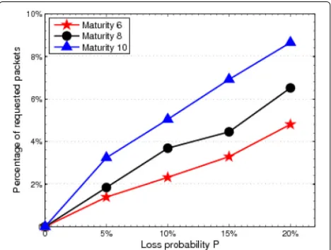
The simulation results of IRR are shown in Fig. 12. The simulation ran with the three values of maturity and with the same conditions than in Fig. 8 of Section 4. Figure 12 shows that the number of requested packets increases with maturity for the same packet loss percentage. Fur-thermore, the number of retransmissions compared to the number of received undecodable messages is presented in Table 2 for two loss percentages, where the undecoded and the requested columns are extracted from the results of Figs. 8 and 12, respectively. Table 2 reveals a reduc-tion in the percentage of requested packets when maturity increases. This is justified by the fact that, with larger maturity, a loss generates more undecodable messages and a retransmission helps also decoding more packets.
5.2 Recovery from packet loss
With NC, recovery from packet loss differs from tradi-tional retransmission protocols since packets are inter-connected together by the mean of coded messages. We showed that losing one packet might lead the way to lose additional packets due to the nature of the coded messages and of the decoding process. For this reason, it is obvious that an efficient algorithm is needed in order to minimize the number of retransmissions.
Due to NC, end nodes receive multiple copies of the same packet as shown previously in Fig. 4. When a loss occurs on a link, a copy of a packet is lost but other
Table 2Percentage of retransmission versus undecoded
Loss probabilityP
10% 20%
Maturity Undecoded Requested Percentage Undecoded Requested Percentage
6 280 205 73.2% 634 486 76.7%
8 577 371 64.3% 954 615 64.5%
10 798 503 63.0% 1381 865 62.6%
copies might still be present in the network. End nodes receive messages that they are unable to decode but might contain such copies. In what follows, we propose algorithms that request the minimal number of retrans-missions in order to retrieve lost packets. Note that retransmitted packets can be coded with newly gener-ated packets leading to further reduction in the number of retransmissions.
Before continuing with the recovery process, we give some definitions and then propose a mechanism to iden-tify the packets to be requested from the sender in order to recover all lost packets with minimal retransmissions.
5.2.1 Closure and covering sets
LetSbe a set of packets andCbe a set of coded messages.
Definition 3When XOR operation is used to code pack-ets together, thesimple closureof S, denoted by S+C, is the set of packets that can be decoded from C using packets in S.
To better understand the simple closure definition, we illustrate the following example.
Let S = {p1,p2,p3} and C = {p1p4,p1p3p5,p4p5p7, p5p6p7,p6p8p9,p7p8p9}.
To build the simple closure ofS, we proceed as follows:
S+C = {p1,p2,p3}
S+C = {p1,p2,p3,p4} using p1p4 S+C = {p1,p2,p3,p4,p5} using p1p3p5 S+C = {p1,p2,p3,p4,p5,p7} using p4p5p7 S+C = {p1,p2,p3,p4,p5,p7,p6} using p5p6p7
Definition 4When linear combination is used to code packets together, thecomplex closureof S, denoted by S++C , is the set of packets that can be decoded, by the mean of Gaussian Elimination, from C using packets in S.
Going back to the previous example, the complex clo-sure ofS, is denoted by:S++C =S+C∪ {p8,p9}wherep8and p9can be obtained by solving the system:
α1p8+α2p9 = R1
β1p8+β2p9 = R2,
where R1 and R2 are the received coded packets and
(α1,α2)tand(β1,β2)tare the corresponding coding vec-tors normally included in the header of the received coded packets.
Definition 5S is acovering setof C if the closure of S includes all packets that are part of the coded messages in C.
Going back again to the previous example, we see that SC++is a covering set ofCbutS+C is not.
Definition 6Abasic covering setof C is a covering set of C with minimal cardinality (having the least number of packets).
5.2.2 Recovery mechanism
The recovery process starts when the receiving end node receives a message that cannot be decoded, i.e., it has more than one unknown packet. At that time, the end node expects to receive additional undecodable packets. Each received undecodable message is XOR-ed with all known packets and the resulting chunk of undecoded packets XOR-ed together is added to an originally empty setC.
starts by building the incident matrix where columns identify the packets inCand rows represent undecoded chunks of messages sorted by receiving time. For the set C = {p1p4,p1p3p5,p4p5p7,p5p6p7,p6p8p9,p7p8p9} the corresponding incident matrixMis
p1 p3 p4 p5 p6 p7 p8 p9
The algorithm then iterates on the incident matrix until the covering set is built. At each iteration, the column with the highest number if 1’s is selected (i.e., highest occur-rence in the undecoded messages) and the corresponding packet is added to the covering set B. Rows with one entry are then removed together with the column of the entry since the corresponding packet can be decoded. The algorithm stops when the incident matrix becomes empty. By applying BCSD to the incident matrixM, the basic covering set found isS+C = {p5,p7,p8}.
Algorithm 4Basic covering set discovery (BCSD)
1: Build the incident matrix 2: Ban empty set
16: ifthere is a row with one entrythen
17: Remove the row and column of that entry
18: end if
19: untilNo more columns can be removed 20: untilMatrix is empty
21: Request packets inBfrom the sender
5.3 Revised linear network coding
To make a fair comparison with both mechanisms pre-sented earlier, a revised version of the LNC mechanism is introduced in this section. The idea of the revised
LNC protocol is to use LNC for unicast and to send enough packets through a lossy network that uses the new NC decision models for intermediate and end nodes, in order to:
• overcome the loss of packets in the links of the network,
• overcome the undecodability of packets at the end nodes.
The revised LNC protocol uses block coding as follows: each sending node groupsbpackets together and sendsb linearly independent combinations of the packets in each group. The cardinalitybof each block and the number of combinations b are determined according to Theorem 4.2 and according to the loss percentage between the end nodes of the network given by
Pn=1−(1−P)N−1, (10)
whereNis the total number of nodes andPis the proba-bility of loss in a link.
OncePn is identified, the sending node needs to send
b =
b 1−Pn
independent linear combinations of the packets of each block to guarantee the delivery of the packets in the block. In order to minimize the number of transmissions, the cardinality of the block should be selected to satisfy 1−bP
n =
In addition, each loss in the network leads, by Theorem 4.2, to haveUn = μ1+1μi=22μ−iundecodable messages that might reach the destination. With Pn as loss per-centage in the network,Un×Pnundecodable messages can reach the end node. To bypass the undecodability problem,bis augmented byPn×b×Un×(1−Pn).
6 Simulation and results
Results are presented in Fig. 13. Traditional store and forward algorithm starts with a total of 50,000 transmissions on a reliable network and ends with an increase of 34% when the loss probability reaches 20%.
Also on a reliable network, revised LNC, IRR, and BCSD start with almost the same number of required transmissions to deliver all the packets. When the loss probability increases, the number of transmissions with the revised LNC increases about 56% when the loss prob-ability reaches 20%. Both NC with IRR and NC with BCSD show an important saving in the number of transmissions compared to the revised LNC. With a loss probability of 20%, NC with BCSD represent a saving of 22% in the number of transmissions over the revised LNC. IRR lightly increases the number of transmissions compared to BCSD.
Figures 14 and 15 show, respectively, the total delivery time and the average delivery time for the three competing mechanisms. The total delivery time is the time elapsed between the transmission of the first packet and the recep-tion of the last one while the delivery time of a packet is computed as the time between the first transmission of the packet and its delivery. In these simulations, each trans-mission from one node to an adjacent one requires 1 ms of time. As shown in Fig. 15, the revised LNC overcomes the proposed mechanisms when it comes to average delivery time. This is justified by the fact that no retransmission is requested. With the revised LNC, the slow increase in the average delivery time is due to the time needed at the receiver to gather enough messages of each block in order to decode the packets of the block. As for our proposed mechanisms, IRR bypasses BCSD when it comes to aver-age delivery time, since IRR reacts immediately when a loss is detected while BCSD waits longer to gather unde-coded messages and reduces the size of the covering set; thus, the number of retransmissions.
Fig. 13Total number of transmissions required to deliver 10,000 packets
Fig. 14Total delivery time of the 10,000 packets exchanged
7 Conclusions
This paper deals with the impact of packet loss in NC. First of all, a new decision model has been presented that prioritizes the tasks that should be performed by each node of the network. The model balances the receiv-ing and the sendreceiv-ing queues of the node and manages to guarantee QoS by releasing late packets to destination. The new model has been used to study packet loss effect on the decoding process at end nodes. Simulations have shown that with the proposed model and with the use of aging, any perturbation caused by losing packets is finite in time and the receiving nodes receive a limited number of undecoded packets. The number of undecoded pack-ets at end nodes has been analytically and experimentally studied under the effect of aging and NC activities and two new mechanisms have been proposed to improve NC per-formance in lossy networks. The first mechanism, called
IRR, immediately requests lost packets when a packet loss occurs and the second mechanism, called BCSD, requests missing packets in a reduced number of trans-missions. Simulation results have shown that in typical cases, both algorithms help reduce by 22% the number of transmissions compared to the revised LNC protocol. Finally, it should be noted that IRR and the revised LNC are more suitable to some applications like video confer-encing where the average delivery time is needed to be reduced while BCSD is more convenient to file exchange where the total delivery time needs to be optimized.
Abbreviations
ARQ: Automatic repeat request; BCSD: Basic covering set discovery; FEC: Forward error correction; IRR: Immediate retransmission request; LNC: Linear network coding; NC: Network coding; QoS: Quality of service
Competing interests
The authors declare that they have no competing interests.
Received: 17 April 2015 Accepted: 30 January 2017
References
1. R Ahlswede, N Cai, SYR Li, RW Yeung, Network information flow. IEEE Trans. Inform. Theory.46(4), 1204–1216 (2000)
2. JK Sundararajan, D Shah, M Médard, M Mitzenmacher, J Barros, Network coding meets TCP: Theory and implementation. Proceedings of the IEEE. 99(3), 490–512 (2011)
3. T Ho, M Médard, R Koetter, DR Karger, M Effros, J Shi, B Leong, A random linear network coding approach to multicast. IEEE Trans. Inform. Theory. 52(10), 4413–4430 (2006)
4. A Agarwal, M Charikar, On the advantage of network coding for improving network throughput. IEEE Information Theory Workshop, 247–249 (2004) 5. T Ho, R Koetter, M Medard, DR Karger, M Effros, inProc. IEEE International
Symposium on Information Theory ISIT, Yokohama, Japan, Jun 29 – July 4. The benefits of coding over routing in a randomized setting, (2003), p. 442 6. M Ghaderi, D Towsley, J Kurose, inINFOCOM 2008. The 27th Conference on
Computer Communications. IEEE. Reliability gain of network coding in lossy wireless networks, (2008), pp. 2171–2179. IEEE
7. S Rayanchu, S Sen, J Wu, S Banerjee, S Sengupta, Loss-aware network coding for unicast wireless sessions: design, implementation, and performance evaluation. ACM SIGMETRICS Perform. Eval. Rev.36(1), 85–96 (2008)
8. DS Papailiopoulos, J Luo, AG Dimakis, C Huang, J Li, inINFOCOM, 2012 Proceedings IEEE. Simple regenerating codes: network coding for cloud storage, (2012), pp. 2801–2805. IEEE
9. S Sorour, S Valaee, Completion delay minimization for instantly decodable network codes. IEEE/ACM Trans. Netw. (TON).23(5), 1553–1567 (2015) 10. S-Y Li, RW Yeung, N Cai, Linear network coding. IEEE Trans. Inform. Theory.
49(2), 371–381 (2003)
11. M Effros, M Médard, T Ho, S Ray, D Karger, R Koetter, B Hassibi, Linear network codes: a unified framework for source, channel, and network coding. DIMACS Series Discrete Math. Theor. Comput. Sci.66, 197–216 (2004)
12. C Fragouli, D Lun, M Médard, P Pakzad, in41st Annual Conference on Information Sciences and Systems. CISS’07. On feedback for network coding (IEEE, 2007), pp. 248–252
13. RA Costa, D Munaretto, J Widmer, J Barros, inIEEE MASS, Atlanta, Georgia, Sep. 2008.Informed network coding for minimum decoding delay (IEEE, 2008), pp. 80–91
14. J Skulic, KK Leung, inIEEE 23rd International Symposium on Personal Indoor and Mobile Radio Communications (PIMRC), 2012. Application of network coding in wireless sensor networks for bridge monitoring (IEEE, 2012), pp. 789–795
15. S Abdul-Nabi, A Khalil, P Mary, J-F Hélard, Aging in network coding. IEEE Wireless Commun. Lett.4(1), 78–81 (2015). IEEE
16. S Abdul-Nabi, A Khalil, J-F Hélard, inThird International Conference on Communications and Information Technology (ICCIT). Routing coded messages in wireless networks (IEEE, 2013), pp. 295–299
17. S Abdul-Nabi, A Khalil, J-F Hélard, in9th International Wireless Communications and Mobile Computing Conference (IWCMC). Efficient network coding packet selection model for qos-based applications (IEEE, 2013), pp. 509–514
18. JF Mingorance-Puga, G Maciá-Fernández, A Grilo, NMC Tiglao, in6th EURO-NF Conference on Next Generation Internet (NGI). Efficient multimedia transmission in wireless sensor networks (IEEE, 2010), pp. 1–8
19. H Lee, Y Ko, D Lee, inFourth Annual IEEE International Conference on Pervasive Computing and Communications Workshops. PerCom Workshops. A hop-by-hop reliability support scheme for wireless sensor networks (IEEE, 2006), p. 5
20. C Fragouli, D Katabi, A Markopoulou, M Medard, H Rahul, inMilitary Communications Conference, 2007. MILCOM 2007. IEEE. Wireless network coding: opportunities & challenges, (2007), pp. 1–8. IEEE
21. J-S Park, M Gerla, DS Lun, Y Yi, M Medard, Codecast: a network-coding-based ad hoc multicast protocol. IEEE Wireless Commun.13(5), 76–81 (2006)
22. DG Andersen, AC Snoeren, H Balakrishnan, inProceedings of the 3rd ACM SIGCOMM conference on Internet measurement. Best-path vs. multi-path overlay routing (ACM, 2003), pp. 91–100
23. S Biswas, R Morris, Opportunistic routing in multi-hop wireless networks. ACM SIGCOMM Comput. Commun. Rev.34(1), 69–74 (2004)
24. K Zeng, W Lou, H Zhai, Capacity of opportunistic routing in multi-rate and multi-hop wireless networks. IEEE Trans. Wireless Commun.7(12), 5118–5128 (2008)
25. S Chachulski, M Jennings, S Katti, D Katabi, Trading structure for randomness in wireless opportunistic routing.37(4), 169–180 (2007). ACM 26. Z Zhong, S Nelakuditi, in4th Annual IEEE Communications Society
Conference on Sensor, Mesh and Ad Hoc Communications and Networks. SECON’07. On the efficacy of opportunistic routing (IEEE, 2007), pp. 441–450
27. W-L Yeow, AT Hoang, C-K Tham, Minimizing delay for
multicast-streaming in wireless networks with network coding. IEEE INFOCOM, 190–198 (2009). IEEE
28. W Chen, KB Letaief, Z Cao, Buffer-aware network coding for wireless networks. IEEE/ACM Trans. Netw.20(5), 1389–1401 (2012)
29. E Drinea, L Keller, C Fragouli, Real-time delay with network coding and feedback. Phys. Commun.6, 100–113 (2013)
30. T Ohira, R Sawatari, Phase transition in a computer network traffic model. APS, Phys. Rev. (E).58(1), 193–195 (1998)
Submit your manuscript to a
journal and benefi t from:
7 Convenient online submission 7 Rigorous peer review
7 Immediate publication on acceptance 7 Open access: articles freely available online 7 High visibility within the fi eld
7 Retaining the copyright to your article