© 2015, IRJET ISO 9001:2008 Certified Journal
Page 1943
STEAM TRAP ANALYSIS AT PROCESS PLANTS
Sreedevi K. P.
M.Tech Student,Energy Systems,Nehru College of Engineering and Research Centre,Kerala,India
---***---Abstract -
In most of the process industries, highpressure steam is utilized for power generation. The
steam is generated in the boilers and transported
through pipe lines to the process plants. During their
travel, loss may occur due to loss of pressure, insulation
failure of the pipe lines and loss of temperature. These
are known as steam network losses. This reduces steam
efficiency and hence the quality of steam gets reduced
at the receiving end. Steam Traps are automatic valves
designed to remove condensate from steam lines and
thus prevent steam loss by trapping the steam. Thus an
efficient and suitable steam trap can reduce steam loss
and hence increase the steam efficiency and quality.
The project is aimed at analysis and rectification of
steam traps in the industry through a detailed study of
steam network. Based on the study, steam loss is
calculated. More the efficient trap exists, the more is the
energy preservation, less the expenditure of fuel and
hence the pollutants discharge to atmosphere. The
results are energy preservings and a taintless,
flourished environment.
Key Words:
Masoneilan approach, steam traps,
temperature gun, ultrasonic leak detector
1. INTRODUCTION
Since industrial revolution, Steam has been used as a
prominent mode of energy transfer. It is produced by the
evanescence of water, the relatively cheap and plentiful
commodity in most parts of the world. Using valves, its
temperature can be varied and fine tuned by the control of
its pressure. It carries relatively large amounts of energy
in a small mass, and when it is encouraged to condense
back to water, high rates of energy flow are obtained, so
that the heat using plant doesn’t have to be unduly large.
Steam is used for generating power and also used in
process industries such as refineries, sugar, paper,
fertilizer and textiles. In the process industries, the high
pressure steam is generated in a boiler. It is distributed
through a network for various process applications, after
conditioning the steam to suit process requirements.
Efficient transmission and utilization of steam is essential,
for maintain the required steam parameters at every
utility point, in the power and process industries. This can
be achieved by keeping the transmission losses and heat
losses to a minimum value and recovery of heat, wherever
possible. The popularity and usefulness of steam to the
industry is due to its following characteristics:
•.Uncostly and inert.
• High heat deportation coefficient.
• Simple control and shifting.
• High specific and latent heat
An energy conscious company is also an environmentally
conscious company. Less energy consumed means less
waste, fewer emission and clean and healthier
environment. Bringing energy and environment together,
lowers the operational cost of the company. Thus, it is
essential that industry work towards energy saving and
clean environment in steam system by properly designing
condensate removal and recovery system. A steam trap is
a device used to discharge condensate and
© 2015, IRJET ISO 9001:2008 Certified Journal
Page 1944
2. MOTIVATION
Steam traps and steam systems represent a large portion
of a manufacturing plant’s total operating cost, but
methods to reduce spending in this area are not clearly
defined. Problems may arise when engineers lack
knowledge regarding such questions as: How do steam
traps affect the steam system and process and product
quality? What are the finest types of traps to use? What
testing methods are used for determining trap failures?
The different considerations involved in selection,
installation, and maintaining steam traps can make it
difficult to recognize what is important and what is not.
Typical information sources such as manufacturers and
the site’s previous experiences may not provide all of the
necessary datas and science. It can be helpful to break
down cost reduction goals into smaller divisions and
pieces and analyze each separately. A common myth is
that the procurement price of a new steam trap is a major
component of system expenditure cost. Because the
impact of running cost is exdtremely higher than
procurement price, it is important to understand the
factors that inversely affect that cost. Total system
operating cost is comprised of multiple components,
including steam loss, generating cost and maintenance
charges. Therefore steam trap failures can affect process
operations and reduce profits. Choosing the right steam
traps can improve reliability and reduce operation cost.
3.
FUNCTIONS OF STEAM TRAP
The job of the steam trap is to get condensate, air and
carbon dioxide out of the system as quickly as they
accumulate. In addition, for overall efficiency and
economy, the trap must also provide:
• Minimal steam loss
• Long life and dependable service. Rapid wear and tear of
parts quickly brings a trap to the point of unreliability. An
efficient trap saves money by minimizing trap testing,
repair, cleaning, down time and associated losses.
• Corrosion resistance: Working trap parts should be
corrosion combatible to resist the damaging effects of acid
or oxygen rich condensate.
• Air venting: Air can be present in steam at any time and
especially on startup. Air must be vented for efficient heat
transfer rate and thus combat system binding.
• Carbon dioxide venting: Venting carbon dioxide at steam
temperature will prevent the formation of carbonic acid.
Therefore, steam trap must function at or near steam
temperature since carbon dioxide dissolves in condensate
that has cooled below steam temperature.
• Operation against back pressure: Pressurized return
lines can occur both by means of design and unintentional
conditions. A steam trap shall be able to sail against the
actual back pressure in its return system.
• Get rid from dirt problems.
4. BREEDS OF STEAM TRAPS
4.1 Thermostatic Traps
These traps sense the temperature difference of entering
fluids. These are designed to unblock for cool fluid and
block for torrid fluid. The pupose is - open for relatively
cooler condensate or air, and close for torrid condensate.
The blocking occurs when the fluid, particulalry hot
condensate, has a temperature greater than or equal to a
certain threshold value as per the design. The torrid
temperature causes a thermostatic element to shift in such
a manner that closes a valve head against a valve seat. This
threshold value is less that of saturated steam, but the
actual specific temperature to open/close varies
© 2015, IRJET ISO 9001:2008 Certified Journal
Page 1945
condensate has a temperature considerably lower thansteam, thermostatic traps are exceptionally good at
venting large amounts of air.
4.2 Mechanical Traps
These traps sense the density difference of entering fluids.
The design is such that it will allow more dense fluids and
block the less dense fluids. The aim is to allow the
discharge condensate, and block the steam. The property
of buoyancy is utilized in selection of allowing mode and
blocking mode of the traps, or more specifically valves.
The buoyant object can be a sealed-round or oblong-float,
inverted bucket or open top bucket depending upon the
applications. The are two classifications of mechanical
traps that operate on the density principle are Float and
Bucket type.
4.3 Thermodynamic Traps
These traps sense the velocity difference of entering fluids
and are designed to discharge condensate, a relatively
slow-moving fluid, and close for flash steam, a relatively
high velocity fluid. When condensate invades the trap
body, it shifts slowly relative to steam and is freely
expelled. When flash or live steam maneuvers across the
underside of the disc, its speed is much higher than water,
and this speed creates a pressure cutback which blocks
the valve head. The valve stays blocked until the control
chamber steam pressure above the valve head cutbacks,
thereby allowing the valve to open.
5. TESTING METHODS OF STEAM TRAP
5.1 Visual Testing
Visual testing includes traps with open discharge, sight
glasses, sight checks, test tees and three way test valves. In
all the cases, the flow and variation of flow is ocularly
turned off, the load on the trap will drop to zero or a very
minimal amount so the visual test will allow in
determining the leakage.
5.2 Sound Testing
Sound testing includes ultrasonic leak detectors,
mechanics stethoscopes, screwdriver or metal rod with a
human ear against it. All these benefit the sound created
by flow to determine the trap function like the visual
method. This method works best with traps that cycle
on/off or dribbles on light load. Traps which have attuning
type discharge patterns are hard to check on soaring flow
rate. Examples are processes, heat exchangers, air
managing coils, etc). Again by diverting condensate flow
ahead of the trap or shutting off a secondary flow as
mentioned under visual testing, the noise level will ground
to zero or a very low level if the trap is operating correctly.
If the trap continues to flow at a soaring rate after
diversion it would be chinking or blowing through.
5.3 Temperature Testing
Temperature testing includes infrared guns, surface
pyrometers, temperature tapes, and temperature crayons.
Typically they are used to gauge the discharge
temperature on the outlet side of the trap. In the case of
temperature tapes or crayon, they are set for a
predetermined temperature and they indicate when
temperature exceeds that level. Infrared guns and surface
pyrometer can detect temperatures on both sides of the
trap. Both the infrared and surface pyrometers require
bare pipe and a clean surface to achieve a reasonable
reading. The temperature reading will typically be lower
than actual internal pipe temperature due to the fact that
steel does have some heat flow resistance. Scale on the
inside of the pipe can also affect the heat transfer. Some of
the more expensive infrared guns can compensate for wall
thickness and material differences. Blocked or turned off
traps can easily be detected by infrared guns and surface
pyrometers, as they will show low or cold temperatures.
© 2015, IRJET ISO 9001:2008 Certified Journal
Page 1946
backing up large amounts of condensate by detecting lowtemperature readings.
6. APPLIANCES OF STEAM TRAP
6.1 For Steam Distribution Piping
The role of steam distribution piping is to reliably supply
steam of the highest reasonable quality to the steam-using
equipment or tracing lines. One of the most important
portrayal of steam traps on steam piping is to help block
the crop up of water hammer. This is done by eclecting a
trap that is designed to avert condensate from pooling.
6.2 For Steam-heated Equipment
Traps that continuously discharge condensate are
typically recommended for these applications. Because the
administration of steam-using process equipment and
comfort heating equipment (like air heaters) is directly
linked to productivity and product trait, it's important to
select a trap that helps shorten start-up time and does not
allow condensate to pool into the equipment, causing
uneven heating, low heat transfer, and other similar
problems. Air venting function is typically required in the
trap to remove air and other non-condensable gases
trapped in equipment and adjacent piping.
6.3 For Tracer Lines
Steam traps for tracer lines have different requirements
because they are typically used with copper piping
(because of its high thermal conductivity) to heat and
maintain the fluidity of viscous fluids at temperatures
below 100 °C (212 °F). A trap that has been fashioned to
counter blockage from copper precipitate and that can
efficiently use the sensible heat of steam/condensate is
desired.
6.4 For Power-drive Equipment
Power-drive equipment includes all turbines used in
compressor, pump, or generator applications, but may also
include steam hammers or wheels. In each power-drive
application, condensate should be eliminated rapidly for
safe and effective operation, and should not accumulate
inside the equipment to avert damage.
7. STEAM LOSS ESTIMATION
The loss of a steam trap is calculated by the equation given
below which was derived from Masoneilan approach.
Lt,y = (1kg/2.2046)FT t,y * FS t,y *CV t,y *ht,y *√{(Pin,t –
Pout,t)*(Pin,t + Pout,t)} ---(1)
Where,
t : steam trap and y: is the period.
Lt,y : Loss of steam (in kg)
FT t,y :failure type factor of ‘t’ during ‘y’.
FS t,y :service factor
CV t,y :flow coefficient.
ht,y :hours for which trap ‘t’ is operating.
Pin,t :pressure of steam at inlet of trap in psia.
Pout,t :outlet pressure of condensate at outlet of trap in
psia.
FS= 2.1*(s-1)/s , where ‘s’ is the capacity factor.
CV=22.1*D2 , where ‘D’ is the diameter of orifice of steam
trap in meters.
CONDITION FT
Rapid Cycling(RC) 0.2
Leaking(LK) 0.25
Blow Through(BT) 1
APPLICATION S FS
Process 1.75 0.9
Drip/Tracer 3.0 1.4
Steam flow Very 2.1
© 2015, IRJET ISO 9001:2008 Certified Journal
Page 1947
8. RESULTS
Table 1: Steam loss computation
Failure Orifice Pin(bar) Appliance Steam
condition dia Of trap loss
(kg/hr)
RC 4.4 4.5 Tracing 2.2
RC 4.4 4.5 Tracing 2.2
RC 4.4 4.5 Tracing 2.2
BT 4.4 4.5 Tracing 11.0
RC 4.4 40 Drain 19.6
LK 4.4 4.5 Tracing 2.7
LK 4.4 4.5 Tracing 2.7
LK 4.4 4.5 Tracing 2.7
RC 4.4 40 Drain 19.6
BT 4.4 18 Drain 44
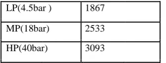
Table 2: Steam Cost/MT in the plant
LP(4.5bar ) 1867
MP(18bar) 2533
HP(40bar) 3093
LP Steam Loss=25.7 kg/hr MP Steam Loss=44kg/hr HP
Steam Loss=39.2kg/hr Total steam loss=108.9kg/hr
Monetary loss calculation (Lacs/annum): LP monetary
loss=4.14 Lacs/annum. MP monetary loss=9.6
Lacs/annum.
HP monetary loss=10.4 Lacs/annum.
9. CONCLUSION
Steam traps serve the basic purpose of maintaining the
aspect of steam at utilization end. At the same time it is
necessary that these traps should be properly selected,
designed and maintained so as to minimize the loss of
steam in the steam network. Appropriate selection of traps
as per the steam network parameters and routine
maintenance of traps are necessary to mitigate the steam
loss. Thus in addition to maintaining quality steam at
utilization end, efficient trapping paves way for monetary
saving and reduction in Green House Gas (GHG) emissions
by saving steam & thereby reducing the fuel consumption.
REFERECES
[1] YP Abbi and Shashank Jain, Hand book on energy
audit and environment management(TERI Press, New
Delhi, 2009).
[2] S.M.Khosla, Energy conservation efficiency and
management in industry and plants (BICS publisher, New
Delhi).
[3] Manual on energy efficiency at design stage