Performance Analysis Of Hybrid Energy
System With Five Level Inverter Fed Induction
Motor Drive
Y ANILKUMAR SHETTY M-tech Scholar
Department of Electrical & Electronics Engineering, Scient Institute of Technology, Ibrahimpatnam;
Rangareaddy(Dt); Telangana, India. Email:yanilkumar992@gmail.com
K. SREEPAL REDDY
Assistant Professor
Department of Electrical & Electronics Engineering, Scient Institute of Technology, Ibrahimpatnam;
Rangareaddy (Dt); Telangana, India. Email:sreepalpid@gmail.com
Abstract: This concept describes the Simulation and analysis of hybrid energy system consisting of wind and solar PV system. The wind and solar PV system are connected to the common load through DC/DC Boost converter. Generally, in low radiation PV array system inverter gives the lower voltage than the rated voltage which affects the power quality. It is overcome by using Battery Energy Storage System. In the stand-alone mode the converter needs to maintain constant voltage and frequency regardless of load imbalance or the quality of the current, which can be highly distorted, if the load is nonlinear. Simulation results show that the proposed hybrid system has the potential to meet the electricity demand of an isolated system. This concept has described a hybrid energy system with variable speed wind generation, photovoltaic system with power electronic interface under stand-alone mode. In the stand-alone mode the performance of the system is evaluated for various wind speeds and various irradiation levels and the performance was analyzed. Due to variations in wind speed and solar irradiation AC voltage varies. Battery system is used to maintain the balance between the source and load. This can be extended for Induction Motor drive Application i.e, Modeling and Simulation of Solar PV Wind Hybrid System for Induction Motor Drive Application.
Keywords-- Renewable energy, photovoltaic, Wind energy conversion system, hybrid energy system, inverter
I INTRODUCTION
Due to the critical condition of industrial fuels which include oil, gas and others, the development of renewable energy sources is continuously improving. This is the reason why renewable energy sources have become more important these days. Few other reasons include advantages like abundant availability in nature, eco-friendly and recyclable. Many renewable energy sources like solar, wind, hydrel and tidal are there. Among these renewable sources solar and wind energy are the world’s fastest growing energy resources. With no emission of pollutants, energy conversion is done through wind and PV cells. Day by day, the demand for electricity is rapidly increasing. But the available base load plants
are not able to supply electricity as per demand. So these energy sources can be used to bridge the gap between supply and demand during peak loads. This kind of small scale stand-alone power generating systems can also be used in remote areas where conventional power generation is impractical. In this paper, a wind-photovoltaic hybrid power generation system model is studied and simulated. A hybrid system is more advantageous as individual power generation system is not completely reliable. When any one of the system is shutdown the other can supply power [1]. The entire hybrid system comprises of PV and the wind systems. The PV system is powered by the solar energy which is abundantly available in nature. PV modules, maximum power point tracing systems make the PV energy system. The light incident on the PV cells is converted into electrical energy by solar energy harvesting means. The maximum power point tracking system is used, which extracts the maximum possible power from the PV modules. The Wind turbine, gear box, generator and an AC – DC converter are included in the wind energy system. The wind turbine is used to convert wind energy to rotational mechanical energy and this mechanical energy available at the turbine shaft is converted to electrical energy using a generator. To coerce the maximum power from wind system we used a maximum power point tracing system. [2]
connected by a conductor anelectric current will start flowing. This electricity is used to power a load.A single cell generates very low voltage (around 0.4), so more than one PV cells can beconnected either in serial or in parallel or as a grid (both serial and parallel) to form a PVmodule.A photovoltaic array is simply an interconnection of several PV modules in serialand/or parallel. The power generated by individual modules may not be sufficient to meetthe requirement of trading applications, so the modules are secured in a grid form or as anarray to gratify the load demand.
Generally a wind turbine consists of a set of rotor blades rotating around a hub, agearbox-generator set placed inside the nacelle.Based on axes the wind turbines are categorized into two kinds: the vertical axis wind turbine and the horizontal axis wind turbine.
Induction motors can be described as a three phase, self starting constant speed ac motors. The reason of describing induction motors as constant speed is because normally these motors have a constant speed depending on the frequency of the supply and the no of windings. In the past it was not possible to control the speed of the induction motors according to the need. That’s why their use was limited and despite having many a motors they advantages over dc motors they could not be used because of this disadvantage. But at the field of drivers have improved due to the availability of thyristors or SCRs, power transistors, IGBTs and GTOs the variable speed induction motor drives have been invented. Though the cost of these drivers are more than dc driver, but still the use of induction motors are increasing and they are replacing dc motors because of their advantages.
II.PROPOSED HYBRID SYSTEM
The proposed system consists of a PV array and Inductiongenerator-driven Wind energy conversion system meeting the requirement of aInduction motor load. The PV system consists of PV arrays andcorresponding DC/AC converter modules. Generally,according to the sunlight conditions, the maximum powerpoint tracking control mode is adopted for PV system,which aims to utilization of solar energy [4]. A H-Bridgeinverter is used to connect the load to the hybrid system.Batteries are used as backup option to store the powerwhen the power production exceeds the demand. Thesupply from the battery is needed during peak hours whenpower demand is higher than the production.
Fig I : Schematic diagram of Hybrid System
III. MODELLING OF VARIOUS RENEWABLE ENERGY SYSTEMS:
This section presents mathematical models of energy sources and power electronic converters used in the proposed hybrid energy system
A. Modeling of Photovoltaic System:
The PV system consists of PV arrays and corresponding DC/AC converter modules. Generally, according to the sunlight conditions, the maximum power point tracking control mode is adopted for PV system, which aims toutilization of solar energy. [4]. When exposed to sunlight, photons which energy greater than the band gap energy of the semiconductor are absorbed and create some electron hole - pair proportional to the incident radiation. The equations of the output current is given by
(1)
Where
(2)
(3)
The I-V characteristics of a solar cell is given by
(5)
Ipv is the current generated by the incident of light, 10 is thediode reverse bias saturation current, VT
= . . is the thermal voltage of PV module having Number of cells ( S)connected in series; Rs starting resistance, Isc is the short circuit current, q is the electron charge; K = 1.38xl0-23 is the Boltzmann constant; T is the temperature of the p-n junction and A = 2 is the diode ideality factor. The output of the current source is directly proportional to light falling on the cell. Naturally PV system exhibits a non-linear Current – Voltage (I-V) and Power - Voltage (P-V) characteristics which varywith the radiant intensity and cell temperature. Thedependence of power generated by a PV array with changing atmospheric conditions can readily be seen in the I-V and the P-V characteristics of PV arrays.
Fig 2 : Equivalent circuit of Photovoltaic system
B.Modelling of Wind System:
The wind turbine depending on the flow of air in the rotor consists of two or three blades mechanically coupled to an electric generator. The power captured by the wind turbine is given by relation
(6)
P is the air density, which is equal to 1.225 kglm3, Cp isthe power coefficient, Vw is the wind speed in (m/s) and A isthe area swept by the rotor inC m2).The amount of aerodynamic torque Tw in (N-m) is givenby the ratio between Ihe power extracted from the wind Pw and turbine rotor speed Ww in (rad /s) as follows
(7)
C. Modelling of Battery:
The storage capacity at any given time (t) is expressed as
(8)
WhereCbat (t) and Cbat(t_l)is the available battery
capacity at time (t) and (t-I).Ppvis power generated by Photo voltaic system ,Pwg is power generated by wind turbine generator, P10ad (t) is power consumed at
load t, t is simulation step (t = 1 hrs),
ncad is
efficiency of AC/DC converter and
nb is
batterycharging efficiency whichdepends upon charging current and may vary from 0.65 - 0.135. When wind alone cannot meet the power demand but combining with PV can, i.e.,ninvPwg(t) + Ppv(C) ≥P'oad (t). In such case the excess power ifavailable is used in charging the battery. Battery storage capacity in such case is given by:(9)
D. DC-DC Boost Converter:
DC-DC boost converter is a most efficient topology whichensures good efficiency along with low cost. A DC-DC boostconverter is connected next to full-wave bridge rectifier toraise the voltage of the diode rectifier. A capacitor C 1 isconnected across rectifier to lessen the variation the rectifiedAC output voltage waveform from the bridge. Figure 3 showsthe arrangement of the DC-DC boost converter circuit.
The model of the boost converter is needed to simulate and analyze the behaviour. The input and output voltage of the boost converter under an ideal condition can be related as
10)
Vi is the input voltage, Vo is the output voltage and 0 isduty cycle .given the value of 0, it is possible to find the minimum values for inductance and capacitance using the equations given below.
(11)
(12)
Where, Vr is the ripple voltage, Ro is the output resistance and f is the switching frequency. An important consideration in DC-DC converters is the use of synchronous switching which replaces the flywheel diode with a power IGBT with low "on" resistance, thereby reducing switching losses. This isachieved by using a Pulse Width Modulation (PWM) switched mode control design or PWM. The PWM performs the control and regulation of the total output voltage . If the semiconductor device is in the off-state, its current is zero, and hence, its power dissipation is zero. If the device is in the onstate, the voltage drop across it will be close to zero, and hence, the dissipated power will be very small. The mostcommon strategy for controlling the power transmitted to theload is the Pulse Width Modulation (PWM).
E. H- Bridge Inverter:
Fig.4 shows a five level cascaded H-bridge multilevelinverter. The converter consists of two series connectedH-bridge cells which are fed by independent voltage sources.The outputs of the H-bridge cells are connected in series suchthat the synthesized voltage waveform is the sum of all of theindividual cell outputs. The output voltage is given byV=V1 +V2Where the output voltage of the first cell is labeled V1 and theoutput voltage of the second cell is denoted by V2. There arefive level of output voltage ie 2V, V, 0, -V, -2V.The
mainadvantages of cascaded H-bridge inverter is that it requiresleast number of components, modularized circuit and softswitching can be employed.
Fig 4. Five level cascaded H-bridge multilevel inverter.
The Switching sequence for a chb inverter is as follows as shown in table I
TableI
IV. INDUCTION MOTOR
retains the torque capability of the machine at the same value. But at lower frequencies, the torque capability decrease and this drop in torque has to be compensated for increasing the applied voltage.Any reduction in the supply frequency without a change in the terminal voltage causes an increase in the air gap flux. Induction motors are designed to operate at the knee point of the magnetization characteristic to make full use of the magnetic material. Therefore the increase in flux will saturate the motor. This will increase the magnetizing current, distort the line current and voltage, increase the core loss and the stator copper loss, and produce a high pitch acoustic noise. While any increase in flux beyond rated value is undesirable from the consideration of saturation effects, a decrease in flux is also avoided to retain the torque capability of the motor. Therefore, the variable frequency control below the rated frequency is generally carried out by reducing the machine phase voltage, V, along with the frequency in such a manner that the flux is maintained constant. Above the rated frequency, the motor is operated at a constant voltage because of the limitation imposed by stator insulation or by supply voltage limitations.
V. SIMULATION RESULTS
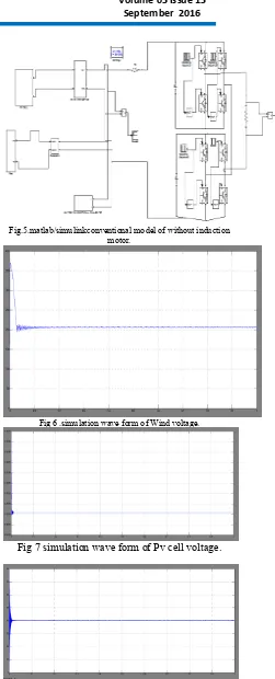
A hybrid system consisting of I.SMW and ISOWp Solar PV system is simulated . The parameters of the Wind turbine and Solar PV system are given in Table III and IV. The subsystem of the Wind and Solar PV system are given in Fig 4 and 8 respectively. The load is connected to the hybrid system through an inverter with the rating of 1.3 MVA. PWM with carrier frequency of 1000 Hz is given across the gate circuit of the H-Bridge inverter. Figure 11 shows the developed MATLAB/Simulation model of hybrid renewable energy system. First the system is simulated with wind and Solar alone and the performance of the individual generators are evaluated. Next the performance of the hybrid system is evaluated under different load conditions.
Fig.5.matlab/simulinkconventional model of without induction motor.
Fig 6 .simulation wave form of Wind voltage.
Fig 7 simulation wave form of Pv cell voltage.
Fig 9 simulation wave form of Inverter Voltage
Fig.10.matlab/simulinkproposed model of with induction motor.
Fig 11 simulation wave form of Capacitor voltage dc machine
Fig 12.simulation wave form of speed
Fig 13 simulation wave form of torque
Fig 14 simulation wave form of Winding currents VI. CONCLUSION
This paper has described a hybrid energy system with variable speed wind generation, photovoltaic system with power electronic interface under stand-alone mode. Computer simulation was conducted using MATLAB/SIMULINK. In the stand-alone mode the performance of the system is evaluated for various wind speeds and various irradiation levels and the performance was analyzed. Due to variations in wind speed and solar irradiation AC voltage varies. Battery system is used to maintain the balance between the source and load. The performance of the developed system with proposed Induction Motor drive characteristics of current, speed and torque can be evaluated in MATLAB/SIMULINK platform and the results are presented.
VII. REFERENCES
Hybrid Solar - Wind Electric Power System Interface to Grid System, "International Journal of Research in Engineering and Advanced Technology, vo!.3, Issue
4, August 2013. pp.4107-4116
[4] UVinatha,Vittal K P,"Grid Integration of Wind and Photovoltaic Hybrid Energy System,"Journal of Electrical Engineering,National Institute of Technology, Karnataka, Surathkal, India. pp.1-6 [5] F.Valenciaga and P.F. Puleston, "Supervisor Control for a Stand-alone hybrid Generation System using Wind and Photovoltaic Energy" IEEE transactions on energy conversion, vol. 20, No.2, June2005.pp.197-207
6] ChaitanyaMarisarla, K.Ravi Kumar, "A Hybrid Wind and Solar Energy System with Battery Energy Storage for an Isolated System, "Journal of Engineering and Innovative Technology, voI.3, Issue
3, September 2013. Pp.99-104.
[7] Cultura A.B,Z.M. Salameh,(2011) "Modelling and simulation of a wind turbine-generator system" ,IEEE Power and Energy Society General Meeting,
pp 1-7
[8] Hasnaoui 0 B K,1. Belhadj,M.Elleuch,(2006) "Low voltage ride through performances of direct drive permanent magnet synchronous generator wind turbine, "CERE-06, Hammamet, TUNISIA.pp.73-83 [9] KarrariM,RosehartW,Malik OP. "Comprehensive control strategy for a variable speed cage machine wind generation unit. IEEE Trans Energy Convers
2005; 20(2):415-423
[10] Wai RJ, Lin CY, Chang YR ."Novel maximum power extraction algorithm for PMSG wind generation system. lETElectr Power Appl 2007;
1(2):275- 283.
[II] R.Srinivasan, M.Yogaselvi, "Stand-alone Hybrid Wins Solar Power Generation System Applying Advanced Power Control Techniques, "UAREEIE. VoI.3, Issue 2, April 2014 pp.627-636 [12] RJeevajothi, DDevaraj, "Voltage stability enhanced using an adaptive hysteresis controlled variable speed wind turbine driven EESG with MPPT, Journal of Energy, vol . 25 No 2 , May 2014
pp. 48 - 60.
[13] R.Jeevajothi, D.Devaraj,"Transient Stability Enhancement using Variable Speed Wind Turbine with Direct Drive Synchronous Generators, International Journal of Computer and Electrical Engineering, vol.4. No.2. April 2012. pp.231-23
Author’s details:
Y ANILKUMAR SHETTY received B.TECH degree from Arjun College of Technology and Sciences, Batasingaram, Rangareddy (JNTUH) in the year 2014.M Tech in the stream of power electronics,Scient Institute of Technology, Ibrahimptnam, Rangareddy(dist) (JNTUH).
Email: yanilkumar992@gmail.com