DOI: 10.15662/ijareeie.2014.0307031
Dual Band Aperture Coupled Stacked
Microstrip Patch Antenna for WLAN
Gunjan
1, Amanpreet Kaur
2PG Student [ECE], Dept. of ECE, Thapar University, Patiala, Punjab, India 1
Assistant professor, Dept. of ECE, Thapar University, Patiala, Punjab, India 2
ABSTRACT:This paper presents a dual band aperture coupled stacked microstrip antenna with the introduction of an air gap 3 mm between the ground plane and the upper layer substrate for WLAN applications. The nominal antenna has
– 10 dB return loss bandwidth of 134.8 MHz and 384.9 MHz at lower band resonant frequency of 3.905 GHz and upper band resonant frequency of 5.36 GHz respectively. The gain of the antenna is greater than 5 dB, also the directivity is greater than 5 dBi and VSWR value is less than 2 for both the operating frequencies, which makes it a suitable choice to be used at the frequencies bands of WLAN.
KEYWORDS: Aperture coupling, microstrip antennas, stacked microstrip, WLAN.
I.INTRODUCTION
Microstrip patch antennas are very popular among various types of antennas due to their planar configuration, low profile, conformability, low cost and ease of fabrication. The aperture coupled technique to feed the microstrip patches provide the advantage of isolating spurious feed radiations by the use of a common ground plane [1]. This technique also avoids the problem related with the large probe self reactances and it facilitates the construction process because no soldering is required as in probe fed technique [2]. The aperture coupled technique provides lower parasitic radiation and greater radiation pattern symmetry. The variations in the dimensions of the aperture facilitates impedance matching of the antenna. It is well known fact that the coupling of several resonances lead to an increase in bandwidth, which is desirable for applications in the telecommunications field [3].
The primary barrier to implement the microstrip antennas in many applications is their narrow bandwidth and to overcome this limitation much work has been devoted to increase the bandwidth. There are various bandwidth enhancement techniques one of which is the use of a non resonant aperture (large aperture) with a thick substrate [4]. But this method has a disadvantage of large amount of radiation production by the aperture, which leads to a radiation pattern having poor front to back ratio. The other bandwidth enhancement techniques include using decreasing dielectric constant, parasitic patches, cutting slots or notches like U-slot, using air substrate, E-shaped, H-shaped patch antennas [5],[6],[7],[8]. The another bandwidth enhancement technique that has been extensively used is stacked patches, in which a parasitic element (stacked patch) is placed over the driven element (lower patch) and the electromagnetic coupling between the parasitic element and the driven element increases the impedance bandwidth [9],[10].
II.ANTENNA DESIGN
An aperture coupled microstrip patch antenna resonating at two frequencies is designed using stacking. Stacking is a technique to achieve the dual band behavior and to increase the impedance bandwidth of the antenna. It involves a multilayered structure consisting of number of dielectric substrates and patches. In it parasitic elements (or stacked patches) are placed over the driven element (or the main patch). The electromagnetic coupling between the parasitic element and the driven element increases the impedance bandwidth. Furthermore an air gap of 3 mm has been introduced between the ground plane and the upper layer substrate to increase the bandwidth of the antenna. FR-4 is the material used for antenna substrate (for both the upper substrate layers) and feed substrate (the lower substrate layer). The material has a thickness (h) of 1.6 mm and dielectric permittivity εr of 4.4 with tangent loss component tan δ
as 0.0009. The antenna structure has a bottom patch of rectangular shape over the substrate material supported by the ground plane. The top patch of the antenna is of a rectangular shape having a rectangular slot of dimensions exactly same as the dimensions of the bottom patch. The dual band antenna is fed through an aperture cut in the ground plane coupled to a 50 Ω microstrip line under the feed substrate. The side view of the antenna showing various layers organizations with placement of waveguide port is shown in Figure 1.
Figure 1 Side view of the Dual Band ACSMPA
Figure 2 depicts the every layer view of the antenna with labelled dimensions. Figure 2 (a) depicts the rectangular top patch of the antenna structure having rectangular slot in it placed over upper layer substrate 1 followed by rectangular bottom patch placed over upper layer substrate as shown in Figure 2 (b), supported by the ground plane having a rectangular aperture shown in Figure 2 (c), below the ground plane there is lower layer substrate, on the rear side of which there is microstrip feed line of 50 ohms as shown in Figure 2 (d).
The front view of the antenna is shown in Figure 3.
Figure 3 Front view of the antenna showing position of the bottom patch below the slot cut in the top patch
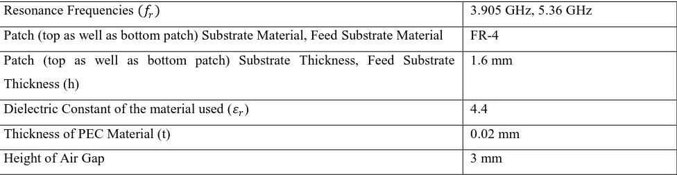
The design specifications of the dual band ACSMPA has been given in Table 1.
Resonance Frequencies 𝑓𝑟 3.905 GHz, 5.36 GHz
Patch (top as well as bottom patch) Substrate Material, Feed Substrate Material FR-4
Patch (top as well as bottom patch) Substrate Thickness, Feed Substrate
Thickness (h)
1.6 mm
Dielectric Constant of the material used (𝜀𝑟) 4.4
Thickness of PEC Material (t) 0.02 mm
Height of Air Gap 3 mm
Table 1 Design specifications of the proposed dual band ACSMPA
Also the various dimensions of the antenna has been calculated by the design equations from C A Balanis [1]. The dimensions of the top patch, bottom patch, ground plane, substrate layers, slot and the feedline of the designed dual band antenna has been given in Table 2.
Parameters Description Values
L Length of the Top Patch 19.72 mm
W Width of the Top Patch 25.75 mm
𝑳𝒃 Length of the Bottom Patch 9.7 mm
𝑾 𝒃 Width of the Bottom Patch 16.44 mm
𝑳𝒈 Length of the Ground Plane 29.32 mm
𝑾𝒈 Width of the Ground Plane 35.35 mm
𝑳𝒔 Length of the Aperture in the ground plane 18 mm
𝑾𝒔 Width of the Aperture in the ground plane 1.6 mm
𝑳𝒇 Length of the Feedline 22.36 mm
𝑾𝒇 Width of the Feedline 3 mm
III.SIMULATION RESULTS
CST Microwave Studio 2010 has been used to simulate the proposed dual band aperture coupled microstrip patch antenna with an air gap and various simulation results like return loss, smith chart, VSWR and farfield patterns of the gain and directivity of the antenna has been observed. The S11 versus frequency plot of the antenna also shows two
dips indicating dual frequency operation of the antenna at the resonance frequencies of 3.905 GHz and 5.36 GHz. The value of reflection coefficients Ʈ are 0.10301 and 0.054688 at the corresponding resonance frequencies as seen from the Figure 4.
Figure 4 S-parameter (Ʈ or reflection coefficient) versus frequency plot of the proposed dual band ACSMPA
The return loss 20 log10 Ʈ values are −25.242 dB and −19.742 dB at the corresponding resonance frequencies. The
S11 parameter represents the power reflected from the antenna. The whole power is reflected from the antenna and
nothing is radiated for S11= 0 dB. S11= −10 dB indicates 10% of the power is reflected. The bandwidth of the dual
band antenna can be calculated from the return loss versus frequency plot. The bandwidth of the antenna is the range of frequencies over which the return loss is larger than −10 dB and it corresponds to a VSWR value of 2. The measured
−10 dB bandwidth of the designed antenna is 134.8 MHz and 384.9 MHz at the lower resonant frequency of 3.905 GHz and the upper resonant frequency of 5.36 GHz respectively as seen from Figure 5.
Figure 5 Return loss 𝑺𝟏𝟏 versus frequency plot of the proposed dual band ACSMPA
Figure 6 Comparison of return loss plot of the dual band and proposed dual band ACSMPA
The smith chart of the dual band antenna has been shown in Figure 7 which depicts the impedance values (resistance as well as reactance) of the antenna at the marked frequency values. The almost real value of the impedance (with a very small reactance) at the resonance frequencies indicates the antenna requires lesser tuning to be done to match the antenna’s impedance with the transmission line.
Figure 7 Smith Chart of the proposed dual band ACSMPA
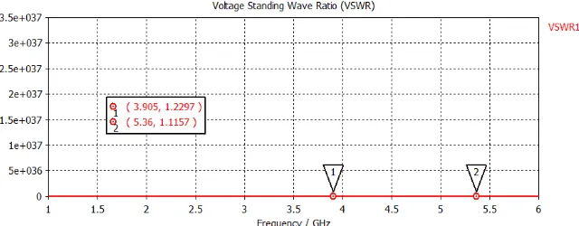
The VSWR versus frequency plot of the dual band antenna has been shown in Figure 8 which depicts the VSWR values at both the resonance frequencies. The antenna achieves a VSWR value of 1.2297 at the lower band frequency of 3.905 GHz and 1.1157 at the upper band frequency of 5.36 GHz.
The polar plot of the directivity with the elevation angle (θ degrees) at the azimuth angle (ɸ) phi equal to 90 degrees of the dual band antenna with stacked technology at both the resonance frequencies of 3.905 GHz and 5.36 GHz is shown in Figure 9(a), (b)
Figure 9 Polar plot of the directivity of the dual band ACSMPA with air gap at frequency (a) 3.905 GHz, (b) 5.36 GHz
The polar plot of the gain with the elevation angle (θ degrees) at the azimuth angle (ɸ) phi equal to 90 degrees of the dual band antenna with stacked technology at both the resonance frequencies of 3.905 GHz and 5.36 GHz is shown in Figure 10(a), (b).
Figure 10 Polar plot of the gain of the proposed dual band ACSMPA with air gap at frequency (a) 3.905 GHz, (b) 5.36 GHz
The various simulation results of the dual band aperture coupled stacked microstrip patch antenna has been summarized in Table 3.
Frequency (GHz)
Proposed Antenna
Bandwidth (MHz) VSWR Gain (dB) Directivity (dBi) HPBW (degrees)
3.905 134.8 1.2297 7.7 6.0 74.7
5.36 384.9 1.1157 9.4 7.7 66.1
Table 3 Various simulation results of proposed dual band ACSMPA
IV. CONCLUSION
has a VSWR value of 1.2297 and 1.1157 at the corresponding lower and upper band resonant frequencies. The value of the directivity is 6.0dBi and 7.7 dBi and the gain magnitude is 7.7 dB and 9.4 dB.
REFERENCES
[1] C. A. Balanis, “Microstrip Antennas,” Antenna Theory Analysis and Design, Third Edition, John Wiley & Sons, pp 811-876, 2010.
[2] Sullivan, P., and Daniel H. Schaubert. "Analysis of an aperture coupled microstrip antenna." antennas and propagation, IEEE Transactions on 34.8 (1986): 977-984.
[3] Giauffret, L., and J-M. Laheurte. "Theoretical and experimental characterization of CPW-fed microstrip antennas." IEE Proceedings-Microwaves, Antennas and Propagation 143.1 (1996): 13-17.
[4] Chen, Wei, Kai Fong Lee, and R. Q. Lee. "Input impedance of coaxially fed rectangular microstrip antenna on electrically thick substrate." Microwave and Optical Technology Letters 6.6 (1993): 387-390.
[5] Ansari, Jamshed Aslam, and Ram Brij Ram. "Broadband stacked U-slot microstrip patch antenna." Progress In Electromagnetics Research Letters 4 (2008): 17-24.
[6] Ayoub, A. F. A. "Analysis of rectangular microstrip antennas with air substrates." Journal of Electromagnetic Waves and Applications 17.12 (2003): 1755-1766.
[7] Ang, Boon-Khai, and Boon-Kuan Chung. "A wideband E-shaped microstrip patch antenna for 5-6 GHz wireless communications." Progress In Electromagnetics Research 75 (2007): 397-407.
[8] Ansari, J. A., Singh, P., Dubey, S. K., Khan, R. U., and Vishvakarma, B. R. (2008). H-shaped stacked patch antenna for dual band operation. Progress In Electromagnetics Research B, 5, 291-302.
[9] Croq, Frederic, and David M. Pozar. "Millimeter-wave design of wide-band aperture-coupled stacked microstrip antennas." Antennas and Propagation, IEEE Transactions on 39.12 (1991): 1770-1776.
[10] Croq, F., and A. Papiernik. "Large bandwidth aperture-coupled microstrip antenna." Electronics Letters 26.16 (1990): 1293-1294.