IJISET - International Journal of Innovative Science, Engineering & Technology, Vol. 1 Issue 3, May 2014.
www.ijiset.com
ISSN 2348 - 7968
Fingerprint Recognition System
Shobhraj1, N.R. Kidwai2, Monauwer Alam3
1
Lecturer, Azad Institute of Engg & Tech, Lucknow UP, India 2
Associate Professor, Integral University, Lucknow UP, India
3
Associate Professor, Integral University, Lucknow UP, India
Abstract- Fingerprints are the oldest and most widely used form of biometric identification. Local characteristic called minutiae point can be used as identification marks for fingerprint recognition. The goal of this paper is to develop a system for fingerprint recognition through minutiae extracting and matching. To achieve good minutiae extraction in fingerprints with varying quality, preprocessing in form of image enhancement, image segmentation and binarization is applied on fingerprints. Minutiae marking with special consideration of false minutiae removal methods are used in the work. Also some changes like segmentation using morphological operations, improved thinning, minutiae marking, minutiae unification by decomposing a branch into three terminations, and matching in the unified x-y coordinate system after a two step transformation has been used in the work. Minutiae matching uses comparison of test fingerprint with different forms which are rotation, shift in up/down and shift in left/right of a fingerprint, stored in the database and result will be displayed as valid fingerprint or not. Keywords: AFIA, Fingerprint Classification, Review, Classification Approaches, Evaluation
1.Introduction:
Recognition of person on the basis of biometric features is an emerging phenomenon in our society. It has received increasing attention in recent years due to the need for security in a wide range of applications, such as replacement of the personal identification number (PIN) in banking and retail business, security of transactions across computer networks, high-security wireless access, televoting, and admission to restricted areas. Existing security measures rely on knowledge based approaches like password or token based approaches such as swipe cards and passports to control access to physical and virtual spaces, but there methods are not very secure. Tokens such as badges and access cards may be duplicated or stolen. Passwords and personal identification numbers may be stolen electronically. For several reasons, the fingerprint is considered one of the most practical features. Fingerprints are easily accessible, recognition requires minimal effort on the part of the user, it does not capture information other than strictly necessary for the recognition process (such as race, health, etc.), and provides relatively good performance. Another reason for its popularity is the relatively low price of fingerprint sensors. Fingerprint images are rarely of perfect quality. They may be degraded and corrupted with elements of noise due to many factors including variations in skin, capturing fingerprint
image and impression pressure. These variations may be rotation, shift in vertical plane and shift in horizontal plane of acquisition device. These variations have been shown below in Table1.
Table1: Variations of fingerprint on Image acquisition device plane
Variation of fingerprint
Place of finger on image acquisition device plane
Variation of fingerprint
Place of finger on image acquisition
device plane
Rotation in
right High pressure
Rotation in left Low pressure
Shift in left Shift down
Shift in right Shift up
These degradations shown in above table can result in a significant number of spurious minutiae being created and genuine minutiae being ignored. Thus, it is necessary to employ image enhancement techniques prior to minutiae extraction for better quality fingerprint to obtain a more reliable estimate of minutiae locations and bounding box technique for matching of fingerprints.
2. Fingerprint: A fingerprint is the most important part of human finger. It is experienced from the research that all have their different finger prints and these finger prints are permanent for whole life. So fingerprints have been used for the forensic application and identification for a long time. Image of a finger is shown in figure:1.
Figure 1: Finger print image acquired by a Sensor
A fingerprint is the composition of many ridges and furrows. Finger prints can’t distinguished by their ridges and furrows. A fingerprint is composed of different types of components. Those are stated bellow:
• Ridges: The lines that flow in various patterns across fingerprints are called ‘Ridges’.
• Furrows: The spaces between ridges are called ‘Furrows’ or ‘valleys’.
• Termination: It is the immediate ending of a ridge, at which a ridge terminates.
• Bifurcation: It is the point on the ridge from which two branches derive.
• Dots: They are very small ridges.
• Islands: Ridges are slightly longer than dots, occupying middle space between two temporarily divergent ridges. • Ponds or lakes: A notch protruding from a ridge. • Bridges: Small ridges joining two longer adjacent ridges. • Crossover: Two ridges which crosses each other.
• Core: The core is the inner point, normally in the middle of the print, around which swirls, loops, arches center. • Delta: Deltas are the points, normally at the lower left or right hand of the fingerprint.
Among these minutia types ‘Termination or Ridge Ending’
and ‘Bifurcation’ are mostly significant and have heavy usage [Figure 2].
Figure 2: Type of Minutiae: Termination & Bifurcation
3 Fingerprint registration algorithm: Whenafingerprint is being registered there are various steps involved in this
process.The algorithm has been below in figure 3:
Figure 3: Algorithm for fingerprint registration
4. Algorithm Level Design: For registration of an input fingerprint into database algorithm level design has been used. The registration algorithm is given below [14]:
i) Pre processing stage ii) Minutia extraction stage iii) Post processing stage.
4.1 Pre processing stage:
Pre processing stage is divided in to three sub stages such as: i) Image enhancement
ii) Image binarization iii) Image segmentation.
For image enhancement there are two methods have been used such as: histogram equalization and Fast Fourier transform.
For image segmentation we preferred a three-step approach such as:-
i) Block direction estimation
ii) Segmentation by direction intensity
iii) Region of Interest (ROI) extraction by Morphological operations.
4.1.1 Fingerprint Enhancement: The two methods for image enhancement stage are:
(i) Histogram Equalization (ii) Fourier Transform.
4.1.1.1 Histogram equalization:
Histogram equalization is mainly used to increase the pixel value of an image so that the perceptional information also increases. Histogram represents the relative frequency of various types of gray levels in an image. By using this method we can improve the contrast of an image and it is one of the most deserving techniques in image enhancement [31][32]. Figure 4 (a) shows the normal histogram of a fingerprint image and figure 4 (b) shows the histogram of an image after histogram equalization. This process increases the pixel value of an image which improves the image quality.
(a) (b)
Figure 4: (a) Histogram of a fingerprint image (b) Histogram after histogram equalization
4.1.1.2 Fast Fourier transform:
Here first of all we divide the image into different small processing blocks those are of 32 by 32 pixels then use the Fourier transform according to formula given by the equation.1[33].
F(u, v) = ∑ ∑𝑦=0𝑁−1𝑓(𝑥,𝑦) ×𝑒𝑥𝑝�−𝑗2𝜋×�𝑢𝑥 𝑀+
𝑣𝑦 𝑁�� 𝑀−1
𝑥=0 (1)
For u = 0, 1, 2, ..., 31 and v=0, 1, 2, ..., 31
To enhance those small processing blocks through its dominant frequencies, we multiplied the FFT of the block with its magnitude a set of times.
Image Acquisition
Histogram Equalisation
Enhancement Using FFT
Binarisation Ridge Direction
ROI
Thining
Minutia Marking Remove False Minutiae Unify Termination & Bifurcation
Alignment of Templates (Uses Affine Transformation)
Save Templates In DB Introducing variations into Image
Where the magnitude of the original FFT = abs (F(u,v)) = |F(u,v)|.
Now we get the enhanced block according to the formula given by the equation 2.
g(x,y) = F-1{F(u,v) ×|F(u,v)|K} (2) Where F-1(F(u,v)) is :
F(x,y) = 1
𝑀𝑁∑ ∑𝑁−1𝑦=0𝑓(𝑥,𝑦) ×𝑒𝑥𝑝�−𝑗2𝜋×�
𝑢𝑥
𝑀+
𝑣𝑦
𝑁��
𝑀−1
𝑥=0 (3)
For x = 0, 1, 2, ..., 31 and y = 0, 1, 2, ..., 31.
Inverse fourier transform of the function F(u,v) is given by the equation 3. here k is an experimentally determined constant used in equation 2, where we have taken the value of k=0.45 for the further calculation. If the value of ‘k’ increases then the appearance of the ridges also increases and it is filling up small holes in ridges, if the value of ‘k’ is too high then it may results false joining of ridges. Thus a termination might become a bifurcation. This is the second method of image enhancement which uses the Fast Fourier Transform (FFT).
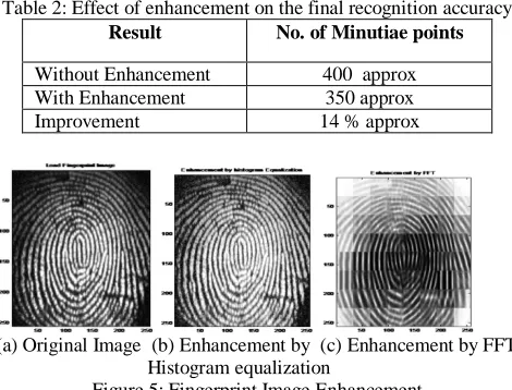
The result before and after enhancement are as shown in the figure and table 2. and figure:5
Table 2: Effect of enhancement on the final recognition accuracy
Result No. of Minutiae points
Without Enhancement 400 approx With Enhancement 350 approx Improvement 14 % approx
(a) Original Image (b) Enhancement by (c) Enhancement by FFT Histogram equalization
Figure 5: Fingerprint Image Enhancement
4.1.2 Binarization, Orientation Estimation and Region of Interest: The next step is adaptive binarization of image. In case of image binarization we basically binarize the image by extracting the lightness of the image that is we extract the brightness and density of the image as a feature amount from the image. Gabor filters were employed to enhance quality of image. Orientation estimation and ridge frequency images are requirements for implementing gabor filters. σx and σy
are taken 0.5 in Raymond Thai, but here σx = 0.7 and σy =
0.7 has been used.
(a) Adaptive Binarization (b) Orientation Field Estimation (c) Region of Interest
Figure 4.5: Binarization, Orientation & ROI
4.1.2.1 Thinning & Removing H Breaks and Spikes
After the fingerprint image is enhanced, it is then converted to binary form, and submitted to the thinning algorithm which reduces the ridge thickness to one pixel wide. Then H breaks and spikes are removed using morphological operation on thinned image. Results of thinned ridge map, removed H breaks and removed spikes are shown in figure 6.
(a) Thinned Ridge map (b) Remove H breaks (c) Remove spikes Figure 6: Thinned ridge map & Removed H Breaks and Spikes
4.2 Feature Extraction 4.2.1 Minutiae Extraction
Using the crossing number method, minutiae are extracted. For this a skeleton image or the thinned image has been used. Due to low quality of fingerprint, a lot of false and boundary minutiae were found. So post-processing steps are applied for better results and results are shown in figure 7.
(a) Minutiae (b) Removed Spurious minutiae Figure 7: All Extracted Minutiae & Real Minutiae
Minutiae extraction process results with too many false minutiae and these false minutiae are removed by removing H bridges and spikes. These steps are shown in figure 4.7. As we can see from Table 3 that removing spurious minutiae considerably reduced the number of false minutiae from minutiae extraction results. This process will improve our system accuracy because after removing spurious minutiae there will be only real minutiae to match.
Table 3: Average Number of Minutiae before and after post-processing Fingerprint Used Minutiae after
Extraction for each finger
After removing spurious minutiae for each finger
20 218 186
4.2.2 Minutiae marking:
After completion of fingerprint ridge thinning, minutiae marking is done by using 3 x3 pixel window. In case of minutia marking the concept of Crossing Number (CN) is mainly used [22][23].
4.2.2.1 Crossing-Number Concept:
value. A ridge pixel with a CN of one corresponds to a ridge ending, and a CN of three corresponds to a bifurcation. For each extracted minutiae point, the following information is recorded:
• x and y coordinates,
• orientation of the associated ridge segment, and • type of minutiae (ridge ending or bifurcation).
4.2.2.2 Basic Process:
The basic algorithm performed minutiae extraction using the skeleton image. The approach involves using a 3 x3 window to examine the local neighborhood of each ridge pixel in the image. A pixel is then classified as a ridge ending if it has only one neighboring ridge pixel in the window, and classified as a bifurcation if it has three neighboring ridge pixels. This approach have been shown in Table 4.
Table 4: Neighborhood pixels and their properties of minutiae points
Neighborhood pixels Property of the minutiae point
1 Ridge Ending
3 Ridge Bifurcation
2,4,5,6,7,8 False Minutiae
Figure 8 shows a 3 x 3 window if the central pixel is 1 and has exactly 3 one-value neighbors, then the central pixel is a ridge branch or bifurcation. i.e CN(p)=3 and if the central pixel is 1 and has only 1 one-value neighbor, then the central pixel is a ridge ending or termination. i.e CN(p)=1 for a pixel “p”.
Figure 8: Bifurcation & Bifurcation
4.3 Post Processing Stage:
For the post processing stage, it has two steps that are: i) Removal of false minutia
ii) Unify termination and bifurcation
After removing false minutiae, they will be stored in to database for the purpose of matching.
4.3.1 Removal of False Minutia:
To make the fingerprint recognition system consistent false minutiae have to be removed. Here first of all we have to calculate the inter ridge distance (D) which is the average distance between two neighboring ridges. By using the formula given by the equation 2.5 we can calculate the inter ridge distance (D) easily.
Inter ridge distance = 𝑠𝑢𝑚 𝑜𝑓 𝑎𝑙𝑙 𝑝𝑖𝑥𝑒𝑙𝑠 𝑤𝑖𝑡ℎ 𝑣𝑎𝑙𝑢𝑒 1
𝑟𝑜𝑤 𝑙𝑒𝑛𝑔𝑡ℎ Finally an averaged value over all rows gives D.
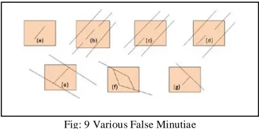
Seven types of false minutia are specified in following figure:
Fig: 9 Various False Minutiae
Figure 9 shows various types of false minutiae. In figure ‘a’ it is a only one short ridge. In the case of ‘b’ a third ridge is present in the middle of the two parts of the broken ridge. The two ridge broken points in the ‘c’ case have a short distance and also nearly the same orientation. In case of ‘d’ is same as the ‘c’ case with the exception that one part of the broken ridge is so short that another termination is generated. In case of ‘e’ a spike falsely connects two ridges. In figure ‘f’ has in the same ridge the two near bifurcations located. In case of ‘g’ it is a spike which piercing into a valley.
The following steps are taken into account for the removal of false minutia:
• If the value of d(termination, termination) is less than D & the two minutia are in the same ridge then remove both of them (case a). Here D is the average inter-ridge width.
• If the value of d(termination, termination) is equal to D & the their directions are coincident with a small angle variation & no any other termination is located between the two terminations then we have to remove both of them (case b, c, d)
• If the value of d(bifurcation, bifurcation) less than D & the two minutia are in the same ridge them remove both of them (case e, f)
• If the value of d(bifurcation, termination) is less than D & the 2 minutia are in the same ridge then remove both of them (case g).
Here d(X, Y) is the distance between the two minutia points.
4.3.2 Unify termination and bifurcation:
We know one type of minutia can be change to other type easily, coming in contact with the different types of data acquisition conditions. Each minutia is completely characterized by the following parameters at last:
1) x-coordinate 2) y-coordinate 3) Orientation. 4) Associated ridge
Actually a bifurcation can be broken down to three terminations each having their own x-y coordinates, orientation and an associated ridge.
The orientation for each termination (tx, ty) is estimated by using the following method.
i) First of all we have to track a ridge segment, whose starting point must be the termination and length is D. ii) Then sum up all the x-coordinates of points present in that particular ridge segment.
iii) After that to get sx we have to divide the above summation with D and sequentially we get sy using the same technique.
Now we can get the direction from the expression given by the equation 4:
tan-1�𝑠𝑦−𝑡𝑦 𝑠𝑥−𝑡𝑥�
(4)
5. Parameter variation of fingerprint: The variations are rotation, shift of fingerprint in vertical and horizontal plane of acquisition device. These variations can result in a significant number of spurious minutiae by which genuine minutiae may be ignored. That is why different variation of fingerprint has been saved in database as template to increase the accuracy of the system. Based on the objective, the data range that has been chosen for these parameters are: Angle = -30 to 30 deg
Shift in x axis = -5 to 5 pixels Shift in y axis = -5 to 5 pixels
These data has been chosen to introduce these distortions in fingerprint and then they will be stored into database. A test input fingerprint will be compared with these various types of stored templates and nearest among all will be displayed as a valid fingerprint.
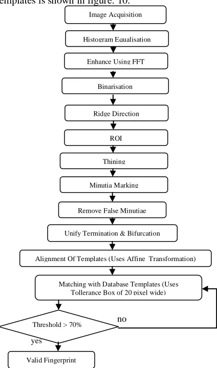
6. Matching Algorithm: The algorithm for matching templates is shown in figure: 10.
yes
no
yes
Figure 10: Test fingerprint matching Algorithm
If the threshold of query fingerprint is more than 70% then this fingerprint will be a valid fingerprint else it will be returned to matching stage to match again. Matching is performed using minutiae alignment and minutiae matching steps. First of all the minutiae are aligned to a new coordinate to know their position or location and then matching is performed with test fingerprint templates.
6.1 Minutiae alignment:
1) Let I1 & I2 be the two minutiae sets given by the equation 5 and 6:
I1 = { m1, m2, … . mM } where mi = ( xi , yi , θi ) (5) I2 = { m'1, m'2, … . m'M } where m'i = ( x'i , y'i , θ'i ) (6) The ridge associated with each minutia is represented as a series of x-coordinates (x1, x2…xn) of the points on the ridge. A point is sampled per ridge length L starting from the minutia point, where the L is the average inter-ridge length. And n is set to 10 unless the total ridge length is less than 10*L[34].
Equation 7 gives the similarity of correlating the two ridges and is derived from the following formula:
S = ∑ 𝑥𝑖𝑋𝑖 𝑚 𝑖=0
�∑𝑚𝑖=0𝑥𝑖2𝑋𝑖2 (7) At this stage (xi….xn) and (Xi….Xn) are the set of x-coordinates for the two minutia which we have chosen. And the least possible of ‘m’ is one of the value of n and N. We will tally the score and if the score is greater than 0.8, then jump to step 2, if not then continue to match the next ridges pair.
2. Here we have transformed each set according to its own reference minutia and then matched in a unified x-y coordinate. This transformation is called as Affine transformation. An affine transformation is any transformation that preserves co linearity (i.e., all points lying on a line initially still lie on a line after transformation) and ratios of distances (e.g., the midpoint of a line segment remains the midpoint after transformation). In this sense, affine indicates a special class of projective transformations that do not move any objects from the affine space R3 to the plane at infinity or conversely.
We are taking M (x, y, θ) as reference minutia which is in I1. We have to translate and rotate all other minutiae (xi, yi, θi) for the finger prints we have taken into account with respect
to the M ( x, y, θ ) .
�
𝑥_𝑛𝑒𝑤 𝑦_𝑛𝑒𝑤
𝜃_𝑛𝑒𝑤�=(TM) ×� 𝑥𝑖 − 𝑥 𝑦𝑖 − 𝑦
𝜃𝑖 − 𝜃� (8)
& TM = �𝑐𝑜𝑠𝜃 −𝑠𝑖𝑛𝜃𝑠𝑖𝑛𝜃 𝑐𝑜𝑠𝜃 00
0 0 1� Where TM is a transformation matrix. The new coordinate system is originated at reference minutia M and the new x-axis is coincident with the direction of minutia M. Therefore we are getting transformed sets of minutiae I1 & I2 .
6.2 Match stage:
An elastic string (x,y,θ) match algorithm is used to find number of matched minutia pairs among I1’ & I2’. According to the elastic string match algorithm minutia mi in I1’ and a Image Acquisition
Histogram Equalisation
Enhance Using FFT
Binarisation
Ridge Direction
ROI
Thining
Minutia Marking
Remove False Minutiae
Unify Termination & Bifurcation
Alignment Of Templates (Uses Affine Transformation)
Matching with Database Templates (Uses Tollerance Box of 20 pixel wide)
Threshold > 70%
Valid Fingerprint
minutia mj in I2’ are considered "matching," if the spatial distance (sd) between them is smaller than a given tolerance r0 and the direction difference (dd) between them is smaller than an angular tolerance θ0. This spatial distance (sd) and direction difference (dd) is calculated by the formula given by the equation 9 and equation 10 respectively[35].
sd = �(𝑥𝑖 − 𝑥𝑗)2+ (𝑦𝑖 − 𝑦𝑗)2 ≤ r0 (9) dd = (|θi- θj|, 360 - |θi- θj|) ≤ θ0 (10) Let mm(mi,mj) be an indicator function which is given by the equation 11, that returns 1 in the case where the minutiae mi and mj match according to above equations.
mm(mi,mj)= 1, sd(mi,mj) ≤ r0 and dd(mi,mj) ≤ θ0 (11) 0, otherwise
Now the total number of matched minutiae pair given by the equation 12,
num (matched minutiae) = Σmm (mi,mj) (12)
Generally the two identical minutiae are not exactly same due to the slight deformations and also in exact quantization. The algorithm for matching for the aligned minutia patterns should be elastic. The minutia matching elastic is done by keeping a bounding box around each of the template minutia. If the minutia which is to be matched is within that rectangle box and the direction discrepancy between them is so small, then the two minutiae are taken as a pair of matched minutia. Each of the minutiae in that template image either has one corresponding minutia or has no matched.
Figure 11: Approach of matching technique
The figure 11 shows the matching technique used in our approach. The tolerance box is taken as 10x10 pixel. First block shows the paired minutia in which both minutiae comes into the tolerance box and angle of both the minutiae are same. Third box shows the paired minutia but it has a different angle which can reduce the matching percentage. Forth box shows the unmatched minutiae in which one minutia is inside the box but second one is outside the box that shows these are minutiae of different fingerprint.
The final match ratio for two fingerprints is given by the equation 13.
Match Score = 𝑛𝑢𝑚𝑏𝑒𝑟 𝑜𝑓 𝑡𝑜𝑡𝑎𝑙 𝑚𝑎𝑡𝑐ℎ𝑒𝑑 𝑚𝑖𝑛𝑢𝑖𝑎𝑒 𝑝𝑎𝑖𝑟
𝑛𝑢𝑚𝑏𝑒𝑟 𝑜𝑓 𝑚𝑖𝑛𝑢𝑡𝑖𝑎𝑒 𝑜𝑓 𝑡ℎ𝑒 𝑡𝑒𝑚𝑝𝑙𝑎𝑡𝑒 𝑓𝑖𝑛𝑔𝑒𝑟𝑝𝑟𝑖𝑛𝑡 (13) If the match score is greater than a threshold value which is pre-specified, then the two fingerprints taken are from the same finger.
7. Results: 7.1 Database:
Here self made database of 20(27 templates for each finger) fingerprints has been made. Each template has the information about each minutiae coordinate and ridge angle. Fingerprint images are numbered from ‘a’ to ‘t’ followed by an another name for template from A_1 to A_27 which mean that the image fingerprint has1 to 27 templates of a certain finger (Fig.12).
Figure12: Sample of fingerprint in Database
7.2 Data range and plots:
The estimation of the data range is based on the experiments of the 20 fingerprints in the database. Based on the objective, the data range that we choose for these parameters are: Angle = -30 to 30 (total 5 samples)
Shift in x axis = -5 to 5 (total 11 samples) Shift in y axis = -5 to 5 (total 11 samples)
The plots in figure4.3 shows matching of fingerprint when ‘a’ image is given as input fingerprint and there is maximum matching percent shown with the previously stored fingerprint ‘a’. Similarly next plot shows that when ‘b’ image is given as input fingerprint and there is maximum matching percent shown with the previously stored fingerprint.
(a) (a)
(b) (b)
(c) (c)
Figure 13: Plot for matching of fingerprint ‘a’ and ‘b’ with itself for different parameters (a) Rotation (b) Shift in x axis (c) Shift in y axis
7.3 Matching: There are 20 fingerprints stored in the database which has been compared to input reference image.
1 2 3 4 5 6 7 8 9 10 0 10 20 30 40 50 60 70 80 90 100 Folder number(1-10) M at c hi ng P er c ent age( % )
Fingerprint a Angle plot
1 2 3 4 5 6 7 8 9 10 0 10 20 30 40 50 60 70 80 90 100 Folder number(1-10) M at c hi ng P er c ent age( % )
Fingerprint b Angle plot
1 2 3 4 5 6 7 8 9 10 0 10 20 30 40 50 60 70 80 90 100 Folder number(1-10) M at c hi ng P er c ent age( % )
Fingerprint a Shift in x axis plot
1 2 3 4 5 6 7 8 9 10 0 10 20 30 40 50 60 70 80 90 100 Folder number(1-10) M at c hi ng P er c ent age( % )
Fingerprint b Shift in x axis plot
1 2 3 4 5 6 7 8 9 10 0 10 20 30 40 50 60 70 80 90 100 Folder number(1-10) M at c hi ng P er c ent age( % )
Fingerprint a Shift in y direction plot
1 2 3 4 5 6 7 8 9 10 0 10 20 30 40 50 60 70 80 90 100 Folder number(1-10) M at c hi ng P er c ent age( % )
The overall threshold is chosen with the help of data given below in the table. From the table it is seen that the threshold is 70% above which all valid fingerprint will be accepted. Below this threshold false acceptance will occur. This table shows the matching percentage of a fingerprint image with only 5 images from the database. First column shows the matching percentage of finger ‘a’ with all the fingers in the database. When this image is matches with itself, it gives 100 % matching and when it matches with other fingers in the database the matching percentage falls below 70 %. This shows that when a finger is being matched with different fingerprint the maximum matching percentage does not exceed from 70 %. Similarly for all images the maximum matching percentage with different finger is not exceeding the value of 70 %. By this observation we have decided to choose the value of threshold as 70 %.
Table 5: Matching percentage (%) of a fingerprint with all images in database
Matching percentage (%) of a fingerprint
with all images in database
F in g er p ri n t F in g er a F in g er b F in g er c F in g er d F in g er e T h re sho ld (%)
Finger a 100 40 60 55 50
70 Finger b 60 100 55 60 45
Finger c 55 40 100 55 55
Finger d 60 55 45 100 65
Finger e 45 45 50 45 100
Table 6: shows a matching percentage of a finger when it is being matched by three different variations of fingerprint. These variations of finger are rotation, shift in x axis & shift in y axis.
Table 6: Showing matching percentage with variation
F in g er p ri n t im age F in g er a F in g er b F in g er c P a ram e ter v a ria tio n R o ta tio n S h if t in x a x is S h if t in y a x is R o ta tio n S h if t in x a x is S h if t in y a x is R o ta tio n S h if t in x a x is S h if t in y a x is
Finger a 100 100 100 43 36 36 38 41 38
Finger b 60 52 60 100 100 100 54 49 49
Finger c 52 57 57 45 45 41 100 100 100
7.4 Performance Evaluation Index: There are two types of performance evaluation indexes to determine the performance of a fingerprint recognition system such as:-
7.4.1 False Rejection Rate (FRR): Sometimes the biometric security system may incorrectly reject an access
attempt by an authorized user. To measure these types of incidents FAR is basically used. A system’s FRR basically states the ratio between the number of false rejections and the number of identification attempts.
% FRR= (FR/N)*100 FR=number of incidents of false rejections
N= number of samples
7.4.2 False Acceptance Rate (FAR): Sometimes the biometric security system may incorrectly accept an access attempt of an unauthorized user. To measure these types of incidents FAR is basically used. A system’s FAR basically states the ratio between the number of false acceptances and the number of identification attempts.
% FAR= (FA/N)*100 FA= number of incidents of false acceptance N=total number of samples
As threshold value increases, false acceptance rate and false reject rate decreases. These observations have been shown in Table 7 given below. The test shows that the threshold value should be atleast 70% to get better accuracy of the system. At this value the false acceptance can be easily caught because the acceptance rate is approaching to zero.
Table 4.7 Performance evaluation index
Our Approach Existing Method
T h re sho ld V a lu e ( I n % ) F a ls e A cc ep ta n ce R a te ( In % ) F a ls e R ej ec t R a te ( In % ) R un T im e (I n Se c) A cc u ra cy ( In % ) (A t t h re sh o ld of 7 0 %) F a ls e A cc ep ta n ce R a te (I n % ) F a ls e R ej ec t R a te (I n % ) R un T im e (I n Se c) A cc u ra cy ( In % ) (A t t h re sh o ld of 7 0 %)
50 10 15
14 100
7 15
35 80
55 5 10 7 8
60 5 5 6 5
70 0 0 0 3
75 0 0 0 2
FAR= Percentage of acceptance of invalid image FRR= Percentage of rejection valid image
Table 7 shows that our approach for increasing accuracy is much better than the existing algorithm because the false acceptance and false rejection rates are approximately zero above threshold but existing algorithm has some false acceptance and false rejection rate as well as run time of our system is approximately half of the existing algorithm. Our feature extraction algorithm takes on an average 10 seconds for 288x384 size image for registration. A fingerprint is said to be matched if the correct match appears
in the shortlist obtained by the matching algorithm. We have achieved 100 % accuracy with this method with 70% of threshold.
A random sample of 20 fingerprints was chosen to test the matching algorithm on the database. With the reject rate of 5%, we achieved 95% accuracy on this database whereas existing method has 15% reject rate with 80% of accuracy. Although the matching step takes about four second per match, the total time taken to match against a large database can be very high since the registration has to be done first for each record in the database. The run time of the recognition system has been reduced by not comparing test fingerprint with whole database when matching percentage becomes greater than a set threshold. This saves time of system and show result quickly.
8. Conclusion:
The theory behind the fingerprint verification based on minutiae matching, was in detail studied. With obtained knowledge the complete system has been designed and implemented in MATLAB. The performance of the developed system was evaluated on database with 20 fingerprints from different people. The test showed that the system is fully capable of distinguishing the related fingerprints apart from the non-related fingerprints. The system has proved to be robust towards rotation, shift of finger in up/down and left/right position on acquisition device.
In this thesis work, minutiae based matching technique has been proposed to increase efficiency of the fingerprint recognition systems. In the proposed technique, fingerprint image enhancement is used by histogram equalization, image binarization is used, and image segmentation is used by the morphological operations. Minutiae extraction processes have two steps which are image thinning and minutiae marking have been used. Minutiae marking have been done by the crossing number concept. Extracted minutiae are stored into database and later, these minutiae are compared to get the maximum matching percentage. On theoretical basis, it has been shown that the proposed algorithm is more efficient than the existing algorithm. This thesis focuses on three principal challenges in fingerprint recognition: robust feature extraction from low-quality fingerprints, matching elastically deformed fingerprints, and efficient search of fingerprints in a database. Research into these topics has yielded improvements for most of these challenges, resulting in a system that provides increased fingerprint recognition performance.
An efficient method for minutiae extraction has been developed that roughly follows the traditional approach, involving a number of image processing steps such as enhancement, thresholding, and thinning. A combination of good noise suppression performance and low computational complexity is achieved by an enhancement algorithm that uses separable complex-valued Gabor filters, while efficient minutiae extraction is obtained by crossing number concept. To compare the minutiae sets of two fingerprints, an elastic minutiae matching algorithm has been proposed. The elastic
minutiae matching algorithm is able to determine the correspondence between elastically deformed fingerprints, where the traditional rigid matching algorithms fail.
REFERENCES:
[1] Le Hoang Thai and Ha Nhat Tam “Fingerprint recognition using
standardized fingerprint model” IJCSI International Journal of Computer
Science Issues, Vol. 7, Issue 3, No 7, May 2010.
[2] Dario Maio and Davide maltoni “Direct Gray Scale Minutiae Detection
in Fingerprints”, IEEE transactions on pattern Analysis and Machine
Intelligence, Vol.19,no. 1, pp. 27-40,1997.
[3] Ton van der Putte and jeroen Keuning “Biometrical Fingerprint
Recognition”, Fourth Working Conference on Smart Card Research and
advanced application, pp 289-303,2000.
[4] Zsolt Milko, Kova CS Vajna “ A Fingerprint Verification System Based
on Triangular Matching and Dynamic Time Warping”, IEEE transaction on
Pattern Analysis and Machine Intelligence, Vol.22, no.11,pp. 1266-1276,
2000.
[5] Jain, A., Hong, L., Pankanti, S., and Bolle, R. An Identity
Authentication System Using Fingerprints. In Proceedings of the IEEE
(September 1997), vol. 85, pp. 1365–1388.
[6] Milene Arantes, Alesssandro Noriaki Ide “A System For Fingerprint
Minutiae Classification and Recognition”, Proceedings of the IEEE
International Conference on Neural Information Processing. Vol.5,pp.
2474-2478,2002.
[7] Sen Wang Wei Wei Zhang Yang Sheng Wang “ Fingerprint
Classification by Directional Fields”, Proceedings of the Forth IEEE
International Conference on Multimodal Interfaces, pp.234-239, 2002.
[8] Naresh Kumar, Parag Verma “Fingerprint Image Enhancement And
Minutia Matching”, International Journal of Engineering Sciences &
Emerging Technologies, June 2012,
[9] Dongjae Lee, Kyoungtaek Choi, and Jaihie Kim “A Robust Fingerprint
Matching Algorithm Using Local Alignment”, Yonsei Univ., Seoul, Korea.
[10] Abinandhan Chandrasekaran & Dr.Bhavani Thuraisingham
“Fingerprint Matching Algorithm Based on Tree Comparison using Ratios
of Relational Distances” , Assistant IEEE Fellow, AAAS Fellow, Data and
Applications Security Laboratory, Department of Computer Science,
University of Texas at Dallas.
[11] Sen Wang and Yangsheng Wang “ Fingerprint Enhancement in the
Singular Point Area”, IEEE Signal Processing Letters, Vol. 11, no. 1, pp.
16-19, 2004.
[12] D. Maltoni, D. Maio, and A. Jain, S. Prabhakar, “Minutiae based
Methods” (extract) from Handbook of Fingerprint Recognition”, Springer,
New York, pp. 141-144, 2003.
[13] L. Hong, "Automatic Personal Identification Using Fingerprints",
Ph.D. Thesis, 1998
[14] K. Nallaperumall, A. L. Fred and S. Padmapriya, “A Novel for
Fingerprint Feature Extraction Using Fixed Size Templates”, IEEE 2005
Conference, pp. 371-374, 2005
[15] Sharat Chikkerur, Venu Govindraju, Sharath Pankanti, Rund Bolle and
Nalini Ratha “ Novel Approaches for Minutiae Verification in Fingerpriint
Images”, Proceeding of the Seventh IEEE Workshop on Applications of
Computer Vision, pp. 456-462, 2005.
[16] Wikipedia link - http://en.wikipedia.org/wiki/Fingerprint_recognition
[17] P. Komarinski, P. T. Higgins, and K. M. Higgins, K. Fox Lisa ,
“Automated Fingerprint Identification Systems (AFIS)”, Elsevier Academic
Press, pp. 1-118, 2005.
[18] Lin Hong, Student Member, IEEE, Yifei Wan, and Anil Jain,
“Fingerprint Image Enhancement: Algorithm and Performance Evaluation”
IEEE TRANSACTIONS ON PATTERN ANALYSIS AND MACHINE
INTELLIGENCE, VOL. 20, pp. 777-787, 1998 .
[19] E. Hastings, “A Survey of Thinning Methodologies”, Pattern analysis
and Machine Intelligence, IEEE Transactions, vol. 4, Issue 9, pp. 869-885,
1992.
[20] L. Lam, S. W. Lee, and C. Y. Suen, “Thinning Methodologies-A
Comprehensive Survey”, IEEE Transactions on Pattern Analysis and
Machine Intelligence, vol. 14, no. 9, 1992.
[21] K. Nallaperumall, A. L. Fred, and S. Padmapriya, “A Novel Technique
for Fingerprint Feature Extraction Using Fixed Size Templates”, IEEE 2005
Conference, pp. 371-374, 2005.
[22] P. I. Rockett. An Improved Rotation Invariant Thinning Algorithm.
Pattern Analysis and Machine Intelligence, IEEE Transactions on,
27(10):1671–1674, 2005.
[23] A. Ross, A. K. Jain, and J. Reisman. “A Hybrid Fingerprint Matcher”.
Pattern Recognition, 36(7):1661–1673, 2003.
[24] B. G. Sherlock, D. M. Monro, and K. Millard. Fingerprint enhancement
by directional fourier filtering. Vision, Image and Signal Processing, IEEE
Proceedings, 141(2):87–94, 1994. 1350-245X.
[25] S. Wang and Y. Wang. Fingerprint enhancement in the singular point
area. IEEE Signal Processing Letters, 11(1):16–19, January 2004.
[26] A. J. Willis and L. Myers. A cost-effective fingerprint recognition
system for use with low-quality prints and damaged fingertips. Pattern
Recognition, 34(2):255–270, 2001.
[27] C. Wu, Z. Shi, and V. Govindaraju. Fingerprint image enhancement
method using directional median filter. In Biometric Technology for Human
Identification, SPIE, volume 5404, pages 66–75, 2004.
[28] C. Wu, S. Tulyakov, and V. Govindaraju. Image quality measures for
fingerprint image enhancement. In International Workshop on Multimedia
Content Representation, Classification and Security(MRCS), volume LNCS
4105, pages 215–222, 2006.
[29] Q. Xiao and H. Raafat. Fingerprint image postprocessing: A combined
statistical and structural approach. Pattern Recognition, 24(10):985–992,
1991.
[30] J. Xudong and Y. Wei-Yun. “Fingerprint minutiae matching based on
the local and global structures”. In Proc. of International Conference on
Pattern Recognition (ICPR), volume 2, pages 1038–1041 vol.2, 2000.