Mitigation of Neutral Current in a Three
Phase System using Electric Springs
P. Asha
1, Ancy Sara Varghese
2PG Student, Dept. of EEE, Saintgits College of Engineering, Kottayam, Kerala, India1
Assistant Professor, Dept. of EEE, Saintgits College of Engineering, Kottayam, Kerala, India2
ABSTRACT: Three-Phase four-wire distribution systems are widely used for distributing power to many residential and commercial buildings. The increased use of non-linear and unbalanced loads in these systems may result in excessive neutral currents. This may damage the neutral conductor and distribution transformer while affecting the safety of the consumers and also causes several other power quality problems in the system. The proposed strategy employs a new three phase electric spring circuit for reducing neutral current in the system. MATLAB/SIMULINK platform is used for simulation. The application of the proposed method has been investigated for different load conditions and the results are presented.
KEYWORDS:Electric Spring (ES), Neutral Current, Particle Swarm Optimization (PSO), Smart load.
I.INTRODUCTION
In manufacturing plants, commercial and residential buildings, power is distributed through three-phase, four-wire (3P4W) systems. In these systems, single phase supply to loads is provided by one of the phase conductors and neutral wire. To balance the load on each of the phases, the loads are evenly distributed. Due to the unbalanced nature of the loads, a net current flowing through the neutral conductor.With linear loads, the neutral current is only due to imbalance between the phases.
The typical loads in a three-phase four-wire distribution system may be computer loads, lighting ballasts, small rating adjustable speeds drives (ASD) in air conditioners, fans, refrigerators and other domestic appliances etc. These non linear loads produces third harmonic components in the system. The inductive ballasts as well as electronic ballasts in fluorescent lighting also contribute to third harmonic currents. The third harmonic components in phase currents do not cancel each other even under balanced condition and are added up in the neutral line. Therefore, the total neutral current is contributed by the fundamental and harmonic components of the unbalanced load currents and thus results in the overload of neutral conductor in the three phase four wire distribution systems.
The excessive neutral current increases line losses, deteriorates system voltage profiles, overloads system phases, results in mal-functioning of protective relays, causes saturation problem in the distribution power transformers, increases communication interference, deteriorates power quality, system security and reliability of the electric supply, etc. The voltage difference between neutral and ground causes malfunction of sensitive electronic equipments. Neutral current and neutral voltage in three-phase four-wire distribution system is a serious concern in power system as they deteriorate the overall performance of distribution systems [1].
There are various approaches that deals with mitigation of neutral current. Conventional passive and active power filters have been employed to solve the problems of harmonic currents and neutral-line current in three-phase four-wire distribution power systems [2]-[4]. The performance of passive filter is often significantly affected by the system impedance. Furthermore, the disadvantages including large volume, parallel resonance, and series resonance may further offset the benefits of this method. The capacity and manufacturing cost of the power converter used in active filter is very high, thus limiting wide application of active power filters.
nonideal magnetic coupling does not allow perfect filter performance. The zig-zag transformer is connected to the load in parallel, has been employed to attenuate the neutral-line current due to the advantages of low cost, high reliability and simplified circuit connection [6]. However, application of this method may result in the neutral voltage variation or raising the neutral voltage of the load side.
The electric spring is a new demand side management technology [7] . It can provide electric active suspension functions for voltage and frequency stability in a distributed manner for future smart grid [8]. The subtle change from output voltage control to input voltage control of a reactive power controller makes the electric spring suitable for future smart grid applications. For the compensation of neutral current, a new three-phase ES topology is proposed and its operating principle is explained. Its ability to enhance the power system stability and its use for reducing neutral current in a three-phase power system is demonstrated in a simulation study. The effectiveness of the proposed system under different load conditions are also verified in the simulation study.
II.PRINCIPLE OF THREE PHASE ELECTRIC SPRING
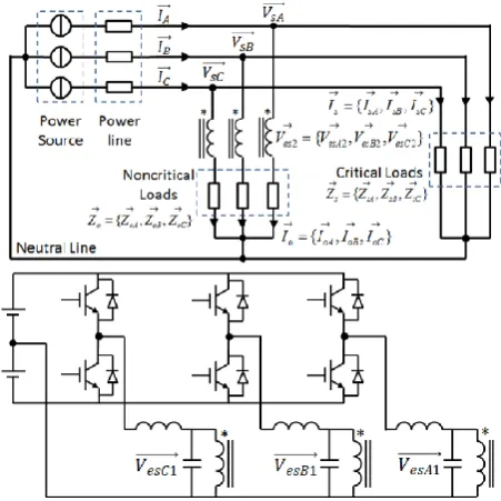
A three-phase Electric Spring takes the form of a three-phase inverter with a small battery storage on its DC link and an LC filter in the output of each inverter leg. The inverter output of each phase is connected to the primary side of an isolation transformer. The secondary sides of three isolation transformers are connected in series with three noncritical loads in star connection with the neutral line connected to the neutral point of three phase power source. The series connection of the electric spring and the non critical loads is collectively termed as smart load. Critical loads in star connection are connected in parallel with the smart load. The neutral point of critical load is also connected to the neutral point of power source.
Fig. 1 Circuit diagram and placement of a three phase Electric Spring
In this system, it is assumed that the critical loads are unbalanced among the three phases and the non-critical loads are balanced loads. The sum of power consumptions in the non-critical loads and critical loads represents the total power consumption. Without compensation, the line currents are unbalanced due to the asymmetric load impedance of the critical loads and are given by
I
A=
1
𝑍
𝑠𝐴+
1
𝑍
𝑜𝐴𝑉
𝑠𝐴− (
1
𝑍
𝑜𝐴) 𝑉
𝑒𝑠𝐴IB =
1 ZsB +
1
ZoB VsB− ( 1
ZoB ) VesB(1)
IC=
1
𝑍𝑠𝐶
+ 1
𝑍𝑜𝐶
𝑉𝑠𝐶− (
1
𝑍𝑜𝐶
) 𝑉𝑒𝑠𝐶
The neutral current is the sum of three line currents and is given as
I
neutral=
1
𝑍𝑠𝐴
+
1
𝑍𝑜𝐴
𝑉
𝑠𝐴−
1
𝑍𝑜𝐴
𝑉
𝑒𝑠𝐴+
1
𝑍𝑠𝐵
+
1
𝑍𝑜𝐵
𝑉
𝑠𝐵−
1
𝑍𝑜𝐵
𝑉
𝑒𝑠𝐵+
1
𝑍𝑠𝐶
+
1
𝑍𝑜𝐶
𝑉
𝑠𝐶−
(
1𝑍𝑜𝐶
) 𝑉
𝑒𝑠𝐶(2)
ES voltage can be controlled actively to alter the line currents both in amplitude and phase within its operating limits, in response to the changing states of the critical loads. The limitations of the ES, is mathematically expressed as
0 ≤ 𝑉
𝑒𝑠𝐴, 𝑉
𝑒𝑠𝐵, 𝑉
𝑒𝑠𝐶≤ 𝑉
𝑑𝑐0
0≤ 𝜃
𝑉𝑒𝑠𝐴, 𝜃
𝑉𝑒𝑠𝐵 ,𝜃
𝑉𝑒𝑠𝐶≤ 360
0 (3)III. THE IMPLEMENTATION AND CONTROL OF THREE-PHASE ELECTRIC SPRING FOR THE REDUCTION NEUTRAL CURRENT
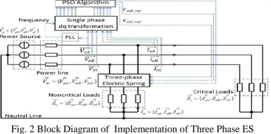
The power inverter needs to operate in a special manner for neutral current mitigation. Besides the power inverter, a feasible three-phase ES system includes a PLL (Phase Locked Loop) block, single-phase d-q transformation block and a Particle Swarm Optimization (PSO) based controller.In order to acquire accurate feedback, all variables in three-phase ES system should be synchronized under a fixed fundamental frequency. This is realized by the installation of a PLL block which generates the fundamental system frequency and provides a reference vector with 0° phase angle. The line voltage VsAis used as the reference vector. The single phase d-q transformation block decouples each current and voltage signal independently into d and q components. With the inclusion of PLL block, the decoupled voltages and currents are combined together into one d-q frame rotating at fundamental frequency of 50 Hz.
Fig. 2 Block Diagram of Implementation of Three Phase ES
velocity. Global best solution is obtained by all particles. Here the objective function is to minimize the neutral current and is given by equation (2).
Fig. 3 Particle Swarm Optimization based Algorithm
IV. SIMULATION RESULTS AND DISCUSSION
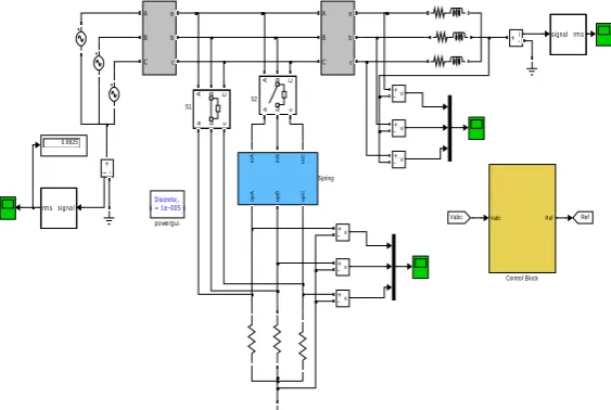
Fig. 4 shows the simulation model for the implementation of three phase Electric Spring for the reduction of neutral current in a distribution system. The simulations are done in Matlab/Simulink platform. The grid source is represented by three phase AC source. The non critical loads are purely resistive or heating loads, and are balanced loads. The critical loads are resistive cum inductive loads and are unbalanced loads. Two switches S1 and S2 are used. Both the switches have a transition time of 0.2 seconds. i.e, switch S1 is initially closed and S2 is initially open. Therefore, the non critical loads are directly connected to the grid up to 0.2 seconds. At 0.2 seconds, switch S1 is open and S2 is closed. At that time, the non critical loads are connected to the grid through the three phase electric spring. The critical loads are directly connected to the grid.
Fig. 4 Simulation Model for the Reduction of Neutral Current
i) System Specification
Table 1 shows the system parameter specification
Table 1: System Parameters
Grid Source Voltage 415 V, Three phase
AC
Frequency 50 Hz
S2 S1
Discrete, Ts = 1e-005 s.
powergui
v + -v + -v +
-v + -v + -v +
-A B C
a b c
A B C
a b c
A B C
a b c
A B C
a b c
opA opB opC inA inB inC
Spring
signal rms
signal rms
Ref Vabc
0.8825
i
+
-i +
-Vabc Ref
ii) Different Loading conditions
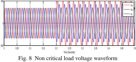
The performance of the system is observed by switching the Electric Spring at 0.2 seconds. From Figure 3, it is observed that the neutral current is reduced from 566.4 A to 0.8825 A with the introduction of compensation voltage VeS. Fig. 7 shows the voltage across the critical loads. It can be seen that, the constant power supply to the critical loads can be maintained. Figure 6 shows the voltage across the non critical loads. It can be seen that, the non critical load power consumptions are not identical. i.e, the reduction of neutral current is possible by the Electric Spring in transferring power imbalance to the non critical loads.
a)
Case 1
Table 2 shows the simulation results for the first loading condition.
Table 2: Case 1 loading Condition
Parameter PhaseA PhaseB PhaseC Supply side
neutral current (A) Non
Critical load(Ω)
0.275 0.275 0.275
ES off
ES 0n
Critical load (Ω)
0.075+ 0.425j
0.157+ 0.298j
0.171+ 0.171j
566.4 0.88
Fig. 5 shows the supply side neutral current waveform when an Electric Spring is connected at 0.2 seconds. It is shown that the neutral current is reduced from 566.4 A to 0.8825 A at 0.2 seconds.
Fig. 5 Supply side Neutral current waveform
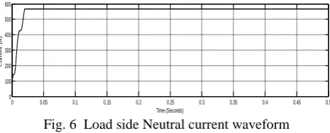
Fig. 6 shows the load side neutral current waveform. The load side neutral current waveform remains the same even when an ES is connected to the system.
Fig. 6 Load side Neutral current waveform
Fig. 7 shows the voltage across the critical loads. It is clear that, the voltage drop across the critical loads maintains throughout the period.
0 0.05 0.1 0.15 0.2 0.25 0.3 0.35 0.4 0.45 0.5 0
100 200 300 400 500 600
Time(Seconds)
C
u
r
r
e
n
t
(
A
)
0 0.05 0.1 0.15 0.2 0.25 0.3 0.35 0.4 0.45 0.5 0
100 200 300 400 500 600
Time (Seconds)
C
u
r
r
e
n
t
(
A
Fig. 7 Critical load voltage waveform
From Fig. 8, it is shown that the voltage across the non critical loads varies according to the Electric Spring voltage.
Fig. 8 Non critical load voltage waveform
Fig. 9 shows the voltage developed across the Three phase Electric Spring in order to acquire neutral current compensation.
Fig. 9 Three phase Electric Spring voltage
b)
Case 2
Table 3 shows the simulation results for the second loading condition.
Table 3: Case 2 Loading Condition
Parameter PhaseA PhaseB PhaseC Supply side
neutral current (A)
Non Critical load(Ω)
0.5 0.5 0.5
ES off
ES 0n
Critical load (Ω)
0.5+ 0.5j
0.2+ 0.3j
0.1+ 0.8j
213.5 0.339
Fig. 10 shows the supply side neutral current waveform when an Electric Spring is connected at 0.2 seconds. It is shown that the neutral current is reduced from 213.5 A to 0.339 A at 0.2 seconds.
0 0.05 0.1 0.15 0.2 0.25 0.3 0.35 0.4 0.45 0.5 -500
0 500
Time (Seconds)
V
o
l
t
a
g
e
(
V
)
Va Vb Vc
0 0.05 0.1 0.15 0.2 0.25 0.3 0.35 0.4 0.45 0.5 -500
0 500
Time (Seconds)
V
o
lt
a
g
e
(
V
)
Va Vb Vc
0 0.05 0.1 0.15 0.2 0.25 0.3 0.35 0.4 0.45 0.5
-1000 0 1000
Time (Seconds)
V
o
l
t
a
g
e
(
V
) Va
Fig. 10 Supply side Neutral current waveform
c)
Case 3
Table 4 shows the simulation results for the next loading condition.
Table 4: Case 3 Loading Condition
Parameter PhaseA PhaseB PhaseC Supply side
neutral current (A)
Non Critical load(Ω)
1 1 1
ES off
ES 0n
Critical load (Ω)
2+0.5j 1+0.2j 4+0.1j 168.1 0.265
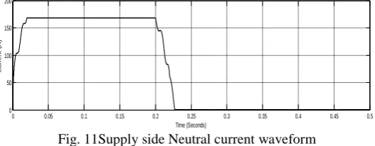
Fig. 11 shows the supply side neutral current waveform when an Electric Spring is connected at 0.2 seconds. It is shown that the neutral current is reduced from 168.1A to 0.265 A at 0.2 seconds.
Fig. 11Supply side Neutral current waveform
From Figures 10 and 11,it is observed that the source side neutral current is greatly reduced under different load conditions. The introduction of compensation voltage (three phase Electric Spring voltage), can actively change the power consumption of non- critical loads without affecting the power consumption of critical loads. In other words, the reduction of neutral current of the three phase system is made possible by the Electric Spring by changing the power consumption of non-critical loads.
VI.CONCLUSION
A new three phase Electric Spring circuit is introduced in to a three phase distribution system for reducing neutral current. The Particle Swarm Optimization (PSO) algorithm based controller is used for generating the control signals of Electric Spring. The simulation is done in a Matlab/Simulink platform. The simulation results shows that the Electric Spring is effective in reducing neutral current under different load conditions.
0 0.05 0.1 0.15 0.2 0.25 0.3 0.35 0.4 0.45 0.5 0
50 100 150 200 250
Time (Seconds)
C
u
r
r
e
n
t
(
A
)
0 0.05 0.1 0.15 0.2 0.25 0.3 0.35 0.4 0.45 0.5 0
50 100 150 200
Time (Seconds)
C
u
r
r
e
n
t
(
A
REFERENCES
[1] A. von Jouanne and B. Banerjee, “Assessment of voltage unbalance,” IEEE Trans. Power Delivery, vol. 16, no. 4, pp. 782–790, Oct. 2001. [2] F. Z. Peng, H. Akagi, and A. Nabae,“ A new approach to harmonic compensation in power systems-A combined system of shunt passive and
series active filters,” IEEE Trans. Ind. Applicat., vol. 26, pp. 983-990,Nov./Dec. 1990.
[3] V. B. Bhavaraju and P. N. Enjeti, „„Analysis and design of an active power filter for balancing unbalanced loads,‟‟ IEEE Trans. Power Electron.,vol. 8, no. 4, pp. 640--647, Oct. 1993.
[4] W. C. Lee, T. K. Lee, and D. S. Hyun, “A three-phase parallel active power filter operation with PCC voltage compensation with consideration for an unbalanced laod,” IEEE Trans. on Power Electron., vol. 17, no. 5, pp. 807–814, Sep. 2002.
[5] R. Apolonio, J. C. de Oliveira,and A. B. de Vasconcellos, “Three-Phase Electromagnetic Filter for Zero-Sequence Harmonics”, In Proc. of 11th International Conference on Harmonics and Quality of Power, 12-15 Sept. 2004, pp 613.
[6] S. Choi, and M. Jang, “Analysis and Control of a Single-Phase-Inverter Zigzag- Transformer Hybrid Neutral-Current Suppressor in Three-Phase Four-Wire Systems”, IEEE Transactions On Industrial Electronics, Vol. 54, No. 4,pp 2201–2208, August 2007.
[7] S. Y. R. Hui, C. K. Lee, and F. F. Wu, “ Electric springs - a new smart grid technology,” IEEE Trans. on Smart Grid, vol. 3, no. 3, pp. 1552-1561, Sep. 2012.
[8] S. Y. R. Hui, C. K. Lee, and F. F. Wu, “ Mitigating Voltage and Frequency Fluctuation in Microgrids Using Electric Springs”, IEEE Trans. Power Del., vol. 24, no. 4, pp. 2344-2352, Oct. 2013.
[9] C.K. Lee, S.C. Tan , and F.F. Wu,“ Use of Hookes Law for Stabilizing Future Smart Grid The Electric Spring Concept”, IEEE Trans. Smart Grid, vol. 4, no. 3, pp. 15581566, Sep. 2013.
[10] Kennedy.J and Eberhart, R.C.,“ Particle Swarm Optimization”, Proceedings of the 1995 IEEE International conference on Neural Networks, Perth, Australia, IEEE Service Center, Piscataway, NJ, IV:1942–1948.
[11] J. Kennedy, The Particle Swarm: Social adaptation of knowledge, Proceedings of the IEEE International Conference on Evolutionary Computation, Indianapolis, USA, 1997, pp. 303-308.
BIOGRAPHY
Asha. P, received B.Tech degree in Electrical and Electronics Engineering under Mahatma Gandhi University in 2009. She is currently pursuing her M.Tech in Power SystemsatSaintgits College of Engineering, Kerala, India.