ISSN 2286-4822 www.euacademic.org
Impact Factor: 3.4546 (UIF)
DRJI Value: 5.9 (B+)
Recent Development in Operating System
SIKANDER SHAHZAD Department of Computer Science Balochistan Agriculture College, Quetta Pakistan MUHAMMAD ASLAM NIAZI Balochistan Agriculture College, Quetta Pakistan ASAD KHAN Balochistan Agriculture College, Quetta Pakistan
Abstract:
Operating system is a program that provides platform to other programs to run. There are several operating systems such as multiprogramming operating system, network operating system, and distributed operating system. Operating system is a very broad field to discuss recent development in operating system therefore, it can be divided into sub areas such as file system, memory management, process management, and communications management. This document presents current finding in above mentioned sub areas in order to discuss recent development in operating system.
Key words: operating system, file system, memory management,
process management, communications management
1. Introduction
There are different operating systems available in the market as follows:
1.1 Multiprogramming Operating System1
In multiprogramming operating system, user can run more than one program at a time. There are different types of Multiprogramming Operating System, some of them are discussed below:
1.1.1 Multitasking Operating System
In multitasking operating system, user can perform more than one computer task at time. This feature is supported by all major operating systems.
1.1.2 Multiuser Operating System
In multiuser operating system, multiple user can use the same computer at a time or at different time. Linux, Unix, Windows Operating Systems are some example of multitasking operating system.
1.1.3 Multiprocessing Operating System
In multiprocessing operating system, more than one computer processor can be utilized Linux, Unix, Windows Operating System are some example of multiprocessing operating system.2
1.1.4 Real Time Operating System
Real Time Operating System is designed to run applications with very precise timing and a high degree of reliability. These operating system are designed for real-time applications. Such as embedded systems, robots, scientific research equipment.
1.2 Network Operating System
A network operating system (NOS) is designed to support workstations, personal computers and other network devices that are connected on a local area network (LAN).
1.3 Distributed Operating System
A distributed operating system is a collection of independent, networked, communicating, and physically separate computers. Each individual holds a specific software subset of the global aggregate operating system.2
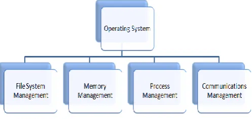
2. Recent Development in Operating System Research Operating system is a very broad field so it must be divided into sub areas in order to discuss recent development in operating system research. Figure 1 illustrates the sub areas of operating system.
Figure 1: Sub Areas of Operating System
2.1 File System
(New Technology File System) is a common file system in Windows Operating System which restores and manages the important data. It also supports a function of encrypting files, and so it can provide guaranteed security to the users [5].
We could not straightly examine in windows operating system if the vital data is deleted therefore, tapping and analyzing the data of NTFS file system is of great value.Object oriented idea can be used to design NTFS file parsing system which parses the most derived binary data that was saved to disk, getting the completely analysis of the normal files and the deleted files. After attaining all the data, display these in a tree structure on friendly interface to the user.
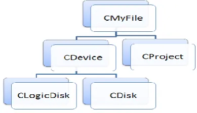
In object oriented idea, all files are viewed as an object which encapsulated each attribute of the object and different interface functions for the object. In the file list parsed disk, project, partition, directory and documents are inherited from CMyFile shown in figure 2.
Figure 2: Class structure of NTFS file system
According to the figure 2, CDevice and CProject classes are developed by CMyFile whereas CLogicDisk and CDisk are created by CDevice.
Figure 3: Resource structure of NTFS file system
In figure 3, CSource class shows the data source which includes hard disk data source and mirror image data source of this device. It constructs and gets each file object easily. CDeviceSource represents hard data source whereas CFileSource represents document data source.
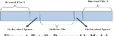
When the NTFS file is deleted, data area is not cleared at once. In fact system alters file status byte value from 01 to 00(deleted) in file record. Therefore there is always a chance to recover NTFS data but we can not see the deleted file at original position discussed before. If we write data into hard disk again, these group may be over write then the deleted file might not be recovered. Data area of deleted file can be defined as totally recoverable, partial recoverable and totally non-recoverable shown in figures 4, 5 and 6.
Figure 4: Totally Recoverable Model
Figure 6: Totally Non-Recoverable Model
Thus object-oriented method is used to design and analyze NTFS file system that inherits relationship and encapsulation of class to analyze different kinds of data sources. This method also implements normal file analysis and restores the deleted file. The result of analysis is displayed in a friendly interface.
2.2 Memory Management
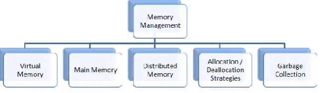
Memory management is responsible for managing the computer's primary memory. It keeps track of the status of each memory location, either allocated or free. Memory management is further divided into sub areas show in figure 7.
Figure 7: Sub areas of memory management
2.2.1 Virtual Memory
Virtual memory is used to compensate RAM (Random access memory) when computer lacks to run a program or operation. It is an alternate set of memory addresses which are used by the programs to store instruction and data.
volatile memory, Phase Change Memory (PCM) [2] is one of them. Such schemes must address the endurance of PCM which is the major challenge. There are two implementations to improve endurance of PCM in order to tradeoff time and space complexity. These are bucket based wear leveling and array based wear leveling [1].
Bucket based wear leveling
In bucket based wear leveling two bucket lists are used, free list and in-use list. Free list manages pages that are free whereas in-use list manages pages that are in use.
There are N buckets linked in a circular format under each bucket to apply different distances and ages of page. Once a page has been written R times, it would be moved to the next bucket with older pages. Buckets in free list and in use list communicate with each other. In order to find a free page for allocation without searching, it can always be obtained from one of the two base buckets. When both of them get empty, the bucket lists revolve so that the current base buckets become the buckets maintaining the oldest pages and the next buckets on the respective lists become the free and in-use base buckets.
Array based wear leveling
To determine if a page is new enough, two global counters m
count and b count are utilized. m count records the minimum write count. After the pivot pointer rotates back to the beginning of the array, a new round starts, and b count is set as
m count to fairly accurate the age of the latest pages when the new round begins.
Thus by integrating both techniques, bucket based wear leveling, and array based wear leveling into existing design of virtual memory management energy savings could be achieved.
2.3 Process Management
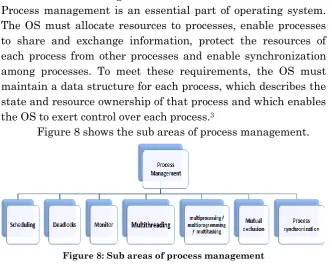
Process management is an essential part of operating system. The OS must allocate resources to processes, enable processes to share and exchange information, protect the resources of each process from other processes and enable synchronization among processes. To meet these requirements, the OS must maintain a data structure for each process, which describes the state and resource ownership of that process and which enables the OS to exert control over each process.3
Figure 8 shows the sub areas of process management.
Figure 8: Sub areas of process management
2.3.1 Deadlock
Deadlock is a situation where two or more processes are waiting for each other to complete before taking place that will never happen. Let’s say a computing action 'X' is waiting for
action 'Y' to complete, while action 'Y' can only execute when 'X' is completed. Such a state would be called a deadlock.
In operating systems, a deadlock situation is reached when computer resources required for completing a task are held by another task that is waiting to execute. The system thus goes into an indefinite loop resulting into a deadlock.
Deadlocks generally take place between threads in shared memory concurrent programming as a consequence of cyclic lock acquisition. When threads wait for a resource of each other to complete task, they go to state of deadlock. There are a number of techniques proposed to avoid deadlocks mainly programming language approaches that aim for static deadlock avoidance by employing type systems to avoid deadlocks [6]. Another method to prevent deadlock is dynamically avoid deadlocks directed by information about the order of explicit lock and unlock operations collected statically by program analysis [4].
According to the recent research, static analysis tool can be used to implement multithreaded C programs and then linking them with a run time system that prevents possible deadlock [3].
Deadlock Avoidance Analysis
Deadlock avoidance analysis has two phases. The first phase performs a field and context sensitive pointer analysis then continuation effect inference and instrumented program which is linked with runtime system. The second phase is entirely dynamic and takes place when the original program requests a lock. The future lockset of the demanded lock is computed by utilizing the inserted effects.The lock will be arranged if only both lock and future lockset are accessible.
A. Static Analysis
visited from bottom to up. There are four stages involved in the analysis of function declaration.
i. Pointer analysis
In this stage, intra procedural pointer analysis is employed based on symbolic execution in order to formulate an abstract heap and stack condition at each program point. A mapping for each expression to a set of abstract location is obtained at the end of first stage.
ii. Effect inference
In this stage, a standard forward data flow algorithm is run which computes the effect for each function. This algorithm is run on control flow graph of function and this graph containing nodes. Each node is related with an input, current and an output effect.
The input effect is formulated by joining effects flowing from all its front edges.
The current effect is formulated when a lock or unlock operation is found denoted by r+ or r-.
The current effect is formulated when a new reference is allocated dynamically and bound to the variable.
The current effect is formulated when a function is called r(r1...rn) : r-. r is reference to the function, (r1...rn) are the arguments of function and r- is a
reference of the result of function.
Current effect and input effect are attached in order to compute output effect. Output effect is visited to every successor of node until a fixed point is reached.
iii. Loops
In this stage,effects flow from back edges to the input effect of the same node which must be equivalent to the lock counts. iv. Effect optimization
the effects, decreasing the size of branches and flatting effects that consist nested join operators.
B. Code Generation
This phase creates a single block of initialization code for the effect of each function and insert effect index update instructions before each call and lock operation. Each function is instrumented with instructions for pushing and popping effects from the run time stack at function entry and exit points which forces a constant overhead to function calls. Mapping for stack and heap points are created at run time which joins an abstract location to run time address. The inverse mapping is looked for using the physical address when de-allocation operation is done and the joining between the abstract heap location and the physical address is detached from the heap mapping. That is how analysis is able to deal with locks de-allocated dynamically.
Thus static analysis tool is used to implement multi-threaded C programs and then linking them with a run time system that prevents possible deadlock.
3. Conclusion
bucket based WL and array based WL techniques into design of virtual memory management, energy savings is achieved. Deadlock sub area of process management is a state where process waits for each other to do their task but will never happen. There are several methods to avoid deadlocks mainly using static analysis tool to implement multithreaded C programs and then joining them with a run time system in order to prevent deadlock.
REFERENCES
[1] Chi-Hao Chen, Pi-Cheng Hsiu, Tei-Wei Kuo, Chia-Lin Yang, and C-YM Wang. Age-based pcm wear leveling with nearly zero search cost. In Design Automation Conference (DAC), 2012 49th ACM/EDAC/IEEE, pages 453{458. IEEE, 2012.
[2] Alexandre Peixoto Ferreira, Bruce Childers, Rami Melhem, Daniel Moss_e, and Mazin Yousif. Using pcm in next-generation embedded space appli- cations. In Real-Time and Embedded Technology and Applications Sym- posium (RTAS), 2010 16th IEEE, pages 153{162. IEEE, 2010.
[3] Prodromos Gerakios, Nikolaos Papaspyrou, Konstantinos Sagonas, and Panagiotis Vekris. Dynamic deadlock avoidance in systems code using statically inferred effects. In Proceedings of the 6th Workshop on Pro- gramming Languages and Operating Systems, page 5. ACM, 2011.
[4] Prodromos Gerakios, Nikolaos Papaspyrou, and Kostis Sagonas. A type and effect system for deadlock avoidance in low-level languages. In Pro- ceedings of the 7th ACM SIGPLAN workshop on Types in language design and implementation, pages 15{28. ACM, 2011.
Second International Workshop on, volume 1, pages 325{328, March 2010.
[6] Vasco T Vasconcelos, Francisco Martins, and Tiago Cogumbreiro. Type inference for deadlock detection in a multithreaded polymorphic typed assembly language. arXiv preprint arXiv:1002.0942, 2010.