Design of Reliable Custom Topology for
Application Specific Network-On-Chip
Dr. M. Maheswari
Professor, Dept. of ECE, K. Ramakrishnan College of Engineering, Tiruchirappalli, Tamil Nadu, India
ABSTRACT: In this paper, Reliable custom topology for Application Specific Network-on-Chip (ASNoC) which consumes less area and power consumption with high data protection (error free) is proposed. The proposed design is achieved in two steps. First a custom topology is designed for ASNoC. Second, to improve the reliability of the custom topology, three novel error correction mechanisms have been designed and incorporated in the custom topology. The proposed three error correction codes consume less are and power consumption with high error correction capability compared to the existing error correction codes. Finally the proposed error correction codes are embedded in the custom topology to generate reliable custom topology. Cadence RTL encounter tool has been used for the analysis. The generated custom topology achieves 90% & 40% reliability improvement on data through on chip inter connects in low noise and in high noise environment respectively.
KEYWORDS: Network-on-chip, Application Specific Network-on-chip (ASNoC), Reliable custom topology, error correction codes.
I.INTRODUCTION
Continued Technology scaling helps the designer to interconnect large number of Intellectual Property (IP)
blocks like Digital Signal Processor (DSP), hardware accelerator, high speed memory and I/O interfaces in a single System-on-Chip (SoC). In SoC, shared bus based communication architecture is used to interconnect the IP blocks. However, the performance of the bus based communication architecture deteriorates with increased number of IP blocks [1]. Networks-on-Chip (NoC) has emerged as a feasible solution to overcome the communication problem in the SoC. In NoC, data is transmitted in the form of packets and I/O blocks are connected through routers. Standard topologies like Mesh, Ring, Star and Binary tree are mainly used to interconnect routers and IP blocks. Standard topologies are suitable for NoCs that are reusable for many applications. But for Application Specific NoC (ASNoC), such standard topologies would lead to poor performance such as increased area, power consumption and latency thereby limiting the use of standard topologies for ASNoC. Hence, for ASNoC, tailor made custom topology has to be designed to increase the performance. The custom topology utilizes fewer resources like routers and interconnection links that lead to less area and power consumption [2, 3]. As the technology scales down, on-chip interconnect wires are susceptible to various noise sources like crosstalk coupling, process variations and supply voltage fluctuations. These affect the reliability of data through on-chip interconnect wires to a great extent. Hence, to protect the data through on-chip interconnect wires from errors, better powerful error correction codes than those available at present are required [4,5].
This paper proposes the design of a reliable (error resilient) custom topology for ASNoC and will be carried out in two parts. The first part proposes generation of tailor made custom topology for ASNoC using genetic algorithm [6]. The generation of custom topology includes designing the router and the custom topology. Router is the main component that consumes considerable power in NoC. Hence, a low complexity router that consumes less area and
power has been designed for the generation of custom topology in our previous work [7]. The design of the custom
topology has also been proposed in our previous work [6]. In the second part, to increase the reliability of data through on-chip interconnect wires, three novel error correction codes, with enhanced error correction capability are proposed
in our previous work [8, 9, 10]. The first error correction code proposed is Crosstalk Avoiding Enhanced Double Error
Correction Code (CAEDEC) [10]. The second error correction code is Multi Bit Random and Burst Error Correction code with crosstalk avoidance (MBRBEC) and has been proposed is our previous work [8]. The third error correction code is Multiple Bit Error Correction code with Extended Hamming Product Codes (MBECEHPC) and is proposed in our previous paper [9].
Finally, the proposed error correction codes [8, 9, 10] are embedded in the custom topology [6] using an
for ASNoC. The generated reliable custom topology protects the data from transient errors. Hence, the reliability of the Application specific custom topology is ensured.
II. RELATED WORK
2.1 Related Work For Custom Topology Generation
Genetic algorithm based custom topology [14] was generated using floor plan information. The proposed algorithm minimizes the total power consumption and router resources required for a specific application. The author evaluated the proposed method by testing a few benchmark applications. Four various heuristic based algorithms were proposed [15] for generating the low energy tree based topology for multimedia applications. Four phase custom topology generation algorithm [16] was proposed for ASNoC. The proposed algorithm is based on clustering of cores. The author also used recursive algorithm to reduce latency, power consumption and area. Floor plan aware [17] automated design methodology was proposed for the complete synthesis of ASNoC architectures. Compared to the above works, the proposed algorithm reduces the power consumption by reducing the number of routers.
2.2 Related Work For Error Correction Codes
Hamming SEC code was combined with DAP code [13] to minimize crosstalk noise and to correct two bit random and burst errors. The DAP code provides significant energy savings as it reduces the coupling noise between adjacent wires. Impact of Hamming codes on bus power consumption considering bus wire parameters like coupling capacitance, repeaters and drivers were analysed by [18,19] The author also showed that the DAP code consumes less power consumption than Hamming code for a small size bus. An energy efficient multi-wire error correction scheme [20,21,22] was proposed combining Hamming product codes with Type-II hybrid ARQ, for reliable and energy efficient SoC links. The author also proposed iterative decoding method to achieve maximum error correction capability of Hamming product codes. Joint crosstalk avoidance and triple-error-correction (JTEC) /quadruple-error-detection codes [12] were proposed to correct triple errors and to detect quadruple errors. The authors achieved this, by combining Hamming SEC code and DAP code as CAC.
The above described research works have focused to correct errors in on chip interconnect link up to three bits only. As the technology scales down on chip interconnect wires are exposed to frequent random and burst errors. Frequent occurrence of errors increases the number of errors in on chip interconnects. Therefore more powerful error correction codes than the existing codes are needed to improve the reliability of on chip interconnect wires.
III.PROPOSED WORK
This paper is an extended paper of our previous works [7, 6, 8, 10, 9] and proposes the design of a reliable custom
topology for Application Specific Network-on-chip (ASNoC). Design of a reliable custom topology has two major parts: 1. Design of the custom topology. 2. Design of the error correction codes to increase the reliability of the custom topology. Finally the error correction codes are embedded in the generated custom topology using two methods. 1. End-to-End error correction scheme. 2. Switch-to-Switch error correction scheme.
3.1 Design of the custom topology.
To design a custom topology for ASNoC, first, a router has to be designed. The design of the router has been proposed
in our previous paper [7]. Then a custom topology for ASNoC has been designed and is proposed in [6]. The generated
custom topology consumes less area and power consumption compared to the existing custom topologies.
3.1.1 Design of the router
Router is the key part in the NoC architecture. It occupies a significant amount of area and consumes considerable power. Hence, the design of the router must be simple, using simple logic circuits to minimize area and power consumption. The proposed router [7] has simple design for input port, output port, Crossbar switch and arbiter. In addition to this, it uses simple routing algorithm and header decoder logic. The proposed simple design reduces the area, power consumption compared to the existing router.
3.1.2 Custom topology Generation
one cluster. The number of ports for the router is decided, based on the number of IP cores in the cluster. When an IP core is connected to one of the input ports of a router, the data enters through the input port of the router and leaves through one of the output ports. The two ports are considered as one hop. When larger communication IP cores are connected to a single router, it minimizes the hop count, which in turn minimizes total energy consumption. The
design of the custom topology is proposed in [6 ] and Figure 1 shows the custom topology generated for MPEG 4
decoder application using the proposed algorithm.
Figure 1. Custom topology generated for MPEG4 decoder.
3.2 Methods to Protect the Data Through On Chip-Interconnect against Transient Errors
To increase the reliability of data through on-chip interconnects against transient errors, three different error correction codes are proposed. The proposed error correction codes protect the data through on-chip interconnect against transient errors. Compared to the existing error correction codes, the proposed three error correction codes have more error correction capability with better performance in terms of area, link energy and power consumption. The proposed error correction codes have been designed in verilog HDL and synthesized in TSMC 0.18µm technology using cadence RTL encounter tool. The proposed error correction codes have been explained in the following sections.
3.2.1Crosstalk Avoiding Enhanced Double Error Correction Code (CAEDEC)
This code uses novel Triplicate Add Parity (TAP) scheme to correct errors and to avoid crosstalk. The proposed
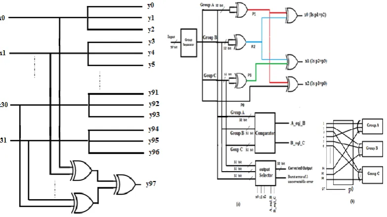
code uses enhanced decoding algorithm to correct all error patterns of one bit error, two bit errors and seven out of ten three bit error patterns. The proposed CAEDEC code has been compared with the existing error correction codes in terms of area, power consumption. It is observed that the proposed code provides 4.2% and 6 % improvement in area and power consumption respectively. The encoder and the decoder of the proposed CAEDEC code are shown in Figure 2 and Figure 3 respectively. The input bits are triplicated and and a parity bit is calculated for the triplicated bits and all
the bits are transmitted. The CAEDEC code is proposed in [10 ].
In decoder, all the bits are received and separated into three groups and parity bit. Parity is calculated for the three groups and compared with the sent parity to find the occurrence of error in the received bits.
3.2.2 Multi Bit Random and Burst Error Correction code with crosstalk avoidance (MBRBEC)
The proposed MBRBEC error correction code uses standard triplication error correction scheme to avoid crosstalk. Hamming single error correction-double error detection (SEC-DED) code is combined with triplication error correction scheme to correct all error patterns up to five bits using simple decoding logic. The encoder and the decoder diagram for the proposed MBRBEC error correction code are shown in Figure 4 and Figure 5 respectively. The 32 bit data is encoded using SEC-DED encoder and is triplicated. The triplicated data is transmitted. At the receiver, the data bits are received and separated into three groups. Each group is decoded using SCE-DED decoder to find the errors. The
MBRBEC code is proposed in [ 8 ].
Figure 4. MBRBEC Encoder Figure 5. MBRBEC decoder
3.2.3 Multiple Bit Error Correction code with Extended Hamming Product Codes (MBECEHPC)
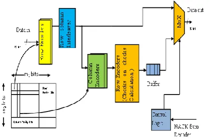
The proposed code uses extended Hamming Product code with Type II HARQ. Type II HARQ is combined with the product code. This reduces the number of interconnection links. The proposed error correction code uses extended Hamming product code combined with Type II HARQ as in [5]. The error correction code proposed in [5] uses a three stage decoding process (row decoding - column decoding - row decoding). But the proposed code MBECEHPC uses only a two stage decoding process (row decoding - column decoding). In the proposed code, keyboard scan based error flipping circuit is used to replace the third stage row decoding. The keyboard scan based decoding greatly reduces the hardware complexity. The proposed error correction code corrects burst errors up to six bits. The proposed code also corrects up to eight bit random errors if the occurrence of error is not more than two bit in each row and in each column.
Figure 6 and Figure 7 shows the encoder and decoder diagram for the proposed MBECEHPC code. This code has been
proposed in [9].
3.3 Incorporation of Error Correction Codes in the Custom Topology
The proposed custom topology generation algorithm generates custom topology for ASNoC that outperforms standard topologies and the existing custom topologies as regards area, power consumption and latency. However, it is also required to address the reliability of the custom topology. To augment the reliability of the custom topology, the proposed three error correction are incorporated in the custom topology to generate a reliable custom topology that corrects transient errors in the on-chip interconnection link. The incorporation of error correction codes are based on link level flow control and network level flow control. In link level flow control, also known as switch-to-switch flow control, encoder and decoder are placed in each port of the switch to correct errors [11]. Whereas, in network level flow, control also called end-to-end flow control, encoder and decoder are placed only in source NI and destination NI and not in intermediate switches [11].
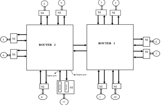
3.3.1 End-to-End Error Correction (Network Level) Scheme
In end-to-end error correction scheme, the encoder and decoder are placed only in NIs and not in the intermediate switches [11]. The diagram for end-to-end error correction scheme is shown in Figure 8. The encoder present in the source NI encodes the flit before placing it in the switch to which it is connected. The switch just receives the flit and forwards it to its neighbor without any encoding/decoding. This way, the flit is forwarded to the destination switch. The destination switch forwards the flit to the destination NI. After receiving the flit, the decoder present in the destination NI first decodes the flit to correct any errors and sends NACK or ACK signal depending on whether the received data has errors. If the received data has no errors then it is forwarded to the destination IP core. If it has errors, it asks for a retransmission of the data.
Figure 8. End-to-End error correction scheme
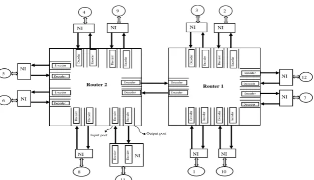
3.3.2 Switch-to-Switch Error Correction (Link Level) Scheme
In switch-to-switch error correction scheme, the encoder is placed in each output port of the switch and decoder in each input port of the switch as shown in Figure 9. The encoder and decoder are also placed in the NI [11]. In switch-to-switch error correction scheme, the encoder at the source NI encodes each flit received from the source IP core. The encoded flit is transmitted to the switch over an interconnection link. The decoder placed at the input port of the switch decodes the flit to correct any errors and asks for retransmission if the error occurrence needs retransmission. Then the flits are processed in the switch and sent to any output port based on the destination address. The output port which receives the flits, again encodes them before being placed over the interconnection link. The destination NI/switch decodes the received flit to correct errors before sending it to the destination IP core.
NI
12
NI
7 2
NI
3
NI
11
Output port Input port
En
co
d
er
D
ec
o
d
er
NI
10
NI
1
NI
9
NI
4
NI
6
NI
8
NI NI
5
Figure 9. Switch-to-switch error correction scheme
IV.RESULTS AND DISCUSSION
In this section, the area and power overhead of the custom topology embedded with the proposed three error correction coding schemes CAEDEC, MBRBEC, MBECEHPC and the existing error correction coding schemes CADEC, JTEC are compared with the original custom topology without error correction coding (Base custom topology). The comparison is performed for both end-to-end error correction and switch-to-switch error correction schemes at flit level. The custom topology is considered for the flit width of 32 bits and is synthesized in TSMC 0.18µm technology library. The base custom topology and the custom topology embedded with the error correction coding schemes are synthesized using the Cadence RTL encounter tool.
4.1 Performance Analysis of End-to-End Error Correction Scheme 4.1.1. Area and power consumption
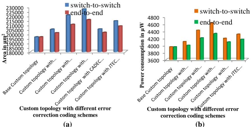
The custom topology embedded with the proposed CAEDEC, MBRBEC and MBECEHPC coding schemes have only 2%, 6% and 8% increase in area respectively compared to the custom topology without error correction coding (Base custom topology). Compared to the base custom topology, the custom topology embedded with the proposed CAEDEC, MBRBEC and MBECEHPC coding schemes have minimum power overhead of 1%, 5% and 9% respectively. Compared to the custom topology embedded with the existing error correction coding schemes CADEC, JTEC proposed by [12, 13], the custom topology embedded with the proposed MBRBEC and MBECEHPC coding schemes has a meager increase in area, power overhead, which is negligible compared to the high reliability of the proposed error correction schemes. The area and power overhead of end-to-end error correction scheme are shown in Figure 10.
4.1.2. Reliability
In end-to-end error correction schemes, error correction is performed only in destination NI and not in intermediate switches. Hence, in a high noise environment, there is a risk of errors being accumulated in the flits before reaching the destination. If the error correction code used is not powerful, many uncorrected flits (residual error flit) are left, increasing the residual flit error rate. Figure 11 shows uncorrected flits for end-to-end error correction scheme in both low and high noise environments. For simulation purposes, in each hop, up to two bit errors have been introduced in low noise environment and up to five bit errors have been introduced in high noise environment. The uncorrected flits in low noise environment for the proposed three error correction codes CAEDEC, MBRBEC and MBECEHPC are 80%, 10% and 20% respectively. The uncorrected flits in high noise environment for the proposed three error correction codes CAEDEC, MBRBEC and MBECEHPC are 100%, 60% and 70% respectively. Hence, in high noise environment, if a less powerful error correction code is used, many uncorrected flits are left. The reliability of the system is greatly reduced when end-to-end error correction scheme is used in high noise environment. Thus, it is recommended that, end-to-end error correction scheme with powerful error correction code can be used in low noise environment to achieve good protection against errors.
11 Output port Input port En co de r D ec od er E nc od er D ec od er NI 8 NI E nc od er D ec od er 6 NI Decoder Encoder 5 NI Decoder Encoder 9 NI E nc od er D ec od er 4 NI E nc od er D ec od er Decoder Encoder 2 NI E nc od er D ec od er 3 NI E nc od er D ec od er 12 NI Decoder Encoder 7 NI Decoder Encoder 10 NI E nc od er D ec od er 1 NI E nc od er D ec od er Encoder Decoder
(a)
(b)
Figure 10. Comparison of base custom topology and the custom topology embedded with different error correctioncoding codes (a) Area overhead (b) Power overhead
Figure 11. Reliability of the proposed error correction codes in end-to-end and switch-to-switch error correction scheme
4.2 Performance Analysis of Switch-to-Switch Error Correction Scheme 4.2.1 Area and power consumption
The custom topology embedded with the proposed CAEDEC, MBRBEC and MBECEHPC coding schemes have only 4%, 11% and 14% increase in area respectively compared to the base custom topology. Compared to the base custom topology, the custom topology embedded with the proposed CAEDEC, MBRBEC and MBECEHPC coding schemes have minimum power overhead of 3%, 10% and 13% respectively. Compared to the custom topology embedded with CADEC and JTEC coding proposed by [12, 13], custom topology embedded with the proposed MBRBEC coding and MBECEHPC coding, has a meager increase in area and power. The reason for this is that, the proposed MBRBEC coding and MBECEHPC coding schemes have high error correction capability which slightly increases the area and power overhead. The area and power overhead for switch-to-switch error correction scheme are shown in Figure 12.
4.2.2 Reliability
In switch-to-switch error correction scheme, error correction is performed in each port of the switch. Hence there is no risk of errors being accumulated in the flits. This increases the reliability of the system by reducing the residual flit error rate. Uncorrected flits for switch-to-switch error correction scheme in both low and high noise environments are shown in Figure 13. In switch-to-switch error correction scheme, in low noise environment, the proposed three error correction codes correct all errors in the flits. Hence, 100% error correction is achieved in low noise environment. However, in high noise environment, the proposed CAEDEC and MBECEHPC error correction schemes leave few
180000 185000 190000 195000 200000 205000 210000 215000 220000 225000 230000
Are
a
in µm
2
Custom topology with different error correction coding schemes
switch-to-switch
end-to-end
3600 3800 4000 4200 4400 4600 4800
P
o
w
er
co
ns
um
ptio
n
in
µW
Custom topology with different error correction coding schemes
switch-to-switch
end-to-end
0 50 100
Unco
rr
ec
ted
flits (
%)
Low Noise Environment High Noise Environment
uncorrected flits. The uncorrected flits for the proposed three error correction codes CAEDEC, MBRBEC and MBECEHPC in high noise environment are 70%, 0% and 20% respectively. Thus, it is recommended to use switch-to-switch error correction scheme in high noise environment to achieve higher error protection.
V.CONCLUSION
The proposed three error correction schemes CAEDEC, MBRBEC, MBECEHPC and the existing error correction codes are embedded in the proposed custom topology to protect it against transient errors. The custom topology with end-to-end error correction scheme achieves minor increase in area and power consumption compared to the custom topology with switch-to-switch error correction scheme. In switch-to-switch error correction scheme, error correction is performed in each hop. Hence, high reliability is achieved. Therefore, in a low noise environment, it is recommended that end-to-end error correction scheme can be used with powerful error correction code as it provides protection against errors with less area and power overhead. However, in a high noise environment, switch-to-switch error correction scheme ensures higher protection against errors at the cost of minor increase in area and power overhead compared to the end-to-end error correction scheme.
REFERENCES
[1] L. Benini, G and De Micheli, “Networks on chips: a new SoC paradigm,” IEEE Comput. Pp.70–78 , 2002.
[2] C. Constantinescu, “Treands and challenges in VLSI reliability”, IEEE Micro Vol. 23 (4) pp. 14–19, 2003.
[3] G. Lai, X. Lin and S. Lai, “GA based floorplan aware topology synthesis of application-specific network-on-chip, Proceedings of IEEE International Conference on Intelligent Computing and Intelligent System, Vol.2, pp.554-558, October-2010.
[4] Yu, Q “Dual-Layer Adaptive Error Control for Network-on-Chip Links” IEEE Transactions on Very Large Scale Integration (VLSI) Systems, vol. 20, no.7, pp.1304-1317, 2012.
[5] Fu, B and Ampadu, P “Error control combining Hamming and product codes for energy efficient nano scale on-chip interconnects”, IET Computers & Digital Techniques. vol. 4, no.3, pp. 251-261, 2010.
[6] Maheswari, M and Seetharaman,G, “Implementation of Application specific Network on chip Architectures on Reconfigurable Devices using Topology
Generation Algorithm with Genetic Algorithm based optimization Technique” K.R Venugopal and L.M Patnaik (Eds.): ICIP 2012, CCIS 292, pp. 436–445, Springer-Verlag Berlin Heidelberg,2012.
[7] Maheswari, Mand Seetharaman,G, “Design and implementation of Low Complexity Router for 2D mesh Network On Chip using FPGA’ In the proce. of
International conference on Embedded system application” Los vegas, USA, July-18th -21st , 2011.
[8] Maheswari, Mand Seetharaman,G,“Multi bit Random and burst error correction code with crosstalk avoidance for reliable on chip
interconnection links” Microprocess. Microsyst - Elsevier Journal. vol. 37, no. 4-5, pp.420-429, 2013.
[9] Maheswari, Mand Seetharaman,G, “Hamming Product Code Based Multiple Bit Error Correction Coding Scheme Using Keyboard Scan Based Decoding for
On Chip Interconnects Links” Applied Mechanics and Materials Journal,vols. 241-244, pp 2457-2461, 2013.
[10] Maheswari, M and Seetharaman, G “Enhanced Low complex Double Error Correction Code with crosstalk avoidance for reliable on chip interconnection link”,
Journal of Electronic Testing-Theory and Applications (JETTA)- Springer Journal, Vol. 30, No. 4, pp.387-400, 2014. [11] Murali, S , “Methodologies for Reliable and Efficient Design of Networks-on-Chips. Ph.D Thesis, Stanford University, 2007.
[12] Ganguly, A, Pande, PP, Belzer, B , “Crosstalk-Aware Channel Coding Schemes for Energy Efficient and Reliable NOC Interconnects”, IEEE Trans. Very Large Scale Integr. (VLSI) Syst., vol. 17, no. 11, pp. 1626-1639, 2009.
[13] Ganguly, A, Pande, PP, Belzer, B and Grecu, C, “Design of low power & reliable networks on chip through joint crosstalk avoidance and multiple error correction coding”, Journal of Electronic Testing: Theory and Appl. (JETTA), Special Issue on Defect and Fault Tolerance, pp. 67–81, 2008.
[14] Lai, G and Lin, X , “Floor plan aware application specific network on chip topology synthesis using Genetic Algorithm technique”, The Journal of super computing, vol. 61, no. 3, pp. 418-437, 2012.
[15] Majeti, D, Pasalapudi, A and Yalamanchili, K , “Low Energy Tree Based Network On Chip Architectures using Homogeneous Routers for Bandwidth and Latency constrained Multimedia Applications”, Proceedings of ICETET-2009, pp. 358-363, 2009.
[16] Ge, F, Wu, N, Qin, X and Zhang, Y, “Performance- and Cost-Aware Topology Generation Based on Clustering for Application-Specific Network on Chip”, International journal of computer science,vol.39, no.1, pp. 1-10, 2012.
[17] Murali, S, Meloni, P, Angiolini, F, Atienza, D, Carta, S, Benini, L, Micheli, GDe and Raffo, L, “Designing Application Specific Network on Chips with Floorplan Information” Proceedings of ICCAD, pp. 355 - 362, 2006.
[18] Rossi, D, Nieuwland, AK, Katoch, A and Metra, C, “Exploiting ECC redundancy to minimize crosstalk impact’, IEEE Design & Test of Computers” vol. 22, no. 1, pp. 59–70, 2005.
[19] Rossi, D, Nieuwland, AK, Van Dijk, SVE, Kleihorst, RP and Metra, C , “Power consumption of fault tolerant busses’, IEEE Trans. Very Large Scale Integr. (VLSI) Syst”, vol. 16, no. 5, pp.542–553, 2008.
[20] Fu, B and Ampadu, P , “A multi-wire error correction scheme for reliable and energy efficient SoC links using Hamming product codes”, Proceedings SoCC, pp. 59–62, 2008.
[21] Fu, B and Ampadu, P , “An energy-efficient multi-wire error control scheme for reliable on-chip interconnects using Hamming product codes”, VLSI Design, vol., doi:10.1155/2008/109490, article ID: 109490, pp. 1–14, 2008.
[22] Fu, B and Ampadu, P , “On hamming product codes with type-II hybrid ARQ for on-chip interconnects”, IEEE Trans. Circuits Syst. I, Reg. Papers., vol. 56, no. 9, pp. 2042–2054, 2009.
BIOGRAPHY