The cloud of geographically distributed data
centers
PetrFedchenkov1, *,Andrey Shevel1,2,SergeyKhoruzhnikov1,OlegSadov1,Oleg Lazo1, Nikita Samokhin1
1ITMO University, 197101 St. Petersburg, Russia
2National Research Centre "Kurchatov Institute" Petersburg Nuclear Physics Institute, 188300
Gatchina, Russia
Abstract. ITMO University (ifmo.ru) is developing the cloud of geographically distributed data centres. The ™geographically distributed∫ means data centres (DC) located in different places far from each other by hundreds or thousands of kilometres. Usage of the geographically distributed data centres promises a number of advantages for end users such as opportunity to add additional DC and service availability through redundancy and geographical distribution. Services like data transfer, computing, and data storage are provided to users in the form of virtual objects including virtual machines, virtual storage, virtual data transfer link.
1 Introduction
The number of geographically distributed data centres (DC) grows each year. Quite often new DCs are located in cold regions of the world to save money and energy for cooling. An important criterion for the location of DC©s is the availability of electrical power. In some of the best locations, access to expert staff is limited. It is probably better to maintain DC without permanent staff. To manage such DCs, a distributed operating management system (DOMS) is needed. The DOMS must be able to control many virtual objects like virtual machines, virtual data links, virtual storage to form an IaaS cloud. Due to geographical distribution, the requirements for system stability in terms of hardware and software malfunctions are high. These are defined through specific Service Level Agreements (SLA).
In our solution, the DC is considered to be a group of hardware and/or virtual servers which is dedicated to run the user virtual machines (VM) and/or storage servers. Each pair of DCs may be interconnected by one or more virtual data transfer links. The program system OpenVPN [1] is used to provide data tunnels between DCs located far from each other.
In designing the DOMS, we employ:
•Free and Open Source Software (FOSS) for DOMS components;
•Software Defined Networking (SDN);
•Software Defined Storage (SDS);
•Infrastructure as Code (IaC).
The DOMS requires a specific combination of operating system, cloud system, storage organization and networking. Many aspects of the specific components selection are out of scope of this paper. DOMS uses the following essential software components: OpenStack [2,3] as a cloud platform, Ceph [4] as a storage subsystem, SaltStack [5] as an IaC engine and many other program systems. The NauLinux [6] is used as an operating system.
2 The structure of Developed distributed management system
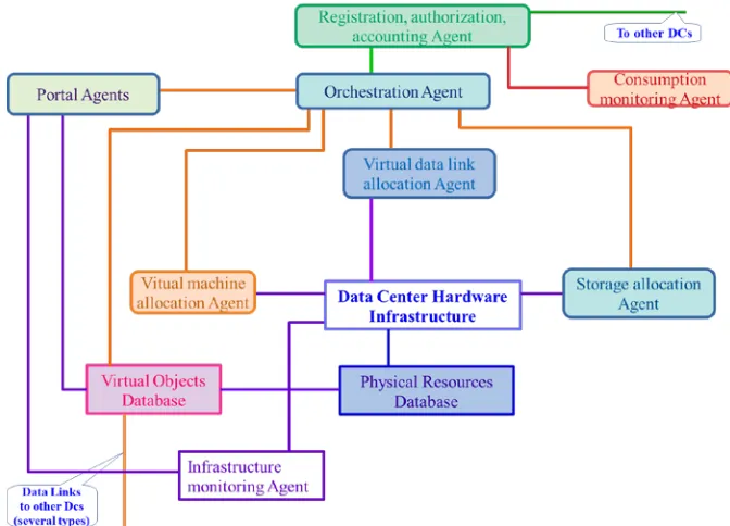
DOMS with mentioned features has been implemented in the form of software agents (daemons) running in an isolated operating environment like a VM or containers. Agents are interconnected by distributed messages queues as shown in fig. 1. Each agent has a certain functionality within the system. An interaction between agents is performed with a queuing technology, i.e. by sending and receiving the messages from the queues. Any agent is able to send the request (in the message form) to do specific action (or to provide a service) to other agent and to receive the answer (in the message form) with a developed protocol. The protocol was specifically developed within this project as means of communication between agents. It was designed to trace all the queries and to keep the queries history.
Fig. 1.The Distributed Operating Management System structure.
The agents perform management functions for certain parts of the cloud:
•Software Defined Networking (SDN);
•Software Defined Storage (SDS);
•Infrastructure as Code (IaC).
The DOMS requires a specific combination of operating system, cloud system, storage organization and networking. Many aspects of the specific components selection are out of scope of this paper. DOMS uses the following essential software components: OpenStack [2,3] as a cloud platform, Ceph [4] as a storage subsystem, SaltStack [5] as an IaC engine and many other program systems. The NauLinux [6] is used as an operating system.
2 The structure of Developed distributed management system
DOMS with mentioned features has been implemented in the form of software agents (daemons) running in an isolated operating environment like a VM or containers. Agents are interconnected by distributed messages queues as shown in fig. 1. Each agent has a certain functionality within the system. An interaction between agents is performed with a queuing technology, i.e. by sending and receiving the messages from the queues. Any agent is able to send the request (in the message form) to do specific action (or to provide a service) to other agent and to receive the answer (in the message form) with a developed protocol. The protocol was specifically developed within this project as means of communication between agents. It was designed to trace all the queries and to keep the queries history.
Fig. 1.The Distributed Operating Management System structure.
The agents perform management functions for certain parts of the cloud:
• The registration, authorization, accounting (RAA) agent is an important component but is out of scope of this paper;
• Orchestration Agent checks incoming requests (usually from RAA agent, from the others occasionally) for operation, redirects requests to other agents, controls execution process, aggregates results and sends them back to the requester;
• Storage allocation Agent prepares a VM for storage clusters deployment, performs deployment, creates a gateway for different types of access, and implements the forwarding of an external port for access to the storage;
• Virtual machine allocation Agent loads the images, deploys user' s virtual machines, configures a network name space and/or a network segment for access from the outside and between data centers;
• Virtual data link allocation Agent configures network switches for the user' s VM data transmission between data centers, implements data encryption and encoding to guarantee a specific SLA;
• Portal Agents provide the resources state information in a readable form and allow users to interact with the cloud in accordance with user credentials;
• Infrastructure monitoring Agent interacts with infrastructure equipment to observe and notify possible equipment degradation;
• Utilization monitoring Agent collects information about the actual resources utilization by a user or a group of users for accounting and billing.
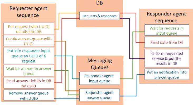
A request from the agent is sent to the specific message queue which is also associated with another specific agent (each agent has an associated input queue). All requests are written in JSON format and includes timestamp with a time zone, request type, etc. Each request is divided into two parts: the first part, the short one, is sent over RabbitMQ [7] message broker. The second part (which may be large) is written to a well-defined SQL database. The message sent in the queue is quite short: timestamp, request id, return queue. All the other potential parameters are written to the request database. After the agent receives the request and performs the validation check, it reads all request parameters from the request database and after another validation procedure it starts processing the received request. The request database is configured with High Availability (HA) options. The interaction scheme between agents is shown in Figure 2.
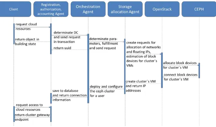
The user may create and use one or more virtual object(s) with the help of a cloud portal. Each user request for the virtual object should be checked for its feasibility of deployment and integration with existing objects and restrictions in the cloud. An example of a user storage cluster creation sequence diagram is shown in fig. 3. A creation process involves a number of agents of the presented platform. In this case, the interaction between the system agents is performed asynchronously through the message queue and the database using the described protocol. The described scheme prevents the losses even in case of unplanned shutdown/restart.
Fig. 3.User storage cluster creation sequence diagram
3 The development of the Data Center structure and the current
testbed
Our testbed consists of 10 HPE DL380 Gen10 host servers and 4 HP FF 5700 network switches with OpenFlow support. The equipment is located within a single room, but the network configuration is formed with three micro DCs (4-3-3 servers).
Fig. 4.Testbed connectivity.
Special measures were undertaken to simulate geographical distribution for the micro DC. OpenVPN in the OSI Layer 2 is configured so that the OpenVPN client program is running on each of the micro DCs. The OpenVPN server program is located 1,500 Km distant and connected via the public Internet as shown in fig. 4.
The underlying network architecture is the general basis for everything: virtual machines, storages, data transfer.
Two basic Ceph clusters have been created to implement Software Defined Storage (SDS): one cluster connected to the Cinder OpenStack module is used as a backend for block devices of user' s virtual machines and the other is used for service storage. Service storage is divided by fixed size extents and used as the disk drives for many Ceph clusters to form user data storage ± this provides separate cluster for separate users. In reality, any user storage is implemented as Ceph-over-Ceph. The time overheads are in the limit of 5%-10% depending on configuration.
Two cloud OpenStack platforms (two separate OpenStack instances) have been created to be used as a service cloud and a user cloud (Fig. 5). The virtual machines for storage are created in the OpenStack service and launched by the storage allocation agent. The deployment of Ceph clusters with the required subnets for each client request to allocate Virtual Storage are implemented automatically. A user out of DOMS can access the created virtual storage over a special front-end gateway which is also connected to all the gateways of the user' s Ceph clusters. This approach provides block, file, and object access types. An S3-compatible interface for object storage and a Nextcloud [8] application for file storage access are supported as well.
Having separate Ceph cluster for each user' s virtual storage increases the reliability of the storage and the isolation between clients.
Fig. 5.DC OpenStack instances, Ceph, agents interconnections.
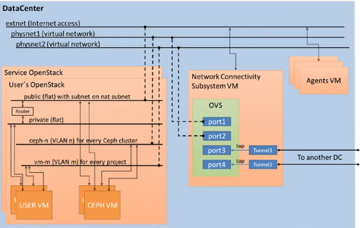
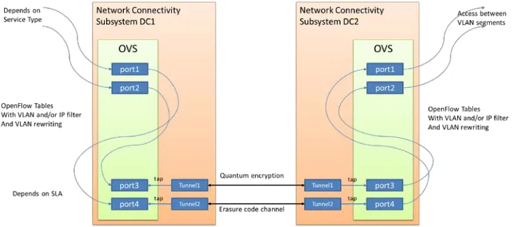
4 Connectivity scheme between VM running in different DCs
parallel transmission and data encoding including using keys from quantum generators of coding sequences [9]. The selection of a specific codec is determined by the selection of a data link. The data link is switched with the help of SDN [10] in order to implement the specified SLA for data transfer between data centres.
Fig. 6.Connectivity scheme
Figure 6 shows the scheme of the described approach for data transfer between DC. The Open vSwitch [11] is managed by a virtual data links allocation agent. It consists of subsystems, such as a RYU controller [12] and an application for the controller.
The allocation agent creates a virtual network interface for the TAP kernel driver and emulates an Ethernet device for operation on the L2 layer of the OSI model. This network interface is added to the Open vSwitch in order to redirect the network packets according to rules issued by the controller. After converting according to the SLA, the Ethernet packets are transmitted to another DC. Each tunnel defines the data link required to implement the requested SLA.
5 Conclusion
The structure and its main components of geographically distributed data centres cloud were developed. The proof-of-concept of a multi-agent system for managing virtual resources is presented. The scheme of a network connectivity has been designed to provide the specified SLA for data transfer between data centres. The virtual storage allocation procedure has been implemented by creation of user Ceph clusters within service Ceph cluster, i.e. Ceph-over-Ceph.
Main advantages of the designed system:
• The structure consists of isolated program agents:
o No interference between agents on type/version of used program libraries;
o It is easy to change program system inside the specific agent, for example, to use EOS [13] instead Ceph;
o Increasing the number of agents serving the same input queue allows horizontal scalability;
o One agent is down does not mean the whole DOMS is down.
• The requests/answers protocol, which prevents the losses in complicated cases.
The developed features may be helpful for implementation of multi DC cloud of IaaS type, for HEP needs especially.
Acknowledgment
This research has been carried out with the financial support of the Ministry of Education and Science of the Russian Federation (project № 03.G25.31.0229)™Development of new technological components for management systems of geographically distributed Data Centers∫.
References
1. OpenVPN. Available at: https://openvpn.net (accessed 3 Febrary 2019)
2. Fedchenkov P.V., Khoruzhnikov S.E., Grudinin V.A., Sadov O.L., Shevel A.Y., Kairkanov A.B., Lazo O.I., Oreshkin A.A. Service reliability in the cloud of data centers under Openstack // CEUR Workshop Proceedings - 2017, Vol. 2023, pp. 282-287
3. Sefraoui, O., Aissaoui, M., & Eleuldj, M. (2012). OpenStack: toward an open-source solution for cloud computing. International Journal of Computer Applications, 55(3) 4. T. Bell, B. Bompastor, S. Bukowiec, J. Castro Leon, M. K. Denis, J. van Eldik, M.
Fermin Lobo, L. Fernandez Alvarez, D. Fernandez Rodriguez, A. Marino, B. Moreira, B. Noel, T. Oulevey, W. Takase, A. Wiebalck, and S. Zilli. 2015. Scaling the CERN OpenStack cloud. J. Phys. Conf. Ser. 664, 2 (2015), 022003.
5. SaltStack. Available at: https://www.saltstack.com/resources/community (accessed 7 Febrary 2019).
6. Scientific Linux. Available at: http://www.scientificlinux.org/community/based-on-sl (accessed 12 Febrary 2019).
7. RabbitMQ. Available at: https://www.rabbitmq.com (accessed 2 Febrary 2019) 8. Nextcloud. Available at: https://nextcloud.com (accessed 3 September 2018)
9. Chistyakov, V. V., Sadov, O. L., Vasiliev, A. B., Egorov, V. I., Kompaniets, M. V., Fedchenkov, P. V., ... & Khoruzhnikov, S. E. (2017). Software-defined subcarrier wave quantum networking operated by OpenFlow protocol. arXiv preprint arXiv:1709.09081
10. Diego Kreutz at al // Software-Defined Networking: A Comprehensive Survey // Proceedings of the IEEE ( Volume: 103 , Issue: 1 , Jan. 2015 ) // pages 14 - 76 // DOI:10.1109/JPROC.2014.2371999
11. Ben Pfaff at al // The Design and Implementation of Open vSwitch // 12th USENIX Symposioum on Networked Systems Design and Implementation // May 4-6, 2015, OACLAND CA // full text in PDF is available at https://www.usenix.org/conference/nsdi15/technical-sessions/presentation/pfaff
(accessed 1 Febrary 2019)
12. Component-based software defined networking framework. Available at: http://osrg.github.io/ryu/ (accessed 1 Febrary 2019)
13. EOS STORAGE. Available at: https://eos.com/eos-storage (accessed 7 Febrary 2019). 14. Justin Riley, John Noss, Wes Dillingham, James Cuff, Ignacio M. Llorente, "A