The KM3NeT Digital Optical Module and Detection Unit
RonaldBruijn1,2,∗on behalf of the KM3NeT collaboration
1Universiteit van Amsterdam, Instituut voor Hoge-Energie Fysica, Science Park 105, 1098 XG
Ams-terdam, The Netherlands
2Nikhef, Science Park, Amsterdam, The Netherlands
Abstract.The KM3NeT Collaboration is constructing new-generation neutrino detectors in the Mediterranean Sea. The main goals are the study of the high-energy neutrino flux and the determination of the neutrino mass ordering. The basic detection element, the Digital Optical Module (DOM), houses 31 3-inch PMTs inside a 17-inch glass sphere. The aim is to measure photons emitted by products of neutrino interactions in the sea-water with nanosecond precision. The multi-PMT concept has many advantages over a single-PMT design. We will discus these aspects and the enabling technologies. Additionally, the re-quired mechanical and optical/electrical system on which DOMs are deployed
as vertical strings, called Detection Units will be discussed.
1 Introduction
The KM3NeT collaboration is constructing two large volume neutrino detectors in the Mediterrean Sea. By detecting the Cherenkov light caused by the product particles from neutrino interactions in the sea-water, the collaboration aims to study the nature of the flux of high-energy neutrinos with an astrophysical origin and to determine the ordering of the neu-trino mass-eigenstates [1]. The first goal will be persued with the KM3NeT/ARCA detector, which is being constructed off-shore of Capo-Passero, Sicily, with a Gigaton scale instru-mented volume at 3.5 km depth. The second goal is the main aim of the KM3NeT/ORCA detector, which is to be about 4 Megaton and located at 2.5 km depth off-shore of Toulon, France. Here we will present two of the main technical innovations that the KM3NeT col-laboration has designed and implemented to achieve these goals. First is the Digital Optical Module (DOM), which houses the photo-multipliers. KM3NeT/ARCA will consist in its full configuration (phase-2) of about 4140 DOMs, while KM3NeT/ORCA will have about half that number of DOMs. The second is the Detection Unit (DU) which implements a mechani-cal structure and electro-optimechani-cal infrastructure to arrange 18 DOMs in a vertimechani-cal configuration, which is about 700 meters high for KM3NeT/ARCA and about 200 m for KM3NeT/ORCA. The design and implementation as used inphase-1of KM3NeT is presented here.
2 Digital Optical Module
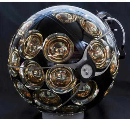
The basis of the KM3NeT Digital Optical Module [2] is a pressure resistant glass sphere that houses 31 3-inch PMTs. This design has many advantages over a single, large, PMT
design and leverages the good optical properties of Mediterranean seawater, in particular the long scattering lengths. The design allows to fit 3 times the equivalent photo-cathode area of a single 10-inch PMT in a 17-inch sphere. The segmentation allows to extract directional information of the photon flux, and photon-counting can be done to first order by counting the number of PMTs that registered a photon. Suppression of ambient background photons can be aided by requiring coincidences. The DAQ is based around the all-data-to-shore principle. Hit times and pulse widths of all recorded photons are sent to shore via optical Ethernet in timeslices of 100 ms where a CPU farm applies trigger algorithms to extract signals from a 7 kHz per PMT background. This explicitly exploits the good optical properties as the information in the photon arrival time is not diluted by scattering.
Figure 1 shows a DOM.
Figure 1. A partial side-view of a KM3NeT Digital Optical Module. The bottom hemisphere, where 19 of the 31 PMTs are located, is oriented to the bottom left of the photo.
2.1 Mechanics
The 17-inch diameter borosilicate glass sphere is supplied in two halves which are joined after integrating the mechanics and instruments. The top hemisphere contains a mechanical structure which provides a thermal conduit to the water via the glass and forms a mechanical basis for the rest of the components and much of the electronics. The PMTs are housed in 3D printed support structures. The bottom support structure houses 3 rings of 6 PMTs and 1 PMT pointing straight down. The top support structure has 2 rings of 6 PMTs. The support structure also holds reflector rings around the PMTs, a pressure gauge and a led beacon. Importantly, the structures form a barrier for the silicone gel that is between the glass and the PMTs. The top hemisphere has a drilled hole into which a feedthrough (penetrator) for two copper wires and one or two optical fibres is mounted. The penetrator is an own design and essentially consists of a titanium flange into which a ceramic plug is mounted. The production is moved to industry where proprietary technologies are used for the plug (’seal’) which is either epoxy of low-meltingpoint glass. A titanium collar is mounted around the assembled sphere and is used to mount the DOM on the DU.
2.2 Instruments
The PMT dimensions are specified to maximize the photo-cathode area per DOM and are about 3 inch in diameter and have reduced length. The main timing specification is a transit-time spread of smaller than 2 ns RMS, while the quantum efficiency is above 23% at 404 nm and above 18% at 470 nm. The dark count rate at 0.3 photo-electron level should not exceed 2kHz, but is typically found to be much smaller than 1 kHz. In order to minimize the aging of the PMTs, which have an in-situ counting rate of about 7 kHz, a relatively low gain of about 3·106is required at a typical operating voltage of about a kV. The PMT used is the Hamamatsu R12199. For future expansions also PMTs by ETL and HZC are considered. A piezo-acoustic hydrophone, primarily for acoustic positioning, is glued to the inside of the glass. A compass and tiltmeter mezzanine board which communicates via I2C provides orientation data.
2.3 Electronics and Data Acquisition
The main electronics boards are the Powerboard, the Central Logic Board (CLB), the signal collection boards and the PMT bases. The powerboard converts the incoming 12V to the needed voltages of 1, 1.8, 2.5, 3.3 (2 times) and 5 V via high-efficiency DC/DC convert-ers and contains current sensors. At the back of the PMTs aPMT Baseboard is mounted. This board contains a Cockroft-Walton circuit driven by a custom designed application-specific-integrated-circuit which provides the required and adjustable high-voltage from the 3.3 V input. A second custom ASIC contains a pre-amplifier, comparator and low-voltage-differential-signal (LVDS) driver to turn the PMT pulse into a digital signal which is high while the pulse is above a adjustable threshold. This ASIC also allows for I2C communica-tion with the PMT to set its values and read-out its unique identifier. Two signal colleccommunica-tion boards, one for the lower and one for the upper hemisphere route the PMT signals to the CLB and provide a connection for the piezo-electric hydrophone. The CLB houses a Xil-inx Kintex FPGA which implements the whole data-acquisition chain, time synchronization, Ethernet communication and slow-control. Two CPUs are implemented, of which one is dedicated to two-way communication with shore to allow for control and monitoring of the hardware. The firm- and software of the FPGA can be updated over Ethernet from shore via a fail-safe procedure. The CLB host a small-formfactor-pluggable cage in which a laser transceiver is mounted with a defined from the ITU grid with a 50 GHz spacing. A led flasher with its driver board is mounted under the glass on the top hemisphere and is connected to the CLB which provides settable triggers and power up to 30V. The total power-use of a DOM in operation is less than 7.5 Watt.
2.4 Integration
3 Detection Unit
A Detection Unit (DU) is the structure that arranges 18 DOMs in a vertical line and pro-vides connection to the sea-floor opto-electrical network. A Vertical-Electro-Optical-Cable (VEOC) contains optical fibres and two copper leads and connects to the base-container. The mechanical backbone of a DU consists of two 4 mm thin Dyneema ropes. At the top the two ropes are connected to a open-cell foam buoy. Each DOM provides about 11 kg of buoy-ancy. In the ARCA configuration the vertical spacing between the DOMs is about 38 meters, while in the ORCA configuration this is about 9 meters. The VEOC consists of a 7 mm wide flexible polyethylene tube filled with oil. This is thus an pressure balanced system. At every DOM, in a break-out box, also pressure-balanced, one fibre is split of and a DC/DC converter steps down from about 400V to the 12V for the DOM. Spacing rods are placed along the line and the VEOC is guided via clips and sliders. A 3D printed mechanism provides correct guid-ing of the VEOC durguid-ing the deployment process. The rope system provides limited intrinsic correction of DOM orientation in case of minor misalignments or due to dynamic forces. The anchor keeps the DU in place due to its weight and houses the wet-mateable connector for the interlink cable that connects to the sea-floor network. The cylindrical base-container contains the power, power-protection and timing electronics and the optical components to amplify the optical signal and to multiplex the 18 channels of the DOMs onto a single fibre. Two way communication with the container allows for control and monitoring of the signal and for powering up and down the DU. The DU also houses an acoustic transmitter and receiver for acoustic positioning.
3.1 Deployment system
As the ropes cannot support the weight of the anchor and in particular to allow for rapid deployment of multiple DUs, a dedicated deployment device, called the LOM, is used. This is a spherical structure of 2m diameter with three lanes that can hold each 6 DOMs, the ropes, VEOC and supporting mechanics and has dummy glass spheres for buoyancy. This assembly, with the DOMs and ropes wound around it, is mounted on the anchor of the DU and the buoy is positioned through the vertical axis. This assembly can be deployed from a ship, after which an submersible remotely operated robot connects it to the sea-floor network and pulls a rope to release the LOM. While the LOM rolls upwards, the DOMs exit the device and the line completely unfurls. The LOM floats to the surface and is recovered.
3.2 Integration
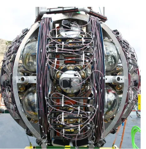
The integration of a DU is modular so that the subsequent steps can take place at different integration sites. The first step is attaching the DOMs to the VEOC, which involves optical splicing, electrical connections, closing the break-out-boxes, followed by leak testing and filling with oil. Each DOM has an assigned position within a DU and there are 4 types of DU. This organization is linked to the undersea opto-electrical network where channels are combined on a smaller set of optical fibres. Other steps are attaching a feed-through for 18 fibres and 400V carrying copper cables to the VEOC, called a base-penetrator. The titanium base-container is assembled separately, and is joined with the VEOC assembly. The result-ing assembly can be tested and calibrated in a dark-room. The final procedure consists of attaching the ropes, additional mechanics and buoy and installation on the LOM and anchor. This procedure is done in one step, meaning that the ropes are attached while winding the DU around the LOM (actually, the LOM rotates). The resulting package ’DU stack’ is then ready for deployment, see Figure 2.
Figure 2.A LOM loaded with a Detection Unit ready to be deployed. Three DOMs can be seen in the center, between the lanes that hold the VEOC and ropes.
4 Deployments
After shallow water tests and a prototype DOM [3] on an Antares string, a prototype DU was deployed in May 2014 [4] . In December 2015 the first full length ARCA DU was installed at the Italian site. Since then 3 DUs have been operational, of which one of the ORCA type at the French site. Currently the collaboration is constructing the first phase of KM3NeT and preparing and acquiring components for the second phase.
References
[1] S. Adrian-Martinezet al.[KM3NeT Collaboration], J. Phys. G43(2016) no.8, 084001 [2] R. Bruijn and D. van Eijk, PoS ICRC2015(2016) 1157.