ISSN 2348 – 7968
Mechanical and Microstructure properties of Pulsed Tungsten Inert
Gas and FS Welding of AA5083 Butt joint
B. Ravindar1, Dr. K. Gururaj2 , Dr.A. Somi Reddy3
1
Department of Mechanical Engineering, Vaageswari college of Engineering, Karimnager, India1.
Department of Mechanical Engineering. Kakatiya Institute of Technology & Science, Warangal, India2.
Department of Mechanical Engineering, Vivekananda Institute of Technology & science, karimnagar, India3.
bhanothuravindar@gmail.com1, yadav_56@yahoo.co.in2 ,arumalle_reddy@yahoo.co.in3
Abstract
This study has been conducted to investigate the effect of welding process parameter on the mechanical properties and microstructure of aluminum alloy 5083, using Pulsed Tungsten inert gas welding (P/TIG) and friction stir welding (FSW). In this study, Pulse TIG welding parameter’s on weldability of 5083 alloy specifications. The welding parameters such as welding current, Gas flow rate, and different filler diameters are taken into account which influences the properties of material at welded area. Aluminium 5083 sheets were welded by Pulse Tig welding with 5356. To determine the effects of friction stir welding (FSW) parameters, which are the tool rotation speed, Welding speed, Tool tilt angle for the same material. The effect of welding process parameters is analyzed by conducting of mechanical properties and micro structure tests on weld joint for TIG welded samples as well as FSW samples. The experimental results indicate that the welding process parameters have significant effect on mechanical properties of the joints, compare with Pulsed Tig welding we got fsw best results at Tool Rotational speed 900 rpm, welding speed 80 mm/min and angle of the tool is 910. The mechanical properties and micro hastucture results shows that FSW joint is better than Pulsed Tig welding.
Keywords: AA 5083 plates, Tensile test, Impact test, Micro structure Properties, straight cylindrical pin, Butt Joint.
1. Introduction
Tig welding is an arc welding process that uses a non – consumable tungsten electrode to produce the weld. The weld area is protected from atmosphere by an inert shielding gas (argon or helium) and a filler metal is normally used. The power is supplied from the power source (rectifier), through a hand piece or welding torch and is delivered to a tungsten electrode which is fitted into the hand piece. An electric arc is then created between the tungsten electrode and the work piece using a constant
currant welding power supply that produces energy and conducted across the arc through a column of highly ionized gas and metal vapors. The tungsten electrode and the welding zone are protected from the surrounding air by inert gas.. The welding came into existence from “Bronze Age” about 2000 years ago. But Egyptian people learned to weld iron pieces together during Iron Age. TIG Welding is preferred only for aluminium alloys because it starts to spread out from weld pool during the welding operation in other processes.TIG welding was demonstrated first by Russell Meredith in 1930 during Second World War for welding aluminum and magnesium in aircraft industry. Tig welding with Pulsating current has been known for many years. The welding current weaves periodically between a high (pulse current) and low (basic current) values. In the basic current phase, the low temperature causes a decrease in the volume of the molten pool. The welding has applications in manufacturing field such as ships, boats, cyclic, automotive industry, aircraft industry and pipelines. The weld quality was strongly characterized by weld bead geometry because the weld pool geometry plays an important role in determining mechanical properties of weld. Maximum quality can be achieved with control of welding parameters and material and material used must be cleaned. The heat affected zone influenced with the increment of heat input due to increased welding current. The width of heat affected zone increases due to low heat input. The weld bead geometry of weld repaired aluminium alloy was similar as cast aluminium alloy in appearance but different in micro-structure.
ISSN 2348 – 7968 most often on large pieces which cannot be easily heat
treated post weld to recover temper characteristics. Friction Stir Welding (FSW) is a solid state joining process that involves joining of metals without fusion or filler materials. The frictional heat is produced from a rapidly rotating non-consumable high strength tool pin that extends from a cylindrical shoulder. The process is particularly applicable for aluminium alloys but can be extended to other products also. Plates, sheets and hollow pipes can be welded by this method. The process is also suitable for automation. The weld produced is of finer microstructure and superior in characteristics to that parent metal. FSW finds application in shipbuilding, aerospace, railway, electrical and automotive industry. The limitations of FSW are reduced by intensive research and development. Its cost effectiveness and ability to weld dissimilar metals makes it a commonly used welding process in recent times. Friction Stir Welding (FSW) is a solid state welding process first discovered and patented by the Welding Institute of Cambridge U.K.in 1991 [1-2]. FSW technique is attractive for joining high strength aluminium alloys since there is far lower heat input during the process compared with conventional welding processes such as TIG, MIG[3-4], which include being a single step process, use of simple and inexpensive tool, less time consuming, no finishing process requirement, less processing time, use of existing and readily available machine tool technology, suitability to automation, flexibility to robot use, being energy efficient and environmental friendly [5]. This process is being used in wide variety of applications in the automotive, aerospace, ship building, and railroad industries [6]. In FSW the interaction of a non-consumable and rotating tool with the work pieces being welded, creates a welded joint through frictional heating and plastic deformation at temperatures below the melting temperature of the alloys being joined. Based on friction heating at the contacting surfaces of two sheets to be joined, a special tool with a properly designed rotating probe travels down the length of
contacting metal plates, producing a highly plastically deformed zone through the associated stirring action [7]. The probe is typically slightly shorter than the thickness of the work piece and its diameter is typically slight larger than the thickness of the work pieces [8]. Interesting benefits of FSW compared to fusion process es are low distortion, excellent mechanical properties in the weld zone, execution without a shielding gas, and suitability to weld all aluminium alloys [9]. Fixture is used to hold the sample plates which are welded by FSW process on the bed of CNC milling machine. Sample plates have to be clamped because these plates are to undergo high mechanical forces during the process. Special fixture is design as per requirements [10-11].
1.1Introduction to Aluminium Alloy 5083
Aluminium is a chemical element in the boron group with symbol Al and atomic number 13. It is silvery white, and is not soluble in water under normal circumstances. Aluminium is the third most abundant element (after oxygen and silicon), and the most abundant metal, in the Earth’s crust. It makes up about 8% by weight of the Earth’s solid surface. Aluminium metal is so chemically reactive that native specimens are rare and limited to extreme reducing environments. Instead, it is found combined in over 250 different minerals. The main ore of aluminum is bauxite. Aluminium is remarkable for its low density and ability to resist corrosion due to the phenomenon of passivation. Structural components made from aluminum and its alloys are vital to the aerospace industry and are important in other areas of transportation and structural materials. The most useful compounds of aluminium, at least on a weight basis, are the oxides and sulphates. Aluminium 5083 is a high strength non-heat treatable alloy in commercial use. The major additive in the alloy is Magnesium. It has good formability and weldability and retains excellent tensile strength in the weld zone. It has excellent resistance to corrosion and high strength-to-weight ratio. The experimental material is selected as 5083 Al alloy sheets of 4 mm thickness, which is welded by Friction Stir Welding after surface preparation
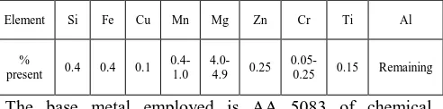
Table 1: Chemical Composition AA 5083
Element Si Fe Cu Mn Mg Zn Cr Ti Al
%
present 0.4 0.4 0.1
0.4-1.0
4.0-4.9 0.25
0.05-0.25 0.15 Remaining
The base metal employed is AA 5083 of chemical composition is shown in Table 1. Mechanical properties and Physical properties are shown in Table 2 and 3.
Table 2: Mechanical Properties of AA 5083
Property(Mpa) Value
Tensile Strength(MPa) 330
Shear Strength(MPa) 185
Elongation (%) 17
ISSN 2348 – 7968
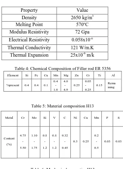
Table 3: Physical Properties of AA 5083
Table 4: Chemical Composition of Filler rod ER 5356
Element Si Fe Cu Mn Mg Zn Cr Ti Al
%present 0.4 0.4 0.1 0.4 - 1.0
4.0 - 4.9
0.25 0.05 - 0.25
0.15 Rema ining
Table 5: Material composition H13
Metal Cr Mo Si V C Ni Cu Mn P S
Content (%)
4.75 - 5.50
1.10 - 1.75
0.8 - 1.2
0.8 - 1.2
0.32 - 0.45
0.3 0.25 0.2
- 0.5
0.03 0.03
Table 6: Mechanical properties H13
2.EXPERIMENTAL WORK
Pulsed current gas tungsten arc welding, developed in 1950’s, is a variation of gas tungsten arc welding which involves cycling of the welding current from a high level to a low level at a selected regular frequency. The high level of peak current (Ip) is generally selected to give adequate penetration and bead contour, while the low level of background current (Ib) is set at a level sufficient to maintain a stable arc.
This permits arc energy to be used efficiently to fuse a spot of controlled dimensions in a short time producing the weld as a series of over lapping nuggets and limits the wastage of heat by conduction into the adjacent parent material as in normal constant current welding, the fact that heat energy required to melt the base material is supplied only during peak current pulses for brief intervals of time allows the heat affected zone (HAZ). The technique has secured a niche for itself in specific applications such as in welding of root passes of tubes and in welding thin sheets, where precise control over penetration and heat input are required to avoid burn through.
For friction stir welding and tig welding same metal i.e AA 5083 sheets, 4 mm thickness for butt joint is used. For tig welding different diameters of electrodes are use and the material is 5356 i.e same composition as base metal. For tig welding a vertical semiautomatic milling machine was used. The tool used for this process was made of H13 steel 18mm diameter with the length of the pin is 4.7mm. Firstly material cut by shear machine as required dimensions of 100 x 100 x 4 mm are prepared and weld was made by joining two pieces. The process of welding is FSW completed by one pass by using H13 steel and weld samples of weld at different conditions by changing one parameters and keeping two parameter constant such that total number of samples are 27 from each welding.
Table 7. TIG welding process parameters
Table 8. FSW Process parameter
Property Value
Density 2650 kg/m3
Melting Point 570oC
Modulus Resistivity 72 Gpa
Electrical Resistivity 0.058x10⁻⁶
Thermal Conductivity 121 W/m.K
Thermal Expansion 25x10-6 m/k
Properties Content (%)
Ultimate Tensile Strength
(@ 200 c) 1200-1590 Mpa
Yield Strength (@ 200 c) 1000-1380 Mpa Reduction of Area (@ 200 c) 50%
Modulus of Elasticity (@ 200 c) 31200 ksi
Poisson’s Ratio 0.27-0.3
Specimen Id
Welding current
(Amps) Gas Flow Rate ( Lt/min)
Filler rod dia.(mm)
3 180 8 3.2
15 210 10 3.2
27 240 12 3.2
Specimen
Tool Rotational
speed(rpm) Welding Speed (mm/min)
Angle of the Tool (degrees)
3 700 60 91
15 900 80 91
ISSN 2348 – 7968
Figure 1:Schematic diagram of gas welding
Figure 2: Friction stir welding Tool H13 and Tool geometry
Figure 3:Before welding clapping & Alignment
Figure 4: Experimental setup
Fig 5: Samples with Weld bead and fsw
Figure 6: Impact and tensile Test Welded samples
cut by EDM
Fig. 7: Tensile and Impact Samples after test 2.1 TENSILE TEST RESULTS
Table 9:Base Metal
Sl.No. Tensile strength (N/mm2)
Yield strength
((N/mm2) % Elongation
1 296 170 21
Table 10:Tensile test result of sample id
Specimen Id
Average values of mechanical properties Tensile strength
(N/mm2)
Yield strength
(N/mm2) % Elongation
TIG FSW TIG FSW TIG FSW
3 152 265 122 159 3 7
15 107 257 86 153 2 5
ISSN 2348 – 7968
Figure 8:Base metal
TIG.03 FSW.03
Tig 15 Fsw 15
Tig 27 Fsw 27
Figure 9: Stress strain curves of FSW and P TIG welding for different samples
296
170
21
152 122
3 265
159 7 0
100 200 300 400
Base Metal TIG FSW
Figure 10: Relationship between base metal, Pulsed TIG welding for sample -3
296
170
21
107 86
3 257
153 5 0
100 200 300 400
Base Metal TIG FSW
Figure 11: Relationship between base metal, Pulsed TIG welding for sample - 15
296 170
21 107 86
3 257
153 5 0
100 200 300 400
Base Metal TIG FSW
Figure 12: Relationship between base metal, Pulsed TIG welding for sample - 27
2.2 Impact energy test results Table 11:base metal
Sample ID. Impact Energy - Joules
BASE METAL 14 – J
Table 12: impact energy of test id
Sample Id
Pulse TIG FS WELDING
Impact Energy - Joules Impact Energy - Joules
I - 003 6 - J 12 - J
I - 015 12 - J 12 - J
I - 027 14 – J 10 - J
0 5 10 15
Impact energy
Base Metal TIG FSW
ISSN 2348 – 7968
10 12 14 16
Impact energy
Base Metal TIG FSW
Figure 14:Bar diagram for Pulsed TIG & FSW of Sample 15
0 5 10 15
Impact energy
Base Metal TIG FSW
Figure 15:Bar diagram for Pulsed TIG & FSW of Sample 27
Figure 16:Base Metal AA 5083
100X Weld 100X Weld
100X HAZ 100X HAZ Figure 17:Microstructures for sample Id: 3
100X Weld 100X Weld HAZ
100X HAZ 100X HAZ Figure 18:Microstructures for sample Id: 15
100X HAZ 100X HAZ
100X Weld 100X Weld Figure 19:Microstructures for sample Id:27
3.CONCLUSIONS
1. The tensile test showed that the FSW joint
exhibits superior tensile properties performance as compared with TIG welding. The sound welds have been obtained using FSW for 4 mm thickness of aluminium alloy AA 5083. TS of the welded joints and base metal produced adequate tensile strength values.
2. The FSW welded joints having a non- dendrite microstructure, whereas the microstructure of TIG welded joints contains dendrites. Because of dynamic recritallization in the FS welding. The nugget contains fine and fragmented grain compared to the TIG welded joint. The fusion zone of TIG welded joints contain dendritic structure and this may be due to fast heating of base metal and fast cooling of molten metal. 3. While a comparison between the base metal and
stir zone indicating by FSW we can see a fine, equated grains due to temperature difference between tool shoulder side and base mental size and the tool centerline.
4. Test sample method of impact testing does
ISSN 2348 – 7968 larger grain size of the welded joints and
precipitate distribution.
5. The stirring effect of FSW improved the
microstructure of the weld. From the observation of Scanning Electron Microscope (SEM) an appreciable difference exists in the size and shape of the dimples with respect to welding processes.
REFERENCES
[1] C. J. Dawes and W. M. Thomas. “Friction stir process welds of aluminium alloys”, Welding Journal, pp. 41-45, 1996.
[2] W. M. Thomas, E. D. Nicholas, J. C. NeedHam, M. G. Murch, P. Templesmith and C. J. Dawes, “Improvements relating to Friction Stir Welding”, International patent application no. PCT/GB92/02203, 1992.
[3] M. Ericsson and R. Sandstro, “Influence of welding speed on the fatigue of friction stir welds, and comparison with MIG and TIG”, International Journal of Fatigue, pp. 1379-1387, 2003.
[4] W. M. Thomas, E. D. Nicholas, E. R. Watts and D. G. Staines, “Friction based welding technology for aluminium”, Material Science Forum, pp. 1543-1548, 2002
[5] K. Kumbhar, S. V. Kailas and T. S. Srivatsan, “Influence of tool geometry in Friction Stir Welding”, Material and Manufacturing Process, pp. 189-195, 2008 [6] K. H. Rendigs., “Aluminium structures used in aerospace-status and prospects”, Material Science Forum, pp. 11-24, 1997
[7] W. J. Arbegast. “Friction stir welding after a decade of development”, Welding Journal, pp. 28-35, 2007
[8] V. Soundararajan, E. Yarrapareddy and K. Radovan, “Investigation of the friction stir lap welding of aluminum alloys AA 5182 and AA 6022”, Journal Material science Engineering Perform, pp. 477-484, 2007
[9] L. Zhao, H. J. Liu and Q. W. Liu, “Effect of rotation speed on microstructure and mechanical properties of Ti– 6Al–4V friction stir welded joints”, 2010.
[10] R. S. Mishra, Z. Y. Ma, “Friction stir welding and processing”, Material Science Engineering, pp. 1- 78, 2005 [11] R. M. Mishra and M. W. Mahoney, “Friction stir welding & processing”, ASM International, pp. 360, 2007 [12] A. Sidana, K. Sandhu and B. Singh, “Effect of tool rotation speed on microstructure properties of friction stir welded Al6061-T6 alloys”, International Journal of New Innovation, pp. 295-299, 2012
[13] S. Cam, A. Gucluer, A Cakan and H. T. Serindag, “Mechanical properties of Friction Stir butt-welded Al-5086 H32 plate”, Journal of Achievements in Materials and Manufacturing Engineering, pp. 151-156, 2008
[14] G. Singh, K. Singh and D. Jaiswal , “Mathematical modelling of process parameter in FSW of aluminium alloy.’ National conference
on advancements & futuristic trends in mechanical and materials engineering, pp. 57, 2010
Mishra RS, Mahoney MW (2007) Friction stir welding and processing. Materials Science and Engineering: Reports 1– 352
[15] Zhou C, Yang X, Luan G (2006) Investigation of microstructures and fatigue properties of friction stir welded Al–Mg alloy. Materials Chemistry and Physics 98(2-3):285–290
[16] Ericsson M, Sandstrom R (2003) Influence of welding speed on the fatigue of friction stir welds, and comparison with MIG and TIG. International Journal of Fatigue 25(12):1379–1387
[17] Chen C., Kovacevic R (2004) Joining of Al 6061 alloy to AISI 1018 steel by combined effects of fusion and solid state welding. International Journal of Machine Tools and Manufacture 44(11):1205–1214
[18] Lee WB, Schmuecker M, Mercardo UA, Biallas G, Jung SB (2006) Interfacial reaction in steel–aluminum joints made by friction stir welding. Scripta Materialia 55(4):355–358