ABSTRACT
ZHANG, FAN. Towards Development of a Novel Neural-machine Interface for Powered Artificial Legs. (Under the direction of Dr. He Huang).
The usefulness and importance of different data sources which have been commonly suggested for locomotion mode recognition were investigated in Chapter 2. The considered data sources included eight surface EMG signals from residual thigh muscles, ground reaction forces/moments from a prosthetic pylon, and kinematic measurements from residual thigh and prosthetic knee. We ranked the included data sources based on the usefulness for locomotion mode recognition and selected a reduced number of data sources that ensured accurate locomotion recognition by using three source selection algorithms. The results showed that not all of the studied data sources carried important information and input redundancy do exist in the initial design of fusion-based interface. Importantly, the results suggested that EMG signals and ground reaction forces/moments were more informative than prosthesis kinematics. The selected data sources generated consistent performance across different experimental days, indicating the potential robustness of the selected data sources. In addition, we suggested a protocol for determining the informative data sources and sensor configurations for future powered artificial leg design.
Towards Development of a Novel Neural-machine Interface for Powered Artificial Legs
by Fan Zhang
A dissertation submitted to the Graduate Faculty of North Carolina State University
in partial fulfillment of the requirements for the degree of
Doctor of Philosophy
Biomedical Engineering
Raleigh, North Carolina 2015
APPROVED BY:
_______________________________ ______________________________ Dr. He Huang Dr. Gregory S. Sawicki
Committee Chair
________________________________ ________________________________ Dr. David S. Lalush Dr. Michael D. Lewek
DEDICATION
I would like to dedicate my dissertation work to my family, with a special feeling of gratitude to my loving parent, Heping Zhang and Jinfeng Wang. Thank you so much for all your support, encouragement, and endless love throughout my life. I love you!
This work is also dedicated to my advisor, Dr. He Huang. Thank you for your constructive suggestions, insightful criticism, and encouragement throughout my graduate studies.
BIOGRAPHY
Fan Zhang was born in Taiyuan, Shanxi, China in November 1981 and graduated from high school in the summer of 2001. Fan received his Bachelors of Science in Biomedical Engineering from Tianjin Medical University, China, in the summer of 2006, and Masters of Science in Biomedical Engineering from Tianjin University, China, in the summer of 2008. During his two-year graduate study, he was involved in research about design and optimization of rehabilitation walker system in the NeuroEngineering and Rehabilitation Laboratory at Tianjin University. Through this research opportunity, he gained solid knowledge and great interests in biomedical and rehabilitation engineering field.
ACKNOWLEDGMENTS
I would like to express my deepest gratitude to all individuals for their contribution to this dissertation work:
My advisor, Dr. He Huang. Without your continuous support and invaluable
guidance, I can never accomplish my doctoral research. There are no appropriate words to express my special thanks.
All Neuromuscular Rehabilitation Engineering Laboratory (NREL) members. Thank
you for all the great assistance and suggestions throughout my graduate research. My doctoral committee members: Dr. Gregory S. Sawicki, Dr. David S. Lalush, Dr.
Michael D. Lewek, and Dr. Fen Wu. Thank you for agreeing to serve on my committee. You are more than generous with your expertise and precious time.
Michael Nunnery, CPO, at the Nunnery Orthotic and Prosthetic Technology LLC,
Stephen Harper, CPO, and Derek Frankena, CP, at Atlantic Prosthetics & Orthotics, LLC. Thank you for your great help with amputee patient recruitment, design and fabrication of experimental prosthetic sockets. Without your help, none of these works would be possible.
Finally, I would like to thank the following federal funding agencies for supporting this research:
National Science Foundation (NSF/ECCS & CISE)
National Institutes of Health (NIH/NICHD)
TABLE OF CONTENTS
LIST OF TABLES ... vi
LIST OF FIGURES ... vii
CHAPTER 1: General Introduction ...1
1.1 Motivation ...1
1.2 Powered Artificial Legs and Control Strategy ...3
1.3 Overview of User Intent Recognition Algorithm based on Neuromuscular- Mechanical Fusion ...6
1.4 Objective and Summary of Research ...14
References ...16
CHAPTER 2: Source Selection for Real-time User Intent Recognition towards Volitional Control of Artificial Legs ...20
2.1 Abstract ...20
2.2 Introduction ...21
2.3 Methods...24
2.4 Results ...39
2.5 Discussion ...46
2.6 Conclusion ...49
References ...50
CHAPTER 3: Effects of Locomotion Mode Recognition Errors on Volitional Control of Powered Above-Knee Prostheses ...54
3.1 Abstract ...54
3.2 Introduction ...55
3.3 Methods...58
3.4 Results ...71
3.5 Discussion ...78
3.6 Conclusion ...84
References ...85
CHAPTER 4: General Conclusion and Future Work ...88
4.1 General Conclusion ...88
LIST OF TABLES CHAPTER 1: General Introduction
Table 1. The Number of Missed Transitions among All Tested Mode Transitions
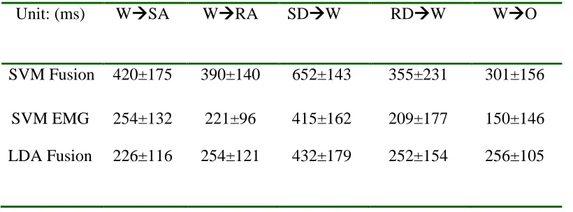
...12 Table 2. The Prediction Time of Mode Transitions before the Critical Event ..12
CHAPTER 2: Source Selection for Real-time User Intent Recognition towards Volitional Control of Artificial Legs
Table 1. Demographic Information of Four Subjects with Transfemoral Amputations (TF01-TF04)...27
Table 2. The Source Selected for Four Recruited TF Subjects (TF01-TF04) ..41 Table 3. Average Task Transition Prediction Time across Subjects in the First and Second Real-time Experiments ...45 CHAPTER 3: Effects of Locomotion Mode Recognition Errors on Volitional Control of Powered Above-Knee Prostheses
LIST OF FIGURES CHAPTER 1: General Introduction
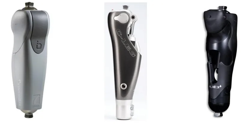
Figure 1. Examples of commercially available microprocessor knees ...2 Figure 2. Examples of commercialized and research prototypical powered knees ...3
Figure 3. Architecture of the neuromuscular-mechanical fusion based locomotion mode recognition algorithm ...6
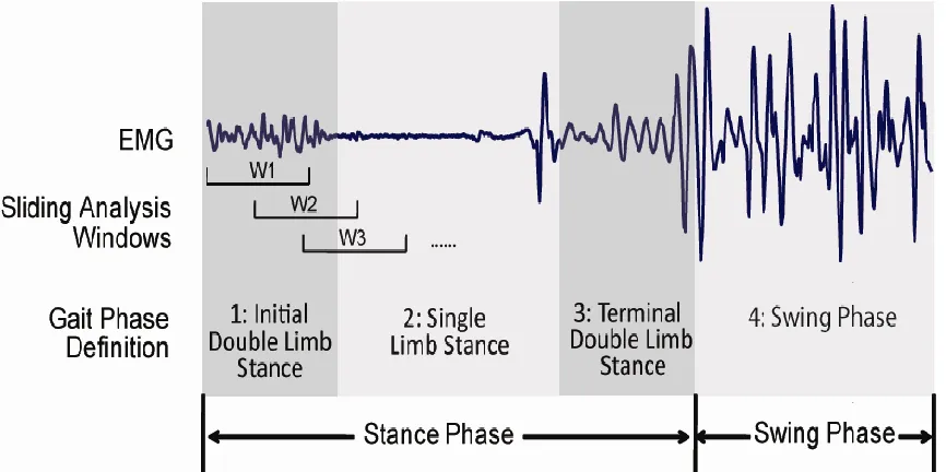
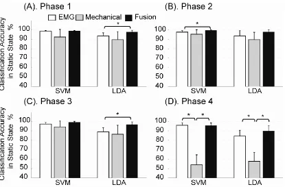
Figure 4. Data windowing scheme and definition of gait phases in one stride cycle ...7 Figure 5. Classification accuracy in the static state averaged over five TF amputees ...11 Figure 6. Example of continuous mode identification decisions from a representative trial that recorded a transition from level-ground walking and stair ascent ...13 CHAPTER 2: Source Selection for Real-time User Intent Recognition towards Volitional Control of Artificial Legs
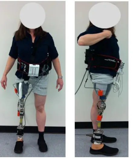
Figure 1. Experimental setup on one transfemoral amputee subject (TF01) ...28
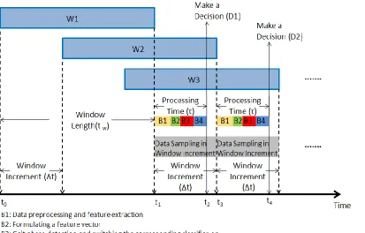
Figure 2. Continuous windowing scheme and time sequence for real-time implementation of user-intent-recognition interface ...33
Figure 3. Accuracy of intent recognition in static states when the number of selected data sources increased ...40 Figure 4. Intent recognition accuracy in static states ...44 CHAPTER 3: Effects of Locomotion Mode Recognition Errors on Volitional Control of Powered Above-Knee Prostheses
CHAPTER 1:
General Introduction
1.1 Motivation
Limb amputation is a devastating event that has physical, psychological, and social impact on people’s daily life. There were nearly 1.6 million people living with limb loss in the United States in 2005 [1], with lower limb amputations occurring much more frequently than upper limb amputations. Due to the aging of the population and increasing rates of dysvascular disease related to diabetes and obesity, there are approximately 185,000 new limb amputees in the United States each year [2]. It was estimated that the total number will be more than doubled by the year 2050 to 3.6 million [1]. Therefore, there is a pressing need to restore as much function as possible to the large and increasing population of limb amputees. The targeted patient population of this research is transfemoral (TF) amputees (or above-knee amputees). It is not only because they have the second largest amputee population, but also they are a more challenging group in which case they lost both their knee and ankle joints, which makes restoration of mobility and function even more difficult.
sliding joints or hydraulic valves) and the body movement of user’s trunk, pelvis, and
residual limb. Microprocessor controlled prostheses (e.g. Ossur Rheo Knee, Otto Bock C-Leg, and the Freedom Innovations Plié knee, as shown in Figure 1) incorporate mechanical sensors and a microcontroller, and modulate the joint damping throughout the gait cycle by controlling either hydraulic [3] or magnetic rheological fluid [4]. These passive devices do provide lower limb amputees with increased mobility; however, they still have limited capability to assist lower limb amputees to negotiate uneven terrains (i.e. stairs and ramps) in a natural and efficient way, due to the lack of active net power on prostheses joints. In addition, it has been shown that transfemoral amputees with passive prosthetics expend up to 60% more metabolic energy [5] and exert three times of hip power and torque [6] during level-ground walking, compared to able-bodied persons.
1.2 Powered Artificial Legs and Control Strategy
Recent advancements in microcomputer-controlled, powered artificial legs have greatly increased the number of locomotive functions that lower limb amputees can perform [7-10]. One commercially available powered knee (i.e. Ossur Power Knne) and two representative research prototypes are shown in Figure 2. With powered prosthetics driven by active actuators, lower limb amputees can more easily and efficiently perform a variety of activities, such as stair climbing and slope walking, which are difficult or even impossible when they wear traditional passive devices. Powered artificial legs usually employ a finite-state machine
(FSM) based intrinsic control mechanism to adjust the joint impedance or joint position during ambulation [10, 11]. In addition, the control is mode-based [9, 10], which means prosthesis needs to switch control modes according to user’s different performing tasks, such
as level-ground walking and stair ascent. Therefore, to seamlessly transition from one task to another, the user must “tell” the prosthesis his/her movement intention before performing the
transitions so that the controller of the prosthesis can switch to correct mode in time. Conventional manual mode switching approach, such as pressing a remote key fob [3] or performing extra body motions [7], is functionally viable; however, the manual approaches are non-intuitive and cumbersome, sometimes unreliable and unsafe.
Alternatively, several smarter approaches, which automatically recognize prostheses users’ movement intention, have been explored to allow more intuitive control. One approach
intention. Task transitions among level walking, sitting, and standing were investigated and tested on one patient with transfemoral (TF) amputation. The study reported 100% accuracy in recognizing the mode transitions and only 6 misclassifications during a 570s testing period. In addition, over 500ms system delay was reported, which may be inadequate for smooth control of prosthetic legs during transitions between dynamic locomotion modes.
1.3 Overview of User Intent Recognition Algorithm based on Neuromuscular-Mechanical Fusion
Although the results reported in [23] were promising, an increase in classification accuracy is desired to ensure the safety and reliability of powered artificial leg control. Inspired by the previous studies, our group proposed a novel locomotion mode recognition algorithm based on neuromuscular-mechanical fusion [24]. The idea was to combine the surface EMG signals recorded from residual thigh muscles and the mechanical sensing measurements from prosthetic legs to further improve the user intent recognition accuracy. The architecture of the fusion-based algorithm is demonstrated in Figure 3 [24].
data in one defined gait phase. The corresponding classifier was switched on based on the output of the designed gait phase detector. Four clinical gait phases (i.e. initial double stance, single limb stance, terminal double stance, and swing phase) are defined and detected by using mechanical sensor readings from prosthesis, as shown in Figure 4. In design of the pattern classifier, a linear classification method, i.e. linear discriminant analysis (LDA) [15, 16, 26] and a non-linear classification algorithm, i.e. support vector machine (SVM) [27, 28] were applied and compared. A post-processing algorithm, i.e. majority vote scheme, was applied to the decision stream to produce smoothed decision continuously.
between different locomotion tasks were captured. The data collected during the experiment was then used for offline evaluation of the proposed algorithm.
Due to difficulty in defining a moment that can clearly separate two task modes during dynamic task transitions, the performance of the algorithm was quantified in static states and transitional period separately. Static states were the states when subjects continuously performed the same task. In static states, the accuracy of locomotion mode identification was calculated as a quantification index. A transitional period was defined as the period when subjects switched locomotion modes, which included a full gait cycle and two stance phases of the amputated leg. The transitional period started at initial prosthetic foot contact before stepping on the upcoming terrain and terminated at the end of single stance phase after the transition. During transitional periods, the ability of the algorithm to accurately recognize stable transitions and the timing of predicting transitions were evaluated.
Table 1.
The Number of Missed Transitions among All Tested Mode Transitions No. of Missed
Transitions
TF01 TF02 TF03 TF04 TF05
SVM Fusion 0 0 0 0 0
SVM EMG 2 1 1 0 3
LDA Fusion 3 1 1 0 3
Note: The total number of tested task transitions was 75 for each subject.
Table 2.
The Prediction Time of Mode Transitions before the Critical Event
Unit: (ms) WSA WRA SDW RDW WO
SVM Fusion 420±175 390±140 652±143 355±231 301±156
SVM EMG 254±132 221±96 415±162 209±177 150±146 LDA Fusion 226±116 254±121 432±179 252±154 256±105
1.4 Objective and Summary of Research
Design of an effective and robust intent recognition algorithm, which can accurately and reliably recognize the prosthesis user’s intended locomotion tasks and predict the task
transitions, is one of the essential cores in developing a neural-machine interface for artificial leg control. To make the interface clinically viable for safe and reliable prosthesis operation, there are still several challenges need to be addressed.
REFERENCES
[1] K. Ziegler-Graham, E. J. MacKenzie, P. L. Ephraim, T. G. Travison, and R. Brookmeyer, “Estimating the prevalence of limb loss in the United States: 2005 to 2050,” Arch Phys Med Rehabil, vol. 89, no. 3, pp. 422-9, Mar, 2008.
[2] N. C. f. H. Statistics, Ambulatory and Inpatient Procedures in the United States: US Department of Health and Human Services, Centers for Disease Control and Prevention, National Center for Health Statistics, 1998.
[3] I. O. B. O. Industry, “Manual for the 3c100 Otto Bock C-LEG,” Duderstadt, Germany, 1998.
[4] “OSSUR, RHEO KNEE, http://bionics.ossur.com/Products/RHEOKNEE/ACT.” [5] R. Waters, J. Perry, D. Antonelli, and H. Hislop, “Energy cost of walking of
amputees: the influence of level of amputation,” J Bone Joint Surg Am, vol. 58, no. 1,
pp. 42-46, 1976.
[6] D. Winter, “The biomechanics and motor control of human gait: normal, elderly and pathological, 1991,” Waterloo Biomechanics, Graphic Services.
[7] OSSUR, The POWER KNEE, The POWER KNEE ed.:
http://bionics.ossur.com/Products/POWER-KNEE/SENSE. [8] iWalk, “BiOM Ankle System,” http://iwalk.com/home.html.
[10] F. Sup, A. Bohara, and M. Goldfarb, “Design and Control of a Powered Transfemoral Prosthesis,” Int J Rob Res, vol. 27, no. 2, pp. 263-273, Feb 1, 2008.
[11] E. C. Martinez-Villalpando, and H. Herr, “Agonist-antagonist active knee prosthesis: a preliminary study in level-ground walking,” J Rehabil Res Dev, vol. 46, no. 3, pp. 361-73, 2009.
[12] W. C. Flowers, and R. W. Mann, “Electrohydraulic knee-torque controller for a prosthesis simulator,” ASME J. Biomech. Eng., vol. 99, no. 4, pp. 3-8, 1977.
[13] S. Bedard, and P. Roy, Actuated leg prosthesis for above-knee amputees, U. S. Patent 7 314 490, 2003.
[14] H. A. Varol, F. Sup, and M. Goldfarb, “Multiclass real-time intent recognition of a powered lower limb prosthesis,” IEEE Trans Biomed Eng, vol. 57, no. 3, pp. 542-51,
Mar, 2010.
[15] B. Hudgins, P. Parker, and R. N. Scott, “A new strategy for multifunction myoelectric control,” Biomedical Engineering, IEEE Transactions on, vol. 40, no. 1, pp. 82-94,
1993.
[16] K. Englehart, and B. Hudgins, “A robust, real-time control scheme for multifunction myoelectric control,” Biomedical Engineering, IEEE Transactions on, vol. 50, no. 7,
pp. 848-854, 2003.
[17] G. N. Saridis, and T. P. Gootee, “EMG pattern analysis and classification for a prosthetic arm,” Biomedical Engineering, IEEE Transactions on, no. 6, pp. 403-412,
[18] G. Li, A. E. Schultz, and T. A. Kuiken, “Quantifying pattern recognition—Based myoelectric control of multifunctional transradial prostheses,” Neural Systems and
Rehabilitation Engineering, IEEE Transactions on, vol. 18, no. 2, pp. 185-192, 2010. [19] K. H. Ha, H. A. Varol, and M. Goldfarb, “Volitional control of a prosthetic knee
using surface electromyography,” Biomedical Engineering, IEEE Transactions on,
vol. 58, no. 1, pp. 144-151, 2011.
[20] L. J. Hargrove, A. M. Simon, R. D. Lipschutz, S. B. Finucane, and T. A. Kuiken, “Real-time myoelectric control of knee and ankle motions for transfemoral amputees,” JAMA, vol. 305, no. 15, pp. 1542-1544, 2011.
[21] L. Peeraer, B. Aeyels, and G. Van der Perre, “Development of EMG-based mode and intent recognition algorithms for a computer-controlled above-knee prosthesis,”
Journal of biomedical engineering, vol. 12, no. 3, pp. 178-182, 1990.
[22] D. Jin, J. Yang, R. Zhang, R. Wang, and J. Zhang, “Terrain identification for prosthetic knees based on electromyographic signal features,” Tsinghua Science &
Technology, vol. 11, no. 1, pp. 74-79, 2006.
[23] H. Huang, T. A. Kuiken, and R. D. Lipschutz, “A strategy for identifying locomotion modes using surface electromyography,” IEEE Trans Biomed Eng, vol. 56, no. 1, pp.
65-73, Jan, 2009.
[25] B. Hudgins, P. Parker, and R. N. Scott, “A new strategy for multifunction myoelectric control,” IEEE Trans Biomed Eng, vol. 40, no. 1, pp. 82-94, Jan, 1993.
[26] H. Huang, P. Zhou, G. Li, and T. A. Kuiken, “An analysis of EMG electrode configuration for targeted muscle reinnervation based neural machine interface,”
Neural Systems and Rehabilitation Engineering, IEEE Transactions on, vol. 16, no. 1, pp. 37-45, 2008.
[27] M. A. Oskoei, and H. Hu, “Support vector machine-based classification scheme for myoelectric control applied to upper limb,” Biomedical Engineering, IEEE
Transactions on, vol. 55, no. 8, pp. 1956-1965, 2008.
CHAPTER 2:
Source Selection for Real-time User Intent Recognition towards
Volitional Control of Artificial Legs
Fan Zhang, He Huang
As published in IEEE Journal of Biomedical and Health Informatics
2.1 Abstract
in real time. The selected data sources produced consistent system performance across two experimental days for four recruited TF amputee subjects, indicating the potential robustness of the selected data sources. Finally, based on the study results, we suggested a protocol for determining the informative data sources and sensor configurations for future development of volitional control of powered artificial legs.
2.2 Introduction
Limb loss is a physically and emotionally devastating event that renders people less mobile and at risk for loss of independence. It has been estimated that 664,000 persons have been living with major limb loss in the U.S. in 2005 [1], with lower limb amputations occurring much more frequently than upper limb amputations. With the increasing incidence of dysvascular amputations, the number of lower limb amputations in the U.S. is expected to increase to 58,000 per year by 2030 [2, 3]. Therefore, there is a pressing need to restore as much function as possible to the large and increasing population of lower limb amputees.
Recent advances in powered artificial legs [4-6] have allowed lower limb amputees to efficiently perform activities that are difficult or impossible when wearing passive devices (e.g. climbing a staircase). However, smoothly switching tasks (e.g. from level-ground walking to stair ascent) has been difficult for patients wearing powered prostheses. This is due to the lack of a user interface that can identify the user’s intent. Because the control parameters in current powered artificial legs are modulated by the user’s performing tasks
approach, we have termed neuromuscular-mechanical fusion, outperformed the approaches based on only EMG signals or mechanical measurements.
Various types of data sources including EMG signals recorded from residual limbs and ground reaction forces/moments measured from prosthetic pylon have been fused together to recognize user intent for volitional control of powered artificial legs. However, there is still a debate on what exact data sources are necessary for accurately and responsively recognizing the user’s intended tasks. Although the fusion of multiple data sources have demonstrated
performance improvement over the approaches using single data sources, the use of a large number of data inputs would complicate the design of the instrumented prostheses, the intent-recognition algorithm, and the hardware necessary for its real-time application on powered artificial legs. Therefore, further investigation is needed to identify the informative data sources, reduce the number of system inputs, and create a more efficient real-time intent-recognition interface for artificial legs.
The goals of this study were to (1) investigate the usefulness of different data sources commonly suggested for user intent recognition, and (2) determine an informative set of data sources for volitional control of prosthetic legs. In this study, we first implemented our previously designed neuromuscular-mechanical-fusion interface in real time. We then ranked included data source based on the usefulness for user intent recognition and selected a reduced number of data sources that ensured accurate recognition of the user’s intended task
the source selection. Finally, this study suggested a protocol for determining the informative data sources and sensor configurations for future development of volitional control of powered artificial legs.
2.3 Methods
2.3.1 Participants and Experimental Measurements
This study was conducted with Institutional Review Board (IRB) approval and the written, informed consent of all the recruited subjects. Two male and two female patients with unilateral TF amputations (TF01–04) were recruited (see Table 1). All subjects were regular prostheses users.
additional EMG sites were selected where strong signals could be recorded when the subject performed hip flexion/extension, hip adduction/abduction, or executed knee flexion/extension. When executing knee flexion/extension, the subjects were asked to attempt to flex/extend their amputated knee joints. The electrodes contained a preamplifier that band-pass filtered the EMG signals between 10 and 2000 Hz with a band-pass-band gain of 20. The EMG electrodes were embedded in customized gel liners (Ohio Willow Wood, US) for both the users’ comfort and reliable electrode-skin contact. A 16-channel EMG system (MA 300,
Motion Lab System, US) was used to collect EMG signals. The cut-off frequency of the anti-aliasing filter for EMG channels was 450 Hz. Mechanical ground reaction forces (Fx, Fy, Fz) and moments (Mx, My, Mz) were measured by a six-degree-of-freedom (DOF) load cell (PY6, Bertec Corporation, OH, US) mounted on the prosthetic pylon, with the x, y, and z
axes aligned with the mediolateral, superoinferior, and anteroposterior axes of the subject, respectively. Both analog EMG signals and mechanical load values were sampled at 1000 Hz by a data acquisition board (DATAQ DI-720, DATAQ Instruments, Inc., Ohio, US). In addition, two inertial measurement units (IMUs) (Xsens Technologies B.V., Enschede, Netherlands) were used to measure the kinematics of the prosthesis. Both IMUs were tightly affixed to the lateral side of the prosthetic socket and pylon. The IMUs’ coordinate systems
were aligned with the coordinate system of the load cell in the standing position. A total of 12 kinematic data were derived from the IMU measurements, including three-DOF linear accelerations of the thigh segment (TAcc_x, TAcc_y, TAcc_z), angular velocity (TAV_x,
the residual thigh segment and prosthetic knee were specifically monitored because (1) motion of the residual thigh is still controlled by a transfemoral amputee and therefore represents the user’s voluntary control, (2) the selected kinematic parameters of the
Table 1.
Demographic Information of Four Subjects with Transfemoral Amputations (TF01-TF04)
Age Weight (kg) Height
(cm) Gender
Years post-amputation
Residual limb
length ratio* Prosthesis for daily use
TF01 40 65.7 162.6 F 31 68% RHEO Knee
TF02 49 71.2 170.1 M 12 93% C-Leg
TF03 54 64.0 164.0 F 33 84% RHEO Knee
TF04 59 75.8 175.3 M 23 51% RHEO Knee
2.3.2 Real-time User Intent Recognition
The architecture of our neuromuscular-mechanical-fusion interface has been previously reported [15]. The multichannel data are preprocessed and segmented into analysis windows. Features believed to capture the signal patterns are extracted and fused into one feature vector. The feature vector is then fed to a phase-dependent pattern classifier, composed of a gait-phase detector and multiple sub-classifiers corresponding to individually defined gait phases for mode recognition. The classification decisions are further post-processed to improve system accuracy. There are two procedures involved in real-world application of the intent-recognition interface: (1) offline training and (2) real-time testing. In this study, both procedure were implemented and tested using MATLAB (The Mathworks, Massachusetts, US).
ascent/descent, subjects switched from level-ground walking to stair ascent/decent or ramp ascent/descent and then switched back to level-ground walking. Stair ascent/descent and ramp ascent/descent were negotiated with a 5-step stair and a 10-foot ramp with 10 degrees of inclination, respectively. At least 30 seconds of data were collected in each mode and five repetitions of each task transition were captured.
(86×1). The fused feature vectors for the same gait phase index were used to train the sub-classifier corresponding to that phase. A nonlinear support vector machine (SVM) sub-classifier based on the “one-against-one” (OAO) scheme [19] and C-Support Vectors Classification
(C-SVC) [20], was used to design the classifier. Finally, the parameters of each sub-classifier were calculated and stored for real-time testing.
2) Real-time Implementation of User Intent Recognition: In real-time testing, the classifier parameters calculated in the training session were reloaded into the memory of the computer. The time sequence of the real-time algorithm is shown in Fig. 2. Each analysis window (e.g. W1, W2, and W3 in Fig. 2) had the same window length (tw = 150ms). The window
increment (∆t = 50ms) determined the time delay for each decision. The processing time τ,
consisted of the time required for preprocessing the data and extracting the features from each analysis window (B1), formulating and normalizing the feature vector (B2), detecting the gait phase and activating the corresponding classifier (B3), and classifying the user intent (B4). In order to make use of all of the streamed data for continuous decision making, the window increment (∆t) was required to be greater than or equal to the processing time (τ)
[21]. At time t0, the EMG, mechanical, and kinematic signals were simultaneously streamed
into the computer. These acquired data were stored in a first-in first-out (FIFO) buffer. At time t1, when the data for the first analysis window, W1, were available, the data were
transferred from the FIFO buffer to system memory and execution of the real-time algorithm began. At the same time, new incoming data were stored in the buffer. At time t2, the
for window W1. At t3, the data for the second window, W2, were available for processing.
Similarly, new incoming data continued to be stored in the FIFO buffer. At time t4, the
2.3.3 Evaluation of the Intent-recognition Interface
2.3.3a Experimental Protocol
Each TF subject participated in two experimental days. On each day, the experiment took around three hours. In the first experimental day, all of the previously discussed measurements (EMG, kinematics, and pylon forces/moments) were used for real-time intent recognition. All subjects wore a hydraulic passive knee (Total Knee, ÖSSUR, Germany) and performed the instructed tasks in multiple trials. During the real-time testing session, the subjects were asked to transition among seven task modes in a fixed sequence: sitting, standing, ground walking, stair ascent, ground walking, ramp descent, level-ground walking, ramp ascent, level-level-ground walking, stair descent, level-level-ground walking, standing, and sitting. Each trial lasted approximately 1 minute. A total of 15 real-time testing trials were conducted. For the subjects’ safety, they were allowed to use a hand rail when
walking on the staircase or ramp if necessary. Rest periods were allowed between trials to avoid fatigue. All of the data and real-time decisions collected during the experiment were saved for system evaluation and source selection analysis. In addition, a pressure-measuring mat was attached to the gluteal region of the subject to indicate the states of sitting and standing. The experiment was also videotaped for evaluation purposes.
used for interface training and real-time testing. The time between the two experimental days was 3 weeks, 2 weeks, 1 month, and 3 weeks for TF01-04, respectively.
2.3.3b Evaluation Parameters
Three parameters were used to evaluate the real-time performance of the intent-recognition interface: (1) intent-recognition accuracy in static states (RA), (2) the number of missed task transitions, and (3) transition prediction time. Static states were defined as states when subjects continuously performed the same task. More details about the definition of these evaluation parameters can be found in previous study [15].
2.3.4 Source Selection Analysis
2.3.4a Overview of Source Selection Methods
predetermined classification algorithm and use the classifier as a black box to select the subset of sources based on the discriminatory power [22]. The most commonly used wrapper methods are sequential forward selection (SFS) and sequential backward selection (SBS). Filter methods select the sources based on discriminating criteria, which are relatively independent from the classifier. Examples of such criteria are correlation coefficients [23], mutual information [24], and statistical tests (t-test and F-test) [25]. Recent studies [24, 26] used a minimum-redundancy-maximum-relevance (mRMR) criterion. This method considered the relevant and redundant features simultaneously when selecting the sources/features; it expanded the representative power of useful data sources/features and improved the generalization of the source/feature selection algorithm. In this study, two wrapper methods (e.g. SFS and SBS) and a filter method (e.g. mRMR) were applied to the data collected in the first experimental day to select the informative data sources for intent recognition.
2.3.4b Sequential Forward and Backward Selection Algorithms
source from set B that produced the maximum recognition accuracy when combined with the selected sources from set A was added to set A. Only one source was selected in each search step. The sequence in which sources were selected produced a rank of the sources in terms of their importance for accurate mode recognition.
The SBS method began with set B empty and set A containing all 26 sources. In each search iteration, the source from set A that produced the lowest decrease in recognition accuracy when removed was moved to set B. Only one source was removed from set A in each iteration. The first source removed was considered to contain the least information; while the last source remaining in set A was considered to be the most informative.
2.3.4c mRMR Source Selection Algorithm
The mRMR algorithm select the feature fi to satisfy the criterion in (1) [24, 26]. This
approach simultaneously maximizes the relevance between this feature and the classes (intended tasks) and minimizes the redundancy among the studied features.
( , )] 1 [ ) , ( max S f j i i f j S i f f c S K f F (1)In (1), fiandfjare different features.S and S represent the selected important feature set and
the remaining unselected feature set, respectively. S is the number of selected features in S.
) , (f K
F i denotes the F-statistic test value of feature fiin the K studied classes (K=7 in this
( ) ( 1)
( 1) ( )) ,
(f K n f f K n 2 N K
F k k k k k k i (2)
In (2), f is the mean value of feature fiacross all observations;fk is the mean value of fi
within the kth class; nk is the size of the feature in the k
th
class. k is the variance of the
feature in the kth class and N denotes the total number of observations. The Pearson correlation coefficient cfi,fj in (1) measures the redundancy among the features [24],
defined as j i f f j m j N m i m i j
i f f f f f N S S
f
c( , ) ( )( , ) ( 1)
1
,
(3)
where fi,m denotes the m
th
observation offi; fi and fjdenote the mean value of fi and fj,
respectively; i f S and j f
S are standard deviations of fi and fj
.
2.4 Results
2.4.1 Performance of Source Selection Algorithms
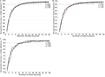
The data collected in the first experiment were used for offline source selection. The effect of increasing the number of selected data sources on the intent recognition accuracy in static states was similar among the three tested algorithms (SFS, SBS, and mRMR) (Figure 3): when the number of applied data sources increased, the classification accuracy increased dramatically and gradually plateaued. When 95% accuracy (indicated by a red dashed line in Figure 3) was chosen as the criterion to select the informative set of data source for all studied selection methods, the number of selected sources was 9, 11, 10, and 10 for TF01-TF04, respectively.
Figure 3. Accuracy of intent recognition in static states when the number of selected data sources increased. The applied source selection methods were (A) sequential forward selection (SFS), (B) sequential backward selection (SBS), and (C) minimum-redundancy–maximum-relevance (mRMR).
Table 2.
The Sources Selected for Four Recruited TF Subjects (TF01-TF04)
TF01 TF02 TF03 TF04
SFS SBS mRMR SFS SBS mRMR SFS SBS mRMR SFS SBS mRMR
Fz VM TFL My BFL TFL VL VM VL E2* Mx SEM
BFL BFS RF Mx Mx RF Mx TFL RF E1* TFL ADM
My ADM My VL VL TAcc_y SEM Fy VM Mx E2* E2*
RF My VM Fz TFL SEM BFS Mx TFL TAcc_y E1* Fz
VL RF BFL BFL BFS ADM Fz BFL Fy VL Fz TFL
TFL BFL Fz ADM Fy VM ADM SEM SEM Fz VL E1*
Mz Fz TAcc_y BFS RF BFS TFL VL ADM ADM Mz TAcc_y
VM TAcc_y Mx TFL ADM VL Fy ADM Mx TFL Fy VL
TAcc_y TFL Fy TAcc_y Fz Fz VM Fz Fz SEM SEM VM
SEM TAcc_y Mx RF TAcc_z BFS Mz ADM Mx
TAcc_z SEM BFL
Additionally, we compared the execution time of three different source selection algorithms. mRMR required the shortest execution time (an average of 84 seconds over the four subjects), while SBS was the most time-consuming algorithm (requiring an average of 1978 seconds). SFS took approximately 383 seconds for data source selection. Since mRMR
was the most computationally efficient algorithm and yielded similar performance to the other two searching algorithms (Table 2 and Figure 3), the sources selected by mRMR were used in the second experiment for real-time mode recognition in order to evaluate the robustness of the selected data sources across days.
2.4.2 Real-time Performance with and without Data Sources Selection
The performance of the intent-recognition interface in static states was compared with and without data source reduction (Figure 4). The accuracy decreased to approximately 95% when the data sources selected by mRMR were used (gray and white bars in Figure 4), compared to around 98% accuracy derived from all data sources (the black bars in Figure 4). This was to be expected, as 95% accuracy was used as the threshold in one of the searching criteria. Importantly, the system produced stable performance in the static states by using the same data sources selected by mRMR across days, which implied that the selected data sources robustly captured important information for accurate intent recognition.
When all data sources were used for online testing (in the first experimental day), the
experiment), the online processing time ranged from 21.3ms to 28.8ms for the four subjects, which would result in more frequent decision-making.
Figure 4. Intent recognition accuracy in static states. The black bars were derived from the real-time decisions in the first experiment when all the data sources were used. The
gray bars were computed offline based on the data in the first experiment, but with a reduced number of data sources selected by mRMR. The white bars denote the real-time results derived from the second experiment when the same data sources as used for
Table 3.
Average Task Transition Prediction Time across Subjects in the First and Second Real-time Experiments
Prediction Time for Different Task Transitions (ms) W SA SA W W SD SD W W RA RA W W RD RD W W ST ST W S ST ST S All Sources (Real-time results in the
experiment 1) 120.8 114.5 127.1 115.4 107.7 104.4 105.9 116.5 86.2 118.4 88.0 324.
4 Selected Sources
(Real-time results in the experiment 2)
119.3 112.4 115.9 111.9 118.3 113.4 102.4 134.7 96.4 124.7 94.2 305. 8
2.5 Discussion
In this study we aimed to investigate the usefulness of each data source used for user intent recognition, and determine an informative set of data sources for efficient real-time intent-recognition for the control of artificial legs. The offline source-selection analysis showed that when the number of data sources was reduced from 26 to approximately 10, the interface was still able to accurately recognize the subject’s intents (above 95% accuracy in
static states) without missing additional mode transitions. These results indicate that not all of the studied data sources carried important information for intent recognition and input redundancy existed in the initial design of fusion-based interface. Therefore, reduction of system redundancy is necessary to improve the efficiency of the design for its eventual clinical use for artificial legs. At the hardware level, removing sources that capture less important or redundant information can simplify the design of the instrumented prosthetic leg, I/O circuits, wiring, and embedded system. At the software level, reducing the number of data sources decreases the computational complexity of the intent-recognition algorithm. For example, in this study we showed that the computational speed for recognizing intents with a reduced number of data sources was almost 1.9 times faster than that when using all data sources.
The results of this study showed that all three methods selected similar data sources when at least 95% accuracy for recognizing user intent was required. However, the mRMR method is suggested for future clinical application because (1) it was much more computationally efficient than the other two searching methods; (2) the mRMR algorithm can be used regardless of the type and structure of the classifier; while SFS and SBS involve the direct goal of maximizing the classification accuracy of one particular classifier. Furthermore, the data sources selected by mRMR were robust over time. Similar performance was observed across experimental days when the mRMR-selected sources were used to classify task modes.
Another important contribution of this study was the real-time PC implementation of our previously designed intent-recognition interface. Unlike previous design, in which we used offline cross validation to evaluate the interface [15], this study included a system-training protocol for quick calibration and real-time algorithm for online system testing. The real-time interface could make a decision every 50ms and produced high accuracy for intent recognition and task transition prediction, similar to the results of the offline analysis [15]. These results imply the soundness of our designed training protocol and real-time intent-recognition algorithm; these designs can be used for the future embedded implementation of an intent recognition interface for artificial legs.
simply choose the optimization criteria and run the program for quick sensor placement guidance. In addition, our real-time mode-recognition algorithm can be directly implemented in the embedded control units in prosthetic knees. Nevertheless, several study limitations were also identified. First, the evaluation of the system was done in the laboratory, due to the limitations of our experimental setup. It will be important to further test our system in more realistic environments. In addition, the reported execution speed for locomotion mode recognition was not the true online processing speed for CPU implementation. This is because we did not ignore background programs in the PC, and MATLAB does not allow multi-threaded programs. The execution speed should be faster when a powerful digital signal processor is used. Furthermore, this study fixed the optimization criteria to 95% classification accuracy. Further studies are needed to justify whether or not this criterion is sufficient for safe prosthesis control. Finally, it was noteworthy that the suggestion of sub-optimal sensor configuration for volitional control of power artificial legs was made only based on the results from the recruited subjects. Customization of sensor configuration for each individual user is desired in the future clinical application.
2.6 Conclusion
In this study, we analyzed the usefulness of different data sources for user intent recognition and identified an informative set of data sources for volitional control of prosthetic legs. First, our previously designed interface based on neuromuscular-mechanical
accurate recognition of the user’s intended task by using three source selection algorithms.
The real-time performance of the intent-recognition algorithm with and without source selection was evaluated and compared on four patients with TF amputations on different experimental days. Based on the study results, we suggested a protocol for determining the informative data sources and sensor configurations for future development of volitional control of powered artificial legs.
REFERENCES
[1] K. Ziegler-Graham, E. J. MacKenzie, P. L. Ephraim, T. G. Travison, and R. Brookmeyer, “Estimating the prevalence of limb loss in the United States: 2005 to 2050,” Arch Phys Med Rehabil, vol. 89, no. 3, pp. 422-9, Mar, 2008.
[2] T. M. Cutson, and D. R. Bongiorni, “Rehabilitation of the older lower limb amputee: a brief review,” J Am Geriatr Soc, vol. 44, no. 11, pp. 1388-93, Nov, 1996.
[3] D. D. Fletcher, K. L. Andrews, J. W. Hallett, Jr., M. A. Butters, C. M. Rowland, and S. J. Jacobsen, “Trends in rehabilitation after amputation for geriatric patients with vascular disease: implications for future health resource allocation,” Arch Phys Med
Rehabil, vol. 83, no. 10, pp. 1389-93, Oct, 2002.
[4] F. Sup, A. Bohara, and M. Goldfarb, “Design and Control of a Powered Transfemoral Prosthesis,” Int J Rob Res, vol. 27, no. 2, pp. 263-273, Feb 1, 2008.
[6] E. C. Martinez-Villalpando, and H. Herr, “Agonist-antagonist active knee prosthesis: a preliminary study in level-ground walking,” J Rehabil Res Dev, vol. 46, no. 3, pp. 361-73, 2009.
[7] I. Otto Bock Orthopedic Industry, Manual for the 3c100 Otto Bock C-LEG, Duderstadt, Germany, 1998.
[8] OSSUR, The POWER KNEE, The POWER KNEE ed.:
http://bionics.ossur.com/Products/POWER-KNEE/SENSE.
[9] S. Bedard, and P. Roy, Actuated leg prosthesis for above-knee amputees, U.S. Patent 7 314 490, 2003.
[10] H. A. Varol, F. Sup, and M. Goldfarb, “Multiclass real-time intent recognition of a powered lower limb prosthesis,” IEEE Trans Biomed Eng, vol. 57, no. 3, pp. 542-51, Mar, 2010.
[11] L. J. Hargrove, A. M. Simon, R. D. Lipschutz, S. B. Finucane, and T. A. Kuiken, “Real-time myoelectric control of knee and ankle motions for transfemoral amputees,” JAMA, vol. 305, no. 15, pp. 1542-1544, 2011.
[12] K. H. Ha, H. A. Varol, and M. Goldfarb, “Volitional control of a prosthetic knee using surface electromyography,” Biomedical Engineering, IEEE Transactions on,
vol. 58, no. 1, pp. 144-151, 2011.
[13] H. Huang, T. A. Kuiken, and R. D. Lipschutz, “A strategy for identifying locomotion modes using surface electromyography,” IEEE Trans Biomed Eng, vol. 56, no. 1, pp.
[14] W. Flowers, and R. Mann, “An electrohydraulic knee-torque controller for a prosthesis simulator,” Journal of biomechanical engineering, vol. 99, no. 1, pp. 3-8,
1977.
[15] H. Huang, F. Zhang, L. Hargrove, Z. Dou, D. Rogers, and K. Englehart, “Continuous Locomotion Mode Identification for Prosthetic Legs based on Neuromuscular-Mechanical Fusion,” IEEE Trans Biomed Eng, Jul 14, 2011.
[16] S. A. Hale, “Analysis of the swing phase dynamics and muscular effort of the above-knee amputee for varying prosthetic shank loads,” Prosthet Orthot Int, vol. 14, no. 3,
pp. 125-35, Dec, 1990.
[17] F. Zhang, Z. Dou, M. Nunnery, and H. Huang, “Real-time implementation of an intent recognition system for artificial legs,” Conf Proc IEEE Eng Med Biol Soc, vol.
2011, pp. 2997-3000, 2011.
[18] B. Hudgins, P. Parker, and R. N. Scott, “A new strategy for multifunction myoelectric control,” IEEE Trans Biomed Eng, vol. 40, no. 1, pp. 82-94, Jan, 1993.
[19] D. Anguita, A. Boni, and S. Ridella, “A digital architecture for support vector machines: Theory, algorithm, and FPGA implementation,” Ieee Transactions on
Neural Networks, vol. 14, no. 5, pp. 993-1009, Sep, 2003.
[20] B. J. Frey, Graphical models for machine learning and digital communication, Cambridge, Mass: The MIT Press, 1998.
[22] J. Liu, S. Ranka, and T. Kahveci, “Classification and feature selection algorithms for multi-class CGH data,” Bioinformatics, vol. 24, no. 13, pp. i86-95, Jul 1, 2008.
[23] T. R. Golub, D. K. Slonim, P. Tamayo, C. Huard, M. Gaasenbeek, J. P. Mesirov, H. Coller, M. L. Loh, J. R. Downing, M. A. Caligiuri, C. D. Bloomfield, and E. S. Lander, “Molecular classification of cancer: class discovery and class prediction by gene expression monitoring,” Science, vol. 286, no. 5439, pp. 531-7, Oct 15, 1999.
[24] C. Ding, and H. Peng, “Minimum redundancy feature selection from microarray gene expression data,” J Bioinform Comput Biol, vol. 3, no. 2, pp. 185-205, Apr, 2005.
[25] F. Model, P. Adorjan, A. Olek, and C. Piepenbrock, “Feature selection for DNA methylation based cancer classification,” Bioinformatics, vol. 17 Suppl 1, pp.
S157-64, 2001.
CHAPTER 3:
Effects of Locomotion Mode Recognition Errors on Volitional
Control of Powered Above-Knee Prostheses
Fan Zhang, Ming Liu, He Huang
As published in IEEE Transactions on Neural Systems and Rehabilitation
Engineering
3.1 Abstract
happened and (2) the amount of mechanical work change applied on the powered knee caused by the errors. Based on the study results, "critical errors" were defined and suggested as a new index to evaluate locomotion mode recognition algorithms for artificial legs. The outcome of this study might aid the future design of volitionally-controlled powered prosthetic legs that are reliable and safe for practice.
3.2 Introduction
Rapid advancement of powered artificial legs has attracted increasing attention in recent years [1-5]. The advantage of powered artificial legs over traditional passive devices is that they can enable lower limb amputees to more easily and efficiently perform a variety of activities, such as stair climbing. Powered artificial legs usually employ a finite-state machine (FSM) to control the joint impedance or joint position [3, 4]. In such a control scheme, the joint impedance or position varies across gait phases for cyclic locomotion tasks or movement state for non-cyclic tasks. The control of a powered prosthesis also depends on the user’s intent regarding locomotion modes. This is because the required dynamics and
kinematics of prosthetic limbs are different among different locomotion modes (e.g. level-ground walking and stair ascent/descent). Therefore, in order to enable smooth locomotion mode transition in prosthesis users, it is essential to integrate locomotion mode recognition with FSM-based intrinsic control for volitional operation of powered lower limb prostheses.
were used to modulate the impedance control of a powered AK prosthesis. The reported method can identify gait initiations, terminations, and transitions between sitting and standing of one AK amputee with 100% accuracy rate and 500ms system delay. Another approach is to interpret the user’s intent regarding locomotion mode by monitoring the neuromuscular control activity measured from the residual muscles or reinnervated muscles. Au et al. [5] used electromyography (EMG) signals from residual shank muscles to identify two locomotion modes (i.e. level ground walking and stair descent) of one below-knee amputee. All tested mode transitions were accurately identified to manipulate a powered foot-ankle prosthesis. Huang et al. [7] proposed a phase-dependent EMG pattern recognition strategy that can identify seven locomotion modes with approximately 90% accuracy rate as demonstrated with two above-knee (AK) amputees. To better improve the accuracy in recognizing the user's locomotion mode, our group made use of both EMG signals and mechanical feedback from the prosthesis to classify the user's locomotion mode [8]. Such a method based on neuromuscular-mechanical fusion was evaluated on above-knee amputees online [9] and showed improved performance compared to the locomotion mode recognition method based on EMG or mechanical signals only. A recent study [10] reported a successful case of using EMG signals from targeted reinnervated muscles and mechanical measurements from a prosthesis to interpret an amputee’s intent and control a powered
above-knee prosthesis.
trigger the erroneous operation of prostheses, disturb the user’s task performance, or even
cause posture instability or the user's falls. These volitional control errors may significantly affect the confident and safe use of powered prostheses in lower limb amputees. Therefore, identification and elimination of the negative effects of these user intent recognition errors on the control of powered artificial legs is imperative. To the best of our knowledge, a very limited number of studies have reported the effects of locomotion mode recognition errors on volitional control of lower limb prostheses. Varol et al. [6] reported that a user intent recognition error that falsely classified the standing mode as level ground walking mode did not affect the prosthesis control and the user's performance. However, only one type of error was reported, and no systematic investigation was provided. In a recent study [10], intent recognition errors were observed to cause disturbance of the subject’s gait stability to varying degrees.
The results of this study could completely change the way for evaluating locomotion mode recognition systems for powered AK prostheses and propel the future design of volitionally-controlled powered artificial legs that are functional and safe-to-use.
3.3 Methods
3.3.1 Design and Control of a Powered Above-Knee Prosthesis
high-level controller for locomotion mode recognition and a low-level intrinsic controller, as demonstrated in Figure 1. In the high level controller, a locomotion mode recognition system was designed to interpret the user’s intended activities (e.g. level ground walking, ramp
ascent, and ramp descent in this study). The system monitored the EMG signals measured from user’s residual limb muscles and mechanical measurements from the prosthetic pylon, recognized user’s intent, and then switched the control mode in the low-level controller. The
low-level intrinsic control is based on the mechanical feedback measured from the prosthesis only. It consists of a finite-state machine (FSM) and impedance controller. Impedance control has been widely used for prosthetic legs [3, 6, 12] because it is believed that humans control the stiffness of leg muscles while walking [13, 14]. The goal of the intrinsic control is to ensure that the prosthetic knee acts as a passive spring-damper-system with predefined impedance (i.e. stiffness k, damping coefficient c, and equilibrium position θk) that matches
the biological knee impedance during walking [12]. To achieve this goal, five states were defined, each of which correspond to one gait phase. The defined five states were initial double support (IDS), single support (SS), terminal double support (TDS), swing flexion (SWF), and swing extension (SWE) (Figure 1). The state transitions are triggered by intrinsic measurements, such as ground reaction force (F ), knee angle (), and angular velocity ().
Once a state i was selected, the desired knee impedance [
i
k ,ci ,ki] corresponding to this state
3.3.2 Investigated Locomotion Mode Recognition Errors
In this study, we selected several types of mode recognition errors which were often observed in our previously developed mode recognition system for artificial legs. Locomotion mode recognition based on neuromuscular-mechanical fusion has been designed and evaluated on AK amputee patients in real time in a previous study. Despite high accuracy rate for mode recognition reported, occasional errors were still observed. Table 1 listed the confusion matrix derived from our designed mode recognition algorithm tested online on four AK amputees [9]. The diagonal numbers represented the accuracy rate (in percent) for recognizing individual locomotion modes; the non-diagonal elements denoted the misclassification rate (in percent) between two modes. The interface was used to recognize five cyclic locomotion modes (e.g. level-ground walking, stair ascent/descent, and ramp ascent/descent) and two non-cyclic locomotion modes (sitting and standing). The table shows that most of the confusion errors happened among the tasks of level-ground walking, ramp ascent, and ramp descent (indicated by gray areas in Table 1). This observation was also consistent with the results from a recent study [15] in which an intent recognition system was evaluated on four AK amputees wearing a powered knee and ankle prosthesis. Their results also indicated that ambulating on ramps had a significantly (P<0.01) higher error rate than walking on staircases. Therefore, based on the knowledge from previous studies, four types of frequently occurring mode recognition errors were considered in this study: level-ground walking misclassified as ramp ascent (W→RA) or ramp descent (W→RD), ramp ascent
level-ground walking (RD→W). Since immediately transitions between ramp ascent and descent
rarely happen, the errors for recognizing between these two modes (i.e. RA→RD and RD→RA) were not considered. Besides the types of errors, the error durations and occurred
timing were also investigated. Based on the observation in our previous study, it has been found that the continuous error decisions generally lasted no more than 300ms. Therefore, in this study, four different types of errors (W→RA, W→RD, RA→W, and RD→W) with
different durations (100, 200, or 300ms) at all defined phases (IDS, SS, TDS, SWF, or SWE) were investigated.
To systematically investigate the effects of selected mode recognition errors, a mode recognition simulator was used to replace the high-level control shown in Figure 1. The simulator directly sent the user’s locomotion mode to low-level intrinsic control; no mode
Table 1.
Confusion Matrix for Locomotion Mode Recognition Derived Based on Neuromuscular-mechanical Fusion Strategy
(%)
Targeted Modes
W SA SD RA RD ST S
Esti
mate
d
Mode
s
W 96.11 0.47 0.45 4.81 4.13 0.00 0.00
SA 0.12 98.39 0.55 0.39 0.00 0.09 0.00
SD 0.19 0.39 98.32 0.00 0.20 0.00 0.00
RA 1.68 0.42 0.00 93.78 1.21 0.00 0.00
RD 1.76 0.32 0.52 1.02 94.47 0.00 0.00
ST 0.14 0.00 0.16 0.00 0.00 99.91 0.00
S 0.00 0.00 0.00 0.00 0.00 0.00 100.00
3.3.3 Participants and Measurements
This study was conducted with the approval of Institutional Review Board (IRB) and with informed consent of all the subjects. Five able-bodied subjects (AB01-05) and two patients with unilateral above-knee amputations (AK01-02) were recruited in this study. The recruited AB subjects were all male and free from orthopedic or neurological pathologies. The average age of the AB subjects was 28.6 (±5.3) years. The average height was 181.6 (±4.8) cm. The average weight was 82.3 (±11.7) kg. AK01 (age: 60 years; height: 175.3 cm; weight: 75.8 kg) was a male amputee with 33-year post-amputation; AK02 (age: 41 years; height: 162.2 cm; weight: 65.7 kg) was a female amputee with 32-year post-amputation. They both were regular passive prostheses users. During the experiments, the AK subjects wore suction prosthetic sockets. For AB subjects, a special designed bent-knee adaptor was used so that they can walk with the powered prosthesis.
3.3.4 Experimental Protocol
Before the experiments, all the subjects were trained to walk with the designed powered prosthesis. Each subject received at least 10-hour gait and balance training sessions, led by a physical therapist. This training was necessary because the powered device redefined the gait dynamics in the recruited subjects. Amputees must re-adapt to the powered device. The prosthesis alignment and desired joint impedance parameters for each studied locomotion mode (including level-ground walking, ramp ascent and descent) were calibrated for each individual subject by a prosthetist and an experienced experimenter. All the subjects were able to adapt to the powered prosthesis and generate stable and consistent gait patterns when performing each assigned locomotion mode.
3.3.5 Evaluation of Gait Stability
The effects of mode recognition errors on the prosthesis user’s gait stability were evaluated both subjectively and objectively. A four-scale questionnaire (score 0-3) was designed to subjectively evaluate the gait stability of the subjects when the errors occurred. Table II listed the designed question and the descriptions for each scale of answer. After each trial, the subject was asked to report the score regarding the gait stability according to Table 2. For the same error, the subjective result was obtained by averaging the scores across multiple tests. If the averaged score was greater than 1, the error was considered to cause subjective feeling of gait instability.
The gait stability was also evaluated objectively by monitoring full-body angular momentum. Biomechanical investigations [16, 17] have demonstrated that the conservation of total angular momentum about the body’s center of mass (COM) is highly regulated during human’s ambulation. The full-body angular momentum has been used for the analysis