ABSTRACT
KULKARNI, KSHITIJ DWARKADHISH. UVM-based Verification Suite for a Cache. (Under the direction of Dr. W. Rhett Davis.)
This thesis describes the work done towards creating a verification environment for the
data cache in H3 microprocessor using Universal Verification Methodology (UVM). UVM is
a Accelera standard and combines features from Open Verification Methodology (OVM)
and Verification Methodology Manual (VMM).
The cache was verified for functional behavior in[4]. In this thesis, we have concentrated
on defining a comprehensive coverage metric and developing stimulus to achieve this
coverage.
In the process of developing a verification suite for the cache, a simple testbench using SystemVerilog object-oriented programming (OOP) principles was converted to UVM. The
UVM features used to do this and the steps used in modifying the testbench are documented.
This serves to act as a guide to convert a simple testbench to a UVM compliant testbench.
This exercise also helped in understanding the many advantages of using a well-defined
methodology like UVM for developing verification suites over using only SystemVerilog
constructs. The UVM features are compared against the simple OOP-testbench in terms of
factors like the ease of developing the testbench structure, ease of developing new tests,
reusability, etc.
For a target reader that may use the developed UVM-based verification suite to verify the cache, we’ve added a chapter describing the process of adding new tests to the verification
suite.
© Copyright 2016 by Kshitij Dwarkadhish Kulkarni
UVM-based Verification Suite for a Cache
by
Kshitij Dwarkadhish Kulkarni
A thesis submitted to the Graduate Faculty of North Carolina State University
in partial fulfillment of the requirements for the Degree of
Master of Science
Computer Engineering
Raleigh, North Carolina
2016
APPROVED BY:
Dr. Eric Rotenberg Dr. Paul D. Franzon
DEDICATION
Dedicated to my mother who has taken me through many rough times without me feeling
BIOGRAPHY
Kshitij Dwarkadhish Kulkarni earned his Bachelor Of Technology in Electronics Engineering
from Walchand College of Engineering, Sangli in 2011. He worked for White Rodges division
of the Emerson Electric Company from 2011 to 2014.
He joined NC State University in Fall 2014 to pursue Master Of Science in Computer
ACKNOWLEDGEMENTS
Every work is a result of contributions from many people. I would like to take this
op-portunity to express my gratitude towards everyone who directly or indirectly helped me
accomplish this goal.
I would like to thank my advisor Dr. W. Rhett Davis for encouraging me to take up this
idea for my thesis. His clear directions about the goals of the project helped me stay focused.
Otherwise I would’ve been, in his own words, "a deer stuck in headlights". His advice for writing the thesis made a difficult task simple. I’m grateful that he helped me get funding
during my effort. I would also like to thank my committee members. Dr. Eric Rotenberg
for making Computer Architecture interesting and Dr. Paul Franzon for his words "design
before coding" which I always use as a mantra. I would like to thank Mentor Graphics for
funding my efforts.
I would like to thank my other teachers at NC State, Dr. Huiyang Zhou for helping me
generate an interest in Computer Architecture, Dr. Brian Floyd for helping me get over my
phobia of transistors.
I would like to thank Rangeen Basu Roy Chowdhary and Vinesh Shrinivasan whose prior efforts I am working on. They were always there to help me understand the little details.
Verification is a constant dialog between the verification engineer and the design engineer.
I am grateful that Rangeen and Vinesh humored all my questions.
I would like to thank my teachers in India Dr. Narayan Marathe, Dr. Shaila Subbaraman,
Dr. Y. V. Joshi, Dr. Ganesh Bhokare and Dr. M. Prakash for feeding my curiosity.
My family members, Dr. Geeta Kulkarni, Parikshit and Shrawni and all my extended
family in India who have always wished the best for me. I would like to thank my many
friends in India Neeraj, Yogesh, Sandesh, Aonkar, Swapnil who made themselves available
for me whenever I needed them. I would like to thank Sumedha for being the sounding board for my complaints against everyone.
I would like to thank my family in Raleigh: my room-mates Anish, Omkar, Rohit for
bearing with me when I was working on my thesis. Thanks Swati, Reshma, Chaitanya,
Sourabh, Rutuja, Salil, Mihir, Pranit for being great friends and support.
Finally, I know he won’t read this, but I would like to thank Louis C.K., comedian/
TABLE OF CONTENTS
LIST OF TABLES . . . viii
LIST OF FIGURES. . . ix
Chapter 1 INTRODUCTION . . . 1
1.1 Introduction . . . 1
1.2 Outline . . . 3
Chapter 2 Cache Specification . . . 4
2.1 Cache Specification . . . 4
2.2 Store Features . . . 5
2.2.1 Store Interface signals . . . 5
2.2.2 Store Requests . . . 6
2.2.3 Store Buffer . . . 7
2.3 Load Features . . . 8
2.3.1 Load interface to and from the cache . . . 8
2.3.2 Load request and responses: . . . 9
2.3.3 Load sizes: . . . 9
2.3.4 Non-blocking interfaces: . . . 10
2.3.5 Store-load forwarding: . . . 10
2.3.6 Cache fill request and response from lower hierarchy: . . . 11
2.3.7 Miss Status Handling Register (MSHR): . . . 11
2.3.8 MSHR delays: . . . 12
2.3.9 MSHR data: . . . 12
2.4 Invalidation requests: . . . 13
2.5 Scratch mode: . . . 13
2.5.1 Scratch-mode interface signals: . . . 14
2.5.2 Load interface for scratch-mode: . . . 14
2.5.3 Store interface for scratch-mode: . . . 15
Chapter 3 OOP-Testbench . . . 16
3.1 Interface: . . . 17
3.2 Transactor: . . . 18
3.3 Generating stimulus. tester: . . . 20
3.4 Applying stimulus. Driver: . . . 21
3.5 Tester to driver interface: . . . 23
3.6 Monitoring the responses from the DUT. Monitor: . . . 23
3.7 Generating ideal responses. Scoreboard: . . . 25
3.9 Gathering coverage information. Coverage: . . . 26
3.10 Testbench class: . . . 27
3.11 Putting it all together. top module: . . . 28
3.12 Comments: . . . 28
Chapter 4 UVM-based Verification Suite . . . 30
4.1 UVM features . . . 31
4.1.1 uvm_component and uvm_object . . . 31
4.1.2 UVM factory . . . 31
4.1.3 UVM configuration database: . . . 33
4.1.4 UVM phases . . . 34
4.1.5 Raising objections . . . 36
4.1.6 Observer design pattern[3]. . . 37
4.1.7 uvm_sequence_item: . . . 41
4.1.8 uvm_driver: . . . 41
4.1.9 uvm_sequencer: . . . 42
4.2 Creating UVM testbench . . . 42
4.2.1 Step 1: Changing Interface to BFM[3] . . . 42
4.2.2 Step 2: Change all data packets to uvm_transactions: . . . 44
4.2.3 Step 3: Modify Monitor to uvm_component . . . 44
4.2.4 Step 4: Modify the Checker to uvm_component: . . . 46
4.2.5 Step 5: Modify the Scoreboard: . . . 47
4.2.6 Step 6: Modify the Coverage: . . . 49
4.2.7 Step 7: Modify core_cache_if: . . . 50
4.2.8 Step 8: Modify the Driver: . . . 51
4.2.9 Step 9: Create dcache_agent: . . . 53
4.2.10 Step 10: Create an env class: . . . 55
4.2.11 Step 11: Create base_test class: . . . 56
4.2.12 Step 12: Create the top module: . . . 57
4.3 Comments: . . . 58
Chapter 5 Adding a test . . . 59
5.1 base_test class: . . . 60
5.2 uvm_sequence_item: . . . 62
5.3 Creating uvm_sequence: . . . 62
5.4 Setting the value of the sequence_items: . . . 65
5.5 Creating new tests . . . 67
5.6 One-time compilation of the new sequence and the test: . . . 69
5.7 Running a test, switching between tests: . . . 72
5.8 Steps for adding a test: . . . 72
6.1 Coverage: . . . 74
6.1.1 Load coverage: . . . 74
6.1.2 Store coverage: . . . 76
6.1.3 MSHR coverage: . . . 77
6.1.4 State-space coverage: . . . 78
6.1.5 Delays: . . . 79
6.1.6 Scratch mode coverage: . . . 80
6.2 Stimulus generation: . . . 81
6.2.1 Line test. Load, store and parallel: . . . 81
6.2.2 Stride test: . . . 83
6.2.3 MSHR data test: . . . 85
6.2.4 Stress test: . . . 86
6.2.5 Random stimulus: . . . 87
6.2.6 Scratch mode test: . . . 88
Chapter 7 Results . . . 89
7.1 Comparing the two testbenches . . . 90
7.1.1 Adding a new test: . . . 90
7.1.2 Changing a feature in the scoreboard: . . . 92
7.1.3 Comments . . . 92
7.2 Bugs revealed by the verification suite . . . 92
7.2.1 Inconsistency in load-forwarding: . . . 92
7.2.2 Load response behavior on partial hit in store buffer: . . . 93
7.2.3 Load request forwarded twice for the same load address . . . 94
7.2.4 Store forwarding size . . . 94
7.3 Coverage Achieved . . . 95
Chapter 8 Conclusion . . . 96
LIST OF TABLES
Table2.1 Core-to-Cache Store Interface Signals . . . 5
Table2.2 Store Sizes . . . 5
Table2.3 Cache-to-memory. Store interface signals . . . 6
Table2.4 Core-to-cache. Load interface signals . . . 8
Table2.5 Load sizes . . . 8
Table2.6 mem2cache interface signals . . . 9
Table2.7 Scratch Mode Interface signals . . . 14
Table5.1 core_cache_if class details . . . 65
LIST OF FIGURES
Figure3.1 OOP-Testbench Structure . . . 18
Figure3.2 Transactor . . . 19
Figure3.3 Tester run() task . . . 21
Figure3.4 Driver run() task . . . 22
Figure3.5 core_cache_if class . . . 24
Figure3.6 Monitor run() task . . . 25
Figure3.7 Testbench run() task . . . 27
Figure4.1 UVM Factory . . . 32
Figure4.2 UVM Factory in action . . . 32
Figure4.3 Registering Object with Factory . . . 33
Figure4.4 create() function to instantiate objects . . . 33
Figure4.5 Storing in uvm_config_db . . . 34
Figure4.6 Retrieving from uvm_config_db . . . 34
Figure4.7 constructor and build_phase . . . 36
Figure4.8 Raising Objections . . . 37
Figure4.9 Connections using multiple mailboxes . . . 38
Figure4.10 Observer Design Pattern connections . . . 39
Figure4.11 Register Monitor with Factory . . . 44
Figure4.12 UVM Analysis Ports in Monitor . . . 45
Figure4.13 Monitor build_phase() . . . 45
Figure4.14 Monitor . . . 46
Figure4.15 uvm_tlm_analysis_fifos in Checker . . . 46
Figure4.16 Checker build_phase() . . . 47
Figure4.17 Checker run_phase() . . . 47
Figure4.18 Checker . . . 48
Figure4.19 Register Scoreboard with Factory . . . 48
Figure4.20 Scoreboard . . . 49
Figure4.21 Coverage . . . 50
Figure4.22 Extend core_cache_if from uvm_sequence_item . . . 51
Figure4.23 Driver class definition . . . 51
Figure4.24 Driver run_phase() . . . 52
Figure4.25 Driver . . . 53
Figure4.26 Agent build_phase() . . . 54
Figure4.27 Agent run_phase() . . . 54
Figure4.28 Agent . . . 55
Figure4.29 Env . . . 56
Figure5.1 base_test: Define env and sequencer . . . 60
Figure5.2 base_test: build_phase . . . 60
Figure5.3 base_test: end_of_elaboration_phase . . . 61
Figure5.4 base_test sequencer connections . . . 61
Figure5.5 sequence class definition . . . 62
Figure5.6 body() task example . . . 63
Figure5.7 Sequences using other sequences . . . 64
Figure5.8 run_phase() of a test . . . 68
Figure5.9 Multiple sequences in parallel . . . 69
Figure5.10 UVM_TEST . . . 70
Figure5.11 dcache_tb_package . . . 71
Figure7.1 Load request to same line, different tag. Request Forwarded . . . 93
CHAPTER
1
INTRODUCTION
1.1
Introduction
Digital systems are getting larger in size (in terms of number of transistors) and complexity.
Multi-core processors are now much more common and the design complexity involved
in them increases the verification effort significantly. Multiple cores add the additional
design and verification effort of cache-coherence to them. Constrainted-random tests are necessary to verify any design of this complexity. Moreover since the turnaround time
for new designs is expected to reduce, re-usability of verification environments is critical.
Industry bodies, like Accellera, have developed many methodologies that help in developing
re-usable testbenches. We’ll like to explore the Universal Verification Methodology in this
thesis. UVM is an extensive base-class library to develop verification environments. It is
now an IEEE standard for verification.
1.1. INTRODUCTION CHAPTER 1. INTRODUCTION
cores, a one-wide core and a two-wide core. The cache designed for the processor has a
simple invalidation-only coherence protocol for maintaining coherence between the cores.
It also has cache-core decoupling for ease of thread-migration[4]. Our focus will be exploring
the process of verification of this cache using the Universal Verification Methodology (UVM).
More about UVM: it is a base-class library over the existing SystemVerilog verification
language. It was standardized by Accelera through efforts from EDA vendors and contri-butions from established methodologies like Open Verification Methodology (OVM) and
Verification Methodology Manual (VMM)[2][5]. The UVM features include methods of
con-necting different components of a testbench with clearly defined interfaces which helps
in maintaining the testbench over multiple iterations of a project. The idea is that while
the internals of each components change, the interfaces shouldn’t. Hence the structure
becomes easier to modify and maintain.
This cache was previously verified for functional purposes[4]. This thesis describes
the verification of the cache to cover all the features of the cache, some of which may
not have been covered during functional testing. We define a coverage goal and try to achieve it by defining stimulus. Before doing that we need to document the specifications
of the cache so that we can define the coverage better. In satisfying the above goal, we
hope to explore the features of UVM and document the various advantages that we gain by
doing so. To do that we need to have a baseline testbench to compare it to. We start with
a testbench developed using the Object Oriented features of the SystemVerilog language.
This testbench is very similar to the one developed for ECE745: ASIC Verification class
taught at NC State University. Then we explain the procedure used to convert this testbench
to a UVM-compliant testbench.
Summarizing our major goals:
1. Documenting the specification of the H3 cache.
2. Developing a baseline SystemVerilog based Object-Oriented testbench (OOP-testbench)
for the cache.
3. Converting the OOP-testbench to a UVM-based verification-suite for the cache.
4. Documenting the process of modifying the OOP-testbench developed in
1.2. OUTLINE CHAPTER 1. INTRODUCTION
5. Defining the coverage metric for the cache.
6. Exploring the advantages that we gained by using the UVM over the OOP-testbench.
1.2
Outline
The document is divided into 8 chapters. In chapter 2, we formally describe the cache
features and specifications against which we will be verifying the cache. Chapter 3 and 4
explore the structure of the testbench. In chapter 3 we look at a testbench for the cache
de-veloped using basic Object-Oriented Programming principles of SystemVerilog. In chapter
4 we will be looking at the UVM features and will be using them by modifying our existing
OOP-testbench. In this way, we not only hope that the reader will get an idea of UVM,
but also will get a step-by-step guideline of how to convert a OOP-testbench to be UVM
compatible. In chapter 5 we explain how to add new tests to the UVM verification suite.
This is targeted towards users who will be using the verification-suite to verify the cache in future projects. In chapter 6, we concentrate on the coverage metric for the verification
effort and the stimulus used to achieve the coverage. Chapter 7 discusses the results of the
CHAPTER
2
CACHE SPECIFICATION
Before discussing the testbench and the coverage metric, we spend some time looking at
the specifications of the cache. This will give us better understanding of the features and
the way they interact. Internal details of the design-under-test (DUT) functionality are also
important when measuring coverage. For example, if the DUT has a state machine, we need
to ensure that we are traversing all the valid transitions of the state machine.
2.1
Cache Specification
The cache is a direct-mapped, write-through write-not-allocate cache. The line-size, num-ber of lines are configurable and the verification suite keeps them configurable. But for the
cache used in H3 processor:
1. Cache-size: 2 kB
2.2. STORE FEATURES CHAPTER 2. CACHE SPECIFICATION
2.2
Store Features
2.2.1
Store Interface signals
• Following are the store interface signals between the cache and the upper hierarchy.
Each signal’s name ends with the direction it has been indicated.
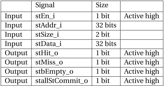
Table 2.1Core-to-Cache Store Interface Signals
Signal Size
Input stEn_i 1 bit Active high Input stAddr_i 32 bits
Input stSize_i 2 bit Input stData_i 32 bits
Output stHit_o 1 bit Active high Output stMiss_o 1 bit Active high Output stbEmpty_o 1 bit Active high Output stallStCommit_o 1 bit Active high
• The different sizes that the store can have are shown in table below.
Table 2.2Store Sizes
Value Size
00 Byte 01 Half-Word 01 Word
• The signals in the store interface between the cache and the lower hierarchy follow a
2.2. STORE FEATURES CHAPTER 2. CACHE SPECIFICATION
Table 2.3Cache-to-memory. Store interface signals
Signal Size
Output dc2memStAddr_o 30 bits Output dc2memStData_o 32 bits
Output dc2memStByteEn_o 4 bits Active high bits Output dc2memStValid_o 1 bit Active high Input mem2dcStComplete_i 1 bit Active high Input mem2dcStStall_i 1 bit Active high
"dc2mem" implies data cache to memory, where memory is a substitution for lower
hierarchy of the memory. The signals are explained in table 2.3.
2.2.2
Store Requests
• The upper hierarchy sends a store requests using the stEn_i, stAddr_i, stSize_i and
stData_i signals.
• Stores can have different sizes as shown in the table.
• The store requests should only be sent to the cache if the store buffer has space. The
stallStoreCommit_o signal is used to signal to the core/upper-hierarchy that the store
buffer is full.
• The cache forwards the store requests received from the upper-hierarchy in
or-der that they are received. It sends using the dc2memStAddr_o, dc2memStData_o,
dc2memStByteEn_o and dc2memStValid_o signals.
• Since the stores can have different sizes, but the store data signal is 32 bits, we maintain the dc2memStByteEn_o signal to indicate which bytes in the sent word are valid. We
have one bit in the dc2memStByteEn_o signal corresponding to each byte in a word.
• The lower hierarchy responds to a store with a store complete signal when done. It
2.2. STORE FEATURES CHAPTER 2. CACHE SPECIFICATION
• Once the response is received, we check if the address is present in the cache line. If
it is we respond to the upper-hierarchy with a hit, if not we respond with a miss.
• The delay between the upper-hierarchy sending a store request and the cache
re-sponding with a hit/miss response can be large and isn’t fixed.
• If the store address is present in the cache lines, it is necessary to merge the store data
with the cache line data to update it.
• If the address isn’t present in the cache line, but is present in the MSHR, we merge
the store data with the MSHR data. More details on the MSHR data are mentioned in
section 2.3.9.
• Once the store complete response is received and the data has been merged with the cache line or MSHR data, the store is considered to be committed.
2.2.3
Store Buffer
• The store buffer stores the store requests that have been sent to the lower hierarchy,
but haven’t been committed yet. It is maintained as a circular FIFO.
• New store commands are pushed to the tail of the buffer. The buffer stores the data,
the address, the size and the byte enable signal of the store command. These values
are used when the store is committed.
• The buffer can store upto 8 entries, so upto 8 stores can be outstanding at any given
time.
• The responses to the store are received in a sequential way. The store complete
response from the lower-hierarchy doesn’t have any additional address/size
informa-tion with it. But we can safely conclude that each store complete response is done
in order and it corresponds to the current head of the store buffer since that is the
oldest store that is pending.
• Once the response is received and the store is committed, we remove the command
2.3. LOAD FEATURES CHAPTER 2. CACHE SPECIFICATION
2.3
Load Features
2.3.1
Load interface to and from the cache
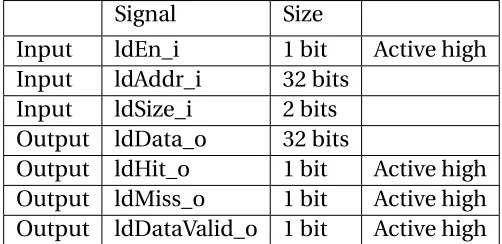
• The cache load input from the upper_hierarchy are as shown in Table 2.4. The cache
supports loads with different sizes. The naming scheme remains similar to the one
used in store signals.
Table 2.4Core-to-cache. Load interface signals
Signal Size
Input ldEn_i 1 bit Active high Input ldAddr_i 32 bits
Input ldSize_i 2 bits Output ldData_o 32 bits
Output ldHit_o 1 bit Active high Output ldMiss_o 1 bit Active high Output ldDataValid_o 1 bit Active high
• The different valid sizes are shown in table 2.5.
Table 2.5Load sizes
Value Size
00 Byte 01 Half-Word 10 Word
2.3. LOAD FEATURES CHAPTER 2. CACHE SPECIFICATION
naming scheme "dc2mem" and "mem2dc" signify the initiator and target module in
that order. For example dc2mem specifies that the initiator is data cache and target is
memory.
Table 2.6mem2cache interface signals
Signal Size
Output dc2memLdValid_o 1 bit Output dc2memLdAddr_o 28 bits Input mem2dcLdCpkt_i 2 bits Input mem2dcLdTag_i 21 bits Input mem2dcLdData_i 128 bits Input mem2dcLdValid_i 1 bit
2.3.2
Load request and responses:
• The upper hierarchy sends a load requests using the ldEn_i, ldAddr_i, ldSize_i signals.
• The responses to load request coming from the upper hierarchy should be given in
the same cycle, i.e., hit/miss should be valid at the next clock edge. Each load request
should result in either one of the hit or miss signals to be valid.
• If the result is a load hit, the data and the data valid signals should also be valid at the
next clock edge. The ldData_o, ldHit_o, ldMiss_o and ldDatavalid_o signals are used
to send the response.
2.3.3
Load sizes:
• Cache supports load requests of different sizes.
• The load data output sent using the ldData_o for each size will be aligned to the LSB
2.3. LOAD FEATURES CHAPTER 2. CACHE SPECIFICATION
significant half-word and rest of the bits will be zero; a byte will be aligned to the LSB
and rest bits will be zero.
2.3.4
Non-blocking interfaces:
• The cache interfaces are non-blocking. It can accept requests even after suffering
a cache miss from the upper hierarchy and doesn’t block any interactions with the
lower hierarchy.
• The cache has one Miss Status Handling Register. It can handle and re-fill a single load miss at a time. But as mentioned earlier, it can still handle new requests from the
upper-hierarchy when pending on a cache-miss and can send hit/miss responses.
But it cannot handle more than one cache-refills at a time.
2.3.5
Store-load forwarding:
• The cache implements store-load forwarding. If a data requested by the load is present
in the cache line and in the store buffer, the data in the store buffer is forwarded since
it is more recent than the one in the cache line.
• The same address can be stored at many positions in the store-buffer owing to
mul-tiple store requests to the same address. We always chose the most recent entry to
forward.
• Different sizes of the load and store makes store load forwarding complicated. We
only forward data in the store buffer if the load size requested is less than or equal
to the store size in the store buffer. We also ensure that the addresses are perfectly
aligned. This is done to simplify the implementation of store-load forwarding. Such
cases, where the requested data is only partially present or isn’t properly aligned, are
referred to as "partial hits". In the case of partial hits, not only do we not forward the
data from the store buffer, we cannot send the data stored in the cache line since it
would be stale. If the most recent hit in the store-buffer is a partial hit, we have to
2.3. LOAD FEATURES CHAPTER 2. CACHE SPECIFICATION
2.3.6
Cache fill request and response from lower hierarchy:
• The cache can forward a load request to the lower hierarchy if it misses in the cache
and the MSHR is empty. The dc2memLdAddr_o and dc2memLdValid_o signals are
used to send this request.
• The lower hierarchy responds with a 128 bit data line. The mem2dcLdCpkt_i,
mem2dcLdTag_-i, mem2dcLdIndex_mem2dcLdTag_-i, mem2dcLdData_i and mem2dcLdvalid_i signals are used for this.
• The mem2dcLdCpkt_i signal stands for load command packet signal. The commands
from lower hierarchy can be used to fill a cache line or to invalidate a cache line.
Command packet signal is used to differentiate between the two. The command for a
cache line fill is 0x1, that for invalidate is 0x2.
• The cache fill request should be sent only when the address isn’t present in the cache
line. A miss resulting due to a partial hit when the data is already present in the cache
shouldn’t be forwarded to the lower-hierarchy.
2.3.7
Miss Status Handling Register (MSHR):
• The cache has one MSHR.• The MSHR is used to store the state of a cache fill request sent to the lower hierarchy.
The cache can send such a request only if it has enough space in the MSHR to store
the state of the request. Consequently since we have only one MSHR, we can only
have one outstanding fill request at a time.
• Any further cache misses that occur after one fill request has been sent are not
sched-uled for fill till the first request is satisfied.
• Data that is received from the lower hierarchy is matched against the MSHR to ensure that we are receiving the correct address. Only if the address for the response matches
2.3. LOAD FEATURES CHAPTER 2. CACHE SPECIFICATION
• It is required by the upper hierarchy to keep on retrying for a hit, the cache doesn’t
give a notification to upper-hierarchy if the outstanding fill request was completed.
• The MSHR also has the feature of storing the store requests that went through the
cache for the address that the MSHR stores. We’ll discuss this feature in a different
section.
2.3.8
MSHR delays:
• If the cache suffers a miss in the cache line and the MSHR has space for the new
request, the following is the sequence of events:
– Clock cycle N: Load request, misses in the cache line and the MSHR isn’t valid.
– Clock cycle N+1: Cache-fill request is sent to the lower hierarchy. The MSHR is
filled with the address.
• If the lower hierarchy responds with the data, the sequence of events is as follows:
– Clock cycle N: Cache-fill Data received from the lower hierarchy corresponding
to the MSHR state.
– Clock cycle N+1: Cache-line is filled, MSHR is cleared.
– The data filled in the cache line can only be valid in cycle N+2.
– Although the MSHR also is cleared and valid to receive a new request in cycle
N+2, the cache has flags to let it know that the MSHR is going to be cleared the
next cycle. So, if a load request from upper hierarchy is received in cycle N+1, in
cycle N+2, the MSHR will be filled with the new address and a load request is sent to the lower-hierarchy.
2.3.9
MSHR data:
• Once a load request has missed and a cache-fill request for the address is sent to
the lower hierarchy, the address is stored in the MSHR. It is possible for the upper hierarchy to send store requests to addresses in the same cache line. These store
2.4. INVALIDATION REQUESTS: CHAPTER 2. CACHE SPECIFICATION
• We have seen that when a store request commits, we merge the data with the
cache-line if the address exists in a cache-cache-line.
• For the address corresponding to the MSHR state, the address is going to be filled in a
cache-line soon. If we have stores committing to the same cache line, we store the
data in a "MSHR data" structure.
• This data is then merged with the incoming data when it is received from the lower
hierarchy.
2.4
Invalidation requests:
• The lower hierarchy of the memory sends invalidation requests to the cache using the
same interface that is used to send cache-fills. The signals used are mem2dcLdCpkt_i,
mem2dcLdIndex_i, mem2dcLdValid_i.
• The other signals of the load interface mem2dcLdData_i and mem2dcLdTag_i aren’t
used for invalidation.
• This is because the tag field isn’t used to check for invalidation. The lower memory
hierarchy keeps a directory to indicate which addresses are stored in the cache. The
directory will take care not to send an invalidation request if the target address isn’t
present in the cache.
• The value of load command packet for invalidation is 0x2.
2.5
Scratch mode:
In the Scratch mode, the cache acts like a SRAM. There is no load miss or store miss. Every
command results in a hit. That is why it is important to ensure that every address that we
2.5. SCRATCH MODE: CHAPTER 2. CACHE SPECIFICATION
2.5.1
Scratch-mode interface signals:
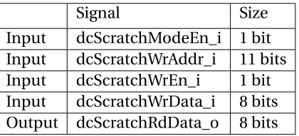
The scratch-mode signals are shown in table 2.7.Table 2.7Scratch Mode Interface signals
Signal Size
Input dcScratchModeEn_i 1 bit Input dcScratchWrAddr_i 11 bits Input dcScratchWrEn_i 1 bit Input dcScratchWrData_i 8 bits Output dcScratchRdData_o 8 bits
• As can be noted, the load and store interfaces had a 32 bit data bus and a choice of
selecting different sizes. The scratch interface on the other hand has a resolution of 1
byte.
• We don’t check tags in the scratch mode, so the write address is only 11 bits long, i.e.,
index bits and the byte offset.
• The data on dcScratchWrData_i is written to the cache address dcScratchWrAddr_i
when dcScratchWrEn_i and dcScratchModeEn_i is high on the next clock edge.
• The dcScratchRdData_o signal has the data stored at the dcScratchWrAddr_i as
out-put.
2.5.2
Load interface for scratch-mode:
• The load interface stays mostly the same for scratch-mode. We use the same signals
for a load access and to signal the load output. But, the internal functionality changes.
• We are said to be in scratch-mode if dcScratchModeEn_i was high in the previous
2.5. SCRATCH MODE: CHAPTER 2. CACHE SPECIFICATION
• In scratch-mode, if upper hierarchy sends a load request, the cache forwards the data
present in the cache line irrespective of the value of cache valid bit and the tag value.
In short, every load access results in a hit.
• Since, there isn’t a miss, no cache-fill request is sent to the lower hierarchy.
2.5.3
Store interface for scratch-mode:
• Store interface stays almost the same. But the internal functionality changes.
• Instead of storing the command in the store buffer and waiting for the lower memory response, the cache commits the store immediately to the cache line.
• The cache doesn’t send the store to the lower hierarchy, it doesn’t check if the address
is actually present in the cache. The result is always a store hit.
In the next chapter we discuss the structure of the testbench developed using
CHAPTER
3
OOP-TESTBENCH
The SystemVerilog language has many features in itself to make a verification environment
modular and reusable. It has classes, interfaces, tasks, synchronization elements, coverage
collecting constructs, etc. The use of classes makes the SystemVerilog an Object-Oriented
hardware verification language. In this chapter we’ll describe a testbench that follows
sim-ple rules of the SystemVerilog language. We’ll call this a OOP-testbench[3]because it uses
the object-oriented programming constructs of SystemVerilog that help in making the
test-bench modular. This will act as a baseline for comparison to the UVM-based testtest-bench. We
will quantitatively measure the effort needed to add tests or features to the OOP-testbench and compare it to the effort required for the same tasks in the UVM-based testbench.
The basic principle behind development of the testbench for a complex design is to
separate the many tasks into components. This enables the same testbench to be used for
different kinds of tests including directed as well as constrained-random tests. It allows
small-changes to be made to each module as long as the interfaces between different
3.1. INTERFACE: CHAPTER 3. OOP-TESTBENCH
• Generating stimulus
• Applying stimulus to the DUT
• Monitoring the responses from the DUT
• Generating ideal responses for the generated stimulus
• Comparing the ideal response to the DUT response
• Gathering coverage information on the generated stimulus
Each of the above functionality should be executed by different components. These
com-ponents should be separated from each other to make the structure reusable. Each of the
testbench component is then divided into classes. Each class could possibly have its own
thread to manage its functionality internally. This makes managing the data and the
pro-cesses very simple. In the following sections of the chapter we’ll look at each of testbench
tasks and discuss which class takes care of each of these tasks.
Once these classes are defined along with the data and threads they encapsulate, they
need to be connected to each other. SystemVerilog provides mailboxes for connections
between different threads. As discussed earlier the interfaces need to be well-defined to
make the testbench re-usable. The interfaces between these connections would be the
class objects that will be passed using the mailboxes. Figure 3.1 shows the general structure
of a OOP-testbench.
Before going into the details of the existing OOP-testbench structure, we’ll first delve into
the SystemVerilog interface that we’ve used for the testbench and the transactor construct
which will be used extensively in the testbench.
3.1
Interface:
We’ve used the SystemVerilog interface construct to connect components of the DUT to the
testbench. Since the testbench needs to apply stimulus and verify the responses, we need
some way of providing the signal-level information of the DUT to the components of the
3.2. TRANSACTOR: CHAPTER 3. OOP-TESTBENCH
Figure 3.1OOP-Testbench Structure
is a place where we have bundled all the inputs/outputs of the DUT in one place. Instead of passing all the signals between the components, we need to only pass the interface. This
makes adding, removing, modifying signals easier.
3.2
Transactor:
There are multiple definitions of a transactor. For our purpose a transactor is a class which
has a specific structure. It is a construct which can have multiple threads. Each thread can
have a single source (usually a mailbox or similar for SystemVerilog) from which it gets
data in the forms of packets. The thread processes the packet of data, maybe generates its own packet based on the input packet and has a single destination (destination mailbox)
to which it sends the output packet.
The transactor has a main thread which spawns all the other threads in the class. It can
have other threads which don’t have mailboxes, but support the transactor’s functionality.
But a single thread usually takes care of spawning all the other threads. A transactor structure
is shown in Figure 3.2.
The main thread is usually called the run() task. A component using a transactor need
only be aware of this run() task and spawn it. The transactor’s run() task will take of spawning
3.2. TRANSACTOR: CHAPTER 3. OOP-TESTBENCH
3.3. GENERATING STIMULUS. TESTER: CHAPTER 3. OOP-TESTBENCH
3.3
Generating stimulus. tester:
The testbench should generate stimulus corresponding to the test that needs to be run
on the DUT. Since, we need to run a wide range of tests, the stimulus will change. So we
should keep generating and applying stimulus separate from the rest of the structure of
the testbench. Moreover, "generating" stimulus should be kept in a different class from
"applying" stimulus to the DUT. There are multiple reasons for doing this.
First, applying stimulus will be done by changing input signals of the DUT. As the signals
can change in the future, the changes due to changing signal definitions should be localized
to a single class.
Second, we would like our stimulus and the testbench in general to be at the transaction-level. Rather than dealing with all the signal-level details, we would like to deal with the
input stimulus and generated responses as transactions. As we will see, transaction-level
modelling of the DUT is much easier than making a cycle-accurate model of the DUT.
Third, the generated signal itself can be complex and may need many layers to it. For
example, for a networking application, we may have to generate layered packets as stimulus
and check if errors in each layer are handled properly by the DUT. Hence the stimulus
generation itself can be divided into multiple classes. Thegeneratorclass is what deals with the generation of stimulus and passing the transaction to thedriverclass which takes care of applying the stimulus to the DUT. As can be seen from Figure 3.1 we have the test class also as part of the stimulus. The test is shown as an external component to the testbench
because it changes for every test we want to run.
The generator can be designed as a transactor. In its run task it receives information
from the test, create its own transaction packets and sends them to the driver. It can be
thought of that thegeneratorcreates the input packets and thetestclass provides it with specific directions to generate these packets. The test can thus direct the generator to create
packets that form a sequence of input transactions to achieve the test objective. In our
design, thetester class acts as the generator. It has a single thread where it creates the transactions and sends them to the driver through a mailbox. It creates the transactions through a function called get_transaction(). The run() task takes an integer argument to
3.4. APPLYING STIMULUS. DRIVER: CHAPTER 3. OOP-TESTBENCH
Figure 3.3Tester run() task
The get_transaction() function is overridden by the specific test that is currently executing.
The function directs the type of transactions to be generated. This function acts as the
communication between thetestclass andtester.
3.4
Applying stimulus. Driver:
The driver receives the transaction objects from the generator and converts them to pin
wiggles on the DUT interface. The driver needs a copy of the DUT interface to get access to
the DUT signals. The interface is passed to it as an argument when the driver is instantiated.
It is important to note that in general the inputs are always applied just after the clock-edge
so that they are valid at the next clock-edge.
The driver is also a transactor, waiting on the generator mailbox for packets. On receiving
a packet, they are deciphered in terms of values to be applied to each signal. The driver then applies these values to the DUT interface signals.
In our testbench, we’ve decided to model all the interfaces between the cache and
the outside world in the testbench itself. The cache has two interfaces: one to the
3.4. APPLYING STIMULUS. DRIVER: CHAPTER 3. OOP-TESTBENCH
Figure 3.4Driver run() task in the driver.
Currently we generate only upper-hierarchy input packets in the tester. The lower-hierarchy inputs are generated in the driver itself using the default $urandom functions.
We have four different threads to handle all the functionality:
1. Core thread: Waits on the generator mailbox. If the received packet is a core input,
apply it to the core input signals.
2. Memory thread: Get memory inputs from the core thread and store them in a queue
to be used later. Monitor the DUT interface to detect either a load or store request
going to the memory. Once a request is detected, notify the Load or Store thread
about it.
3. Load thread: If a load request is received, wait for a random amount of time and send
randomized data to the load input of the DUT.
4. Store thread: If a store request is received, wait for a random amount of time and send
store complete transaction to the DUT.
The run task of the driver is shown in Figure 3.4. It forks off 4 threads that we described
3.5. TESTER TO DRIVER INTERFACE: CHAPTER 3. OOP-TESTBENCH
3.5
Tester to driver interface:
The interface between the tester and the driver is a class which is used to send the input data
through the mailboxes connecting them. In our design the class is calledcore_cache_if. It is in the cache_core.sv file of the code distribution. Figure 3.5 is a snippet of the class. Many
of its internal variables are defined as random so that we can use the default randomize
function of SystemVerilog to generate randomized transactions. The constraints are defined
so that the inputs stay valid according to the cache specifications. These constraints are
necessary since we would not want our randomized stimulus to be an invalid input to the
design-under-test, unless we are testing for error conditions in the inputs.
3.6
Monitoring the responses from the DUT. Monitor:
The DUT will respond to the stimulus that we apply to its inputs. As we are modeling both
the upper-hierarchy and lower-hierarchy interfaces, we need to test both these interfaces.
The upper-hierarchy interface is fundamentally different from the lower-hierarchy interface
because many outputs (load hit, load miss, load data valid, etc.) are asynchronous. We
have made a design choice of monitoring the output of the two interfaces separately. This
reduces the complication in monitoring and checking the two interfaces. These output transactions are sent to the checker class.
We have also made a design choice of monitoring the input signals on the interface
and sending them to the scoreboard, rather than sending the generator packet to both
driver and scoreboard. While the generator packet itself can be sent to the scoreboard,
it adds complications to the scoreboard. The generator transaction may contain details
like delays which the driver class decodes and sends the signals to the hardware-interface.
The scoreboard shouldn’t have to handle the same things again, since it is a
transaction-level class. Moreover, the generator only generates the upper-hierarchy/core input and
the memory input is generated by the driver. So it is important for us to create the input transactions in the monitor and send them to the scoreboard. The input transaction isn’t
divided into two interfaces like the output transactions are, we still handle them together.
3.6. MONITORING THE RESPONSES FROM THE DUT. MONITOR:CHAPTER 3. OOP-TESTBENCH
3.7. GENERATING IDEAL RESPONSES. SCOREBOARD: CHAPTER 3. OOP-TESTBENCH
Figure 3.6Monitor run() task
monitor will not only detect the responses from the DUT, it will also convert them into
transactions. Hence, any meaningful exchange on the interface is to be converted into transactions. And only when we have a transaction, we send the monitored packet to other
classes. The monitor will also need a copy of the interface since it is the pin-level signals
that it is monitoring. The monitor isn’t exactly a transactor, because it responds to changes
in signal-level information rather than on input transactions. But its structure is similar. It
has a run task which spawns threads to monitor the two interfaces and to send the detected
input and output transactions to the scoreboard. A snippet of the monitor run task is shown
in Figure 3.6.
3.7
Generating ideal responses. Scoreboard:
Scoreboard is the class that generates ideal responses for the inputs applied to the DUT.
Since the scoreboard is a transaction-level class, it doesn’t need to generate cycle-accurate
responses. This makes the scoreboard very much like a procedural code rather than a
RTL-like behavioral code. Thus the scoreboard is much easier to develop, debug and change as
compared to the DUT.
Scoreboard is a transactor. In the run task, it receives input transactions from the monitor.
It processes the input and generates two set of transactions: the upper-hierarchy/core
3.8. COMPARING THE RESPONSE. CHECKER: CHAPTER 3. OOP-TESTBENCH
While the scoreboard need not be cycle-accurate, it should be cycle aware in some
sense. For example, if an input stimulus generates two different outputs separated by a
few cycles. We need to make sure that these two outputs are generated as two different
transactions and any output transactions between these two are sent in order. To ensure
this, the monitor sends a input transaction every rising-edge of the clock, even if we don’t
have any valid input to the scoreboard. It can be thought of that the clock-edge itself is an input to the scoreboard.
3.8
Comparing the response. Checker:
The checker class compares the output transactions from the monitor to the ideal output
transactions generated by the scoreboard. Since both interfaces have different mailboxes,
the checker has four mailboxes in total.
The class has six different threads. Four threads (one for each mailbox) to wait on
mailboxes, one thread to compare upper-hierarchy outputs and one thread to compare the lower-hierarchy outputs. We could have manage all the functionality in fewer threads, but
having different threads for each functionality makes things much simpler.
The four threads that wait on a mailbox pick the transaction from the mailbox and push
it into a dedicated queue for each of the four transactions. They notify the checker thread
that a new transaction has arrived. The checker threads check if we have at least one thread
each from monitor and scoreboard. If we do, it pops the first transactions from both queues
and compares them. It flags an error when it sees a mismatch. We can decide how to handle
the error, we could stop the simulation and dump the two mismatching transactions or we
could just dump the error transactions and continue with verification.
3.9
Gathering coverage information. Coverage:
The coverage class is what takes care of collecting coverage. The monitor sends the
in-put transactions to the coverage class too. In the class we have defined covergroups and
coverpoints. The coverage is a transactor, in the sense that has a single thread waiting on
3.10. TESTBENCH CLASS: CHAPTER 3. OOP-TESTBENCH
Figure 3.7Testbench run() task
In this thread, the class samples all its covergroups to gather coverage on the input
transaction. The coverage is also a transaction-level class, it isn’t aware of the cycle level
behavior of the inputs. Therefore, for measuring coverage on the delays, specific delays
need to be measured in the monitor class and sent to the coverage.
3.10
Testbench class:
The testbench class is where all the components of the testbench fit together. We’ve
dis-cussed that every class has its own run() task which is a forever running thread. This consistent structure helps in developing the testbench class.
In its constructor, the testbench class instantiates all the classes that we discussed:
driver, monitor, scoreboard, checker and coverage. It sends the necessary arguments to
each class’s constructor. It has a run() task of its own where it spawns threads for all the
component classes. The run task for the testbench is shown in Figure 3.7.
The tester shown in the snippet (Figure 3.7) can be related to any test that we want
to run. The specific test will extend the tester module. And it will be instantiated in the
testbench class. Hence to run a different test, we replace the tester in the testbench by a
3.11. PUTTING IT ALL TOGETHER. TOP MODULE: CHAPTER 3. OOP-TESTBENCH
3.11
Putting it all together. top module:
Once we’ve created out testbench, we need a hierarchy to instantiate it and to connect it to
the DUT. This is done in a top-level module, which in our case is called the top module.
Unlike our testbench components, it is a Verilog module rather than a class. The top module
does the following things:
1. Generates the clock for the DUT
2. Instantiates the SystemVerilog interface. It connects the generated clock to the
inter-face
3. Instantiates the DUT. Connects the DUT inputs and outputs to the corresponding
interface signals.
4. In an initial block instantiates the testbench class. We send the interface as an
argu-ment to the testbench constructor for components that need it.
5. In the same initial block starts the testbench by calling the run() task of the testbench.
The argument n to the task is how many packets do we want to generate for the test.
This argument is passed to the tester’s run() task.
3.12
Comments:
Now that we have the structure of the OOP-testbench, we can make a few observations:
• The testbench is in itself quite modular. Components handle very specific tasks. Tasks
that are related but can be changed are separated into different modules. For example,
new tests can be added by changing the tester class, without changing any other class.
• Layered structure and a transactor skeleton works well as we can instantiate a single
class and just call the run task in the top hierarchy for all the classes to start executing.
• The DUT interface is passed to two different classes: driver and monitor. No other class uses it. The interface has to be passed through the testbench class, not because
3.12. COMMENTS: CHAPTER 3. OOP-TESTBENCH
• Changes to the DUT signals will need changes in interface, driver and monitor.
• The monitor needs to send the input transaction to both scoreboard and coverage
classes. It needs to have different mailboxes for both. In future if we divide the coverage
class into further classes or any other class is introduced which needs the input
transaction, we will need to change the monitor to add another mailbox to it.
• To run different tests on the testbench, we need to inherit the tester class and override
the get_transaction() function of the class to generate new stimulus. This new class
will then be instantiated in the testbench. So, we need to change our testbench class
and instantiate a new testbench class in the top module for every new test. Even
for tests for which the corresponding tester classes were already created, we need
to change the testbench code, re-compile it and then use it. This makes switching
CHAPTER
4
UVM-BASED VERIFICATION SUITE
We’ll focus on the structure and the development of the UVM-testbench in this chapter. We
describe how the baseline OOP-testbench was modified to use the UVM-features. UVM is a
feature rich methodology which can be used for designs much more complicated than the
one we are concentrating on. Unlike the OOP-testbench where we can have one test in a
compile, UVM allows us to have a suite of tests ready to run without any need to recompile.
This is why we call it a verification suite instead of a testbench.
We won’t be going into the details of all the features that UVM offers. We want to focus
on the features we used in making our testbench better. First, in section 4.1 we will delve into the UVM features that we have used. In section 4.2 we will discuss the changes that we
4.1. UVM FEATURES CHAPTER 4. UVM-BASED VERIFICATION SUITE
4.1
UVM features
In this section, we’ll be describing UVM features and base classes that we’ve used. While the
description of each class doesn’t go into the details of all the component methods and data,
we’ll concentrate on the parts that are critical to understanding the changes we made. The
UVM Cookbook[2]is an excellent resource to understand all the implementation details of
the base-classes.
4.1.1
uvm_component and uvm_object
A UVM verification environment has two types of objects: the objects that form the structure
and functionality of the testbench and objects that carry data for the testbench. UVM divides
all its classes into these two broad types.
• Every class which is designed to act as a structural and functional aspect of the testbench is inherited from a uvm_component base class, e.g., driver, monitor,
score-board.
• Every class that is designed to carry data is inherited from a uvm_object base class,
e.g., transactions, coverage data, monitor input packets, etc.
The routines and data inside these base classes differ according to the purpose of each
base-class. All the other classes in UVM are inherited from either of these two classes.
4.1.2
UVM factory
The UVM Factory Pattern is a design pattern[3]that creates objects for us. Every class in
the UVM hierarchy is registered with the UVM Factory. The Factory can create objects that are registered with it. It is like a large case block which selects which object to create
depending on the arguments that are passed to it. The Factory also correctly typecasts the
object created according to its LHS class type. It is up to the user of the Factory to ensure
that such typecasting will be valid.
The purpose of using the Factory is to change the type of object to be created not by
4.1. UVM FEATURES CHAPTER 4. UVM-BASED VERIFICATION SUITE
Figure 4.1UVM Factory
Figure 4.2UVM Factory in action
situations, we want to change objects in the testbench based on many factors, e.g., the test
that is being run currently. In the testbench class in the OOP-testbench Section 3.10, we
instantiate and run different tester objects depending on the type of test we want to run.
Instead of hard-coding the type of tester object we create in the testbench[3], if we create
the object using the UVM Factory, we can change the type of test by providing different
argumentsduring the simulation (Figure 4.2). We don’t need to change the testbench class or recompile the whole testbench. In a complicated testbench, there will be multiple
instances where we would want to change the type of object to instantiate depending on
many factors. The UVM Factory will be useful in every such instance.
We use macros provided by UVM to register classes with the Factory. uvm_component
and uvm_object are registered using different macros. Classes extending uvm_component
4.1. UVM FEATURES CHAPTER 4. UVM-BASED VERIFICATION SUITE
Figure 4.3Registering Object with Factory
Figure 4.4create() function to instantiate objects
Class instances are instantiated using a differentcreate() function defined by UVM instead of a constructor call so that the instantiation goes through the Factory. Figure 4.4 is
an example of the use of create() function for the class we registered.
The create() function for uvm_objects takes one argument
• typestring: name of the object to uniquely identify it.
For uvm_component create() takes two arguments
• typestring: name of the component to uniquely identify it.
• typeuvm_component: parent component of this component. When a class
instanti-ates an object it passes its own pointer, i.e., thethispointer as the parent. This helps
UVM form a graph of the hierarchy of the testbench.
4.1.3
UVM configuration database:
Some objects or variables values (like the SystemVerilog interface) are needed by multiple
components. Instead of passing these objects or values throughout the testbench, UVM
uses a configuration database to store these. Components that need the value retrieve
them from the database. Figure 4.5 is an example of the an BFM object being stored in
the uvm_config_db in the top module. We’ll see more about the BFM in section 4.2.1. The
object can be retrieved later using the get() function of uvm_config_db by the driver (Figure 4.6).
The database is parametrized by the type of object being stored. In our case it is a "virtual
4.1. UVM FEATURES CHAPTER 4. UVM-BASED VERIFICATION SUITE
Figure 4.5Storing in uvm_config_db
Figure 4.6Retrieving from uvm_config_db
retrieve it. The first two arguments are the storage location for the object handle. We want
the object to be available throughout the entire testbench, so our arguments are "null" and "*". The third argument is the name of the data to be stored and the fourth is the data
itself. The name and the parameter arguments are needed when retrieving the data from
the uvm_config_db.
4.1.4
UVM phases
The UVM factory helps in constructing the testbench by instantiating all the testbench
objects for us. The user needs to specify the hierarchy by instantiating objects inside the
components using the create() instead of new() functions. UVM needs the testbench
cre-ation and simulcre-ation to run in a particular order. This is enforced by certain functions and
tasks in the uvm_component class that the child classes should override.
The UVM testbench simulation cycle is divided into what are called phases. We’ll take a
brief look at some of the UVM phases relevant to our testbench.
• build phase: All the objects in the structure are instantiated in this phase. The
simu-lation starts with the UVM root node component being constructed. After this, the
build_phase() methods of all the components are called in top-down order of
hierar-chy. So, first the top-most class is instantiated, then its build_phase function is called.
If a component needs to instantiate objects, it should do so in the build_phase()
method. The build_phase functions for all these instantiated objects is then called.
4.1. UVM FEATURES CHAPTER 4. UVM-BASED VERIFICATION SUITE
talking about instantiating testbench components. Hence, uvm_objects relevant to a
uvm_component’s functionality need not be instantiated in the build_phase.
• connect phase: The various connections between components are made in this phase.
This phase is called after the build phase execution is complete, so UVM assumes that
all components have been instantiated. In this phase, connect_phase() function of
all components are called in the bottom up hierarchy order. Each component makes the connections for its internal objects in its connect_phase() method.
• end of elaboration phase: This phase is executed after the connect phase.
Adjust-ments to the testbench to be made after the connect phase, if any, are made in this
phase. This is done by calling end_of_elaboration_phase() function for all
uvm_com-ponents in bottom up order.
• run phase: This part of the simulation is the key to the execution of each test. The
UVM simulation engine starts this phase for all components simultaneously by calling
their run_phase() tasks. Like in SystemVerilog "fork-join" construct, the execution sequence for the run_phase tasks of all the components is non-deterministic. So the
synchronization between the run phases of all components should be taken care
of by the testbench designer. The stimulus generation and application, checking of
signals and coverage gathering happens in this phase.
• report phase: When the run phase execution concludes, report_phase() functions
for all the components is called. This is used for the purpose of reporting vital stats
related to the executed tests.
UVM has many other simulation phases which we aren’t focusing on now. These other phases too are handled by specific methods in each component class. The uvm_component
definition comes with these phase methods. The components wanting to use any phase
must override the corresponding phase method.
Of the phases we discussed, except the run_phase all other phases are functions. The
run_phase is a task since it needs simulation time to generate stimulus and check results.
4.1. UVM FEATURES CHAPTER 4. UVM-BASED VERIFICATION SUITE
Figure 4.7constructor and build_phase
Not all components may need all the phases. For example, certain components may not
have any components within them and may not need to override the build_phase method.
Certain components may not participate directly in the stimulus generation or monitoring
responses part of the testbench, they might be in place to define structure rather than
function. Such components won’t need to override the run_phase task.
4.1.5
Raising objections
Since, the UVM itself instantiates and runs the phases for all the component classes, it
cannot decide on itself when to terminate the run_phase. So, it follows a simple rule: it terminates a phase if not explicitly told to wait. Usually for a testbench, the run_phase is
where most of the simulation occurs. It is also the phase which can consume simulation
time. In the OOP-testbench, the forever loops for all the run() tasks ensured that we won’t
stop the simulation. We explicitly stopped the simulation when we were done generating
stimulus. We do the opposite in the UVM testbench: we explicitly tell the UVM simulation
engine to wait till we are done.
This is done throughobjections. Each phase related function/task has an argument
called phase which is of type uvm_phase. This argument is used by the UVM simulation
4.1. UVM FEATURES CHAPTER 4. UVM-BASED VERIFICATION SUITE
Figure 4.8Raising Objections
method, letting UVM know that it needs to stay in this phase. This acts like a flag which UVM
checks before moving on to the next phase. If a single objection is raised, UVM waits in that
phase. Once the component is done, it can drop the objection using the drop_objection method in the phase. When all objections are dropped, UVM moves on to the next phase.
Figure 4.8 is a code snippet showing a test raising an objection before generating
stimu-lus and dropping an objection after it is done. raise_objection and drop_objection have
one argument which is the pointer to the component raising the objection.
4.1.6
Observer design pattern
[
3
]
In Chapter 3 comments section 3.12, we observed that in some cases of the OOP-testbench,
we needed multiple mailboxes to send the same data to different modules (Figure 4.9).
While this works, this limits the reusability of the modules. If in future we need to add more
modules that need the same data, we’ll need to add more mailboxes sending the same data.
We’ll also have to add connections between the new module and the generating module.
The connections of a monitor to scoreboard, monitor to checker and monitor to coverage are very typical of every testbench. And the multiple mailboxes problem will arise in every
case. UVM has the observer design pattern to simplify cases like this. It is useful in every
case where there is a single generator and many consumers (or what UVM calls observers).
4.1. UVM FEATURES CHAPTER 4. UVM-BASED VERIFICATION SUITE
Figure 4.9Connections using multiple mailboxes
UVM implements observer design pattern using the uvm_analysis_port and analysis_export
constructs (Figure 4.10). These constructs, like mailboxes, take parameters of the type of
data we want to send. Specifically, they can only communicate with each other through
classes of type uvm_transaction.
4.1.6.1 uvm_transaction:
The uvm_transaction is inherited from the uvm_object and acts as a base class to all
trans-action level objects used in the testbench. For example, data passed between the monitor
and the scoreboard should be of type uvm_transaction. It inherits all the properties of
uvm_objects and provides timestamp properties, transaction recording properties[2].
4.1.6.2 uvm_analysis_port:
The uvm_analysis_port is inherited from uvm_component. It can connect and
commu-nicate to another UVM construct called analysis_export through objects of type uvm_-transaction. A single uvm_analysis_port can connect to multiple analysis_exports. It is a
parametrized class, the parameter being type of uvm_transaction that can be sent using
the port. uvm_analysis_port has a write() function. Argument to write() function is the data
to be sent to the observers. The parent class instantiating the uvm_analysis_port calls the
4.1. UVM FEATURES CHAPTER 4. UVM-BASED VERIFICATION SUITE
Figure 4.10Observer Design Pattern connections
the uvm_analysis_port calls the write() functions of all analysis_exports connected to it
and sends them the data passed to these write() functions.
For our generator-observer design pattern, the generator instantiates a
uvm_analysis_-port in it. All the classes that wish to be an observer for the generator, connect to this
uvm_analysis_port. We’ll see in further sections how to connect to uvm_analysis_ports.
4.1.6.3 uvm_subscriber:
uvm_subscriber is extended from the uvm_component. Along with the uvm_component
routines, it provides an analysis_export to connect to a uvm_analysis_port and it also provides a write() function. It is a parametrized class, the parameter being of the type
uvm_transaction the analysis_export can receive.
Observers extend the uvm_subscriber and override the write() function to handle the
incoming data from the generator. The observer’s analysis_export is connected to the
uvm_analysis_port of the generator. An analysis_export can be connected to only one