Influence of Process Variables on Cutting Induced
Workpiece Temperature in High Speed Milling of
Al-Si-Mg-Fe Alloys Using Taguchi’s Technique
S.Madhava Reddy 1, A.Chennakesava Reddy 2
1
Associate Professor, Dept. of Mechanical Engineering, MGIT, Hyderabad-500 075, India
2 Professor, Dept. of Mechanical Engineering, JNTUH, kukatpally, Hyderabad- 500 085, India.
ABSTRACT:In this paper, the experimental investigation was carried out with straight flute end milling cutters for high speed end milling of the Al-Si-Mg-Fe alloy materials. Machining induced workpiece temperatures can be controlled by changing the machining conditions. For determining the distribution of workpiece temperatures for end milling of aerospace aluminum alloys used. The cutting temperature depends upon the cutting speeds, depth of cuts and feed rates. The cutting temperature increases with an increase in the depth of cut and feed rate and decreases with an increase in the cutting speed. Machining of Al-Si-Mg-Fe alloy should be carried out at high speeds and feeds to minimize temperature rise in the work piece. The long term effects of continuous heat input from the cutting tool should affect workpiece material properties due to the accumulated rise in temperature of the work piece. This behavior can be attributed to the precipitation hardening and thermal stability in the alloy.
KEY WORDS: High speed machining; Heat generation; Precipitation hardening; Aluminum alloys
I. INTRODUCTION
Machining of metals is not completely understood because of the highly non linear nature of the process and the complex coupling between deformation and temperature fields. Metal cutting can be associated with high temperature in the tool-chip interface zone and hence, the thermal aspects of the cutting process strongly affect the accuracy of the machining process. The deformation process is highly concerned in a very small zone and the temperatures generated in the deformation zones affect both the tool and the work piece. High cutting temperatures strongly influence too wear, tool life, work piece surface integrity, chip formation mechanism and contribute to the thermal deformation of the cutting tool. The ever increasing demand on cost reduction and improving quality of final products are driving metal cutting research into new areas. As for high speed machining (HSM), it has become a key technology of particular relevance to the aerospace, mould and die and automotive industries. In HSM. Cutting speed has a predominant effect on the cutting temperature and the heat transfer mechanism. As cutting speed increases, the cutting process becomes more adiabatic and the heat generated in the shear deformation zone cannot be conducted away during the very short contact time in which the metal passes through this zone. Consequently, highly localized temperature in the chip occurs. Therefore it appears that in HSM, where the process is nearly adiabatic the effect of the thermal phenomenon should become more important[1].
emerging technology, which reduces the machining time significantly. The milling process is a highly non-linear plastic deformation process. In the milling operations, the cutter rotates at a high speed and because of the multiple cutting edges it removes metal at a very fast rate. The reliability of machining increases by making the workpiece less prone to distortion. During metal removal process, a large amount of heat is generated. Most of the heat is taken away by the chip, some amount of heat flows into the tool, some is dissipated to the surrounding and the remaining heat flows into the workpiece.
II. EXPERIMENTAL APPROACH
Al-Si-Mg-Fe alloy is highly thermal conductive in nature. The heat, which flows into the workpiece, results in thermal distortion. In order to machine the Al-Si-Mg-Fe alloy workpiece to a closer tolerance, it is essential that the heat flow into the Al-Si-Mg-Fe alloy workpiece must be minimized.
In the present work, the influence of end milling on heat generation in Al-Si-Mg-Fe alloys, which was cast by sand, investment, and die casting methods, was investigated. The end mills have cutting teeth on the end as well as on the periphery of the cutter. The peripheral teeth may be straight or helical. In the present investigation, the helical milling cutter was used for machining of Al-Si-Mg-Fe alloys. The experiments were conducted on a 3-axis CNC vertical milling machine fitted with a 5KW motorized high-speed spindle( fig.1). The maximum speed limit of the spindle is 20,000 rpm. Polycrystalline diamond tool having helical teeth on the periphery was used for end milling operations. The diameter of end mill cutter is 6mm. No cutting fluid was employed while machining Al-Si-Mg-Fe alloys.
Fig.1. High speed vertical milling center
Fig.2. The dimensions of workpiece used high-speed milling
III. DESIGN OF EXPERIMENTS
The design of experiments was carried out using Taguchi techniques. The process variables of the high speed milling are cutting speed, depth of cut and feed rate. Each cutting operation was repeated twice and the average of values was calculated. The characteristics of chips are also studied. The chemical composition of alloy is given in Table 1. The sand mould, investment shell, and cast iron mould were employed to prepare the samples for high-speed end milling.
Table-1: Chemical composition of alloys
Alloy Composition determined spectrographically, %
Element Al Si Mg Fe Cu Mn Cr
% 85.22 9.0 2.0 3.5 0.01 0.25 0.02
SELECTION OF THE QUALITY CHARACTERISTICS
The selection of quality characteristics to measure as experimental outputs greatly influences the number of tests that will have to be done statistically meaningful. The quality characteristics, which were selected to influence the high-speed end milling of Al-Si-Mg-Fe alloy, are residual stresses.
SELECTION OF MACHINING PARAMETERS
This is the most important phase of investigation. If important parameters are unknowingly left out of the experiment, then the information gained from the experiment will not be in a positive sense. The parameters, which influence the performance of the high-speed end milling, are:
Microstructure of Al-Si-Mg-Fe alloy Cutting speed
Feed rate Depth of cut
Since the high-speed milling involves high cost of machining, the process parameters were optimized using Taguchi's method. Taguchi techniques offer potential savings in test time and money by more efficient testing strategies. Not only are savings in test time and cost available but also a more fully developed product or process will emerge with the use of better experimental strategies.
Table-2 Control parameters and levels
Parameter Symbol Level – 1 Level – 2 Level-3
Casting C Sand casting Investment
casting
Die casting
Cutting speed,
m/min
N 600 1200 1800
Feed rate, mm/min F 1000 3000 5000
Depth of cut, mm D 0.2 0.4 0.6
ASSIGNMENT OF CONTROL PARAMETERS
The orthogonal array, L9 was selected for the high-speed end milling. The parameters were assigned to the various
columns of orthogonal array (OA). The assignment of parameters along with the OA matrix is given in Table–3.
Table-3 Orthogonal Array (L9) and control parameters
Treat No. N f d c
1 1 1 1 1
2 1 2 2 2
3 1 3 3 3
4 2 1 2 3
5 2 2 3 1
6 2 3 1 2
7 3 1 3 2
8 3 2 1 3
9 3 3 2 1
ANALYTICAL TECHNIQUES
After all tests were conducted, the decisions were made with the assistance of the following analytical techniques:
Analysis of variance: ANOVA is a statistically based, objective decision-making tool for detecting any differences in average performance of groups of items tested. The decision takes variation into account. The parameter which has Fisher’s ratio (F-ratio) larger than the criterion (F- ratio from the tables) are believed to influence the average value for the population, and parameters which has an F- ratio less than the criterion are believed to have no effect on the average. Percent contribution indicates the relative power of a parameter to reduce variation.
Plotting method: To plot the effect of influential factors, the average result for each level must be calculated first. The sum of the data associated with each level in the OA column divided by the number of tests for that level would provide the appropriate averages. Plots may be made with equal increments between levels on the horizontal axes of the graphs to show the relative strengths of the factors. The strength of a factor is directly proportional to the slope of the graph.
IV. RESULTS AND DISCUSSIONS
The experiments were conducted randomly and repeated twice.
4.1 EFFECT OF PROCESS VARIABLES ON THE HEAT GENERATION
Heat generation has been estimated using measured temperatures in the workpieces.
Table-4: Experimental results of heat generation
Treat No. Heat, W
Trial-1 Trial-2
1 4610 4602
2 7004 7016
3 11428 11459
4 5481 5470
5 9005 8986
7 6999 7018
8 5302 5314
9 7120 7131
Table-5: ANOVA summary of heat generation
Column No Source Sum 1 Sum 2 Sum 3 SS v V F P
1 n 46119 43409 38884 4453608 2 2226804 16998.51 6.45
2 f 34180 42627 51605 25310384 2 12655192 96604.52 36.62
3 d 34295 39222 54895 38571014 2 19285507 147217.6 55.81
4 c 41454 42504 44454 772500 2 386250 2948.473 1.12
5 e ---- ---- --- 1179 9 131 --- ---
6 T ---- ---- ---- 69108686 17 --- ----=-- ---
The heat generation values under various combinations of machining variables are given in Table 4. The summary of ANOVA (analysis of variance) for heat generation is shown in Table 5. According to the analysis of variance, it can be observed that variable d (depth of cut) has the maximum influence (55.81%) on heat generation followed by variable f (feed rate) and variable n (cutting speed). Cutting speed has the least effect on the heat generation. Because of the very large amount of plastic strain involved in metal cutting, it is unlikely that more than 1% of the work done is stored as elastic energy (which can be neglected), the remaining 99% would go into the chip, the tool and the work. The source of major heat in metal cutting being located at the tool tip, the temperature there would be the highest.
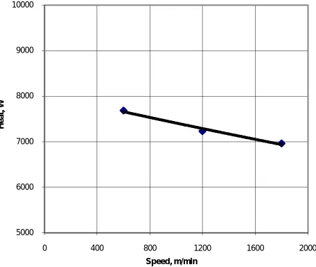
Fig. 3. Variation of heat generation with cutting speed
The temperature then would conduct through the tool, work and chip. The tool is the one, which accumulates most of heat, while chip and work surfaces in contact with the tool are continuously changing.
The effect of cutting speed on the heat generation is shown in Figure 3. It is observed that the heat generation decreases with increase in cutting speed. Other words, the sum of heat carried by the chip and heat transferred to the tool increases with increase in the cutting speed. This is a contradictory result obtained in the present work. This is in
5000 6000 7000 8000 9000 10000
0 400 800 1200 1600 2000
H
e
a
t,
W
agreement of the argument made by the other research works. Temperatures in cutting tool increase with increase in the cutting speed.
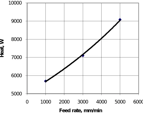
Fig.4. Variation of heat generation with feed rate
Figure 4 represents the influence of feed rate on the heat generation. The heat generation increases with increase in amount of feed rate. This behavior is believed to be caused by the built-up-edge (BUE) formation and the frictional forces. The variation of heat generation with depth of cut is represented in Figure 5 The heat generation increases with increase in depth of cut. The heat generation has been estimated using measure cutting force. It is taken as the sum of product of cutting force and cutting speed, frictional force and chip velocity, and shear force and shear velocity.
Fig. 5. Variation of heat generation with depth of cut.
The Al-si-Mg-Fe alloy gives curled or easily broken chips (Table. 5) at high cutting speeds. As the chips tended to curl considerably, the Al-si-Mg-Fe alloy experiences the plane strain machining conditions in the high-speed milling operations.
5000 6000 7000 8000 9000 10000
0 1000 2000 3000 4000 5000 6000
H
e
a
t,
W
Feed rate, mm/min
5000 6000 7000 8000 9000 10000
0 0.1 0.2 0.3 0.4 0.5 0.6 0.7
H
e
a
t,
W
Table-5.5: Size and shape of chips
Size and shape of chips
V. CONCLUSIONS
Machining induced work piece temperatures can be controlled by changing the machining parameters. The cutting temperature depends upon the depth of cuts and feed rates. The cutting temperature (heat generation) increases with an increase in the depth of cut and feed rate (figures 4 and 5). This behavior can be attributed to the precipitation hardening in the alloy on account of the formation intermetallic compounds. The presence of the precipitate phase is expected to impart thermal stability to the microstructured metallic matrix in addition to enhancing strength. The Al-si-Mg-Fe alloy gives curled or easily broken chips. The long-term temperature input will also affect the machined dimensional tolerances due to the thermal expansion of the workpiece.
REFERENCES
[1] N.A. Abukhshim , P.T Mativenga and M.A. Sheikh, “Heat generation and temperature prediction in metal cutting: A review and implications for high speed machining”, International Journal of Machine Tools & Manufacture, vol.46, pp- 782-800, 2006
[2] D.J. Richardson, M.A Keavey and F.Dailami, “Modelling of cutting induced workpiece temperatures for dry milling”, International Journal of Machine Tools & Manufacture, vol.46, pp-1139-1145, 2006.
[3] V.D. Calatoru, M.Balazinski, J.R.R. Mayer, H.Paris and G.L Esperance, “Diffsion wear mechanism during high-speed machining of 747 T7351 aluminium alloy with carbide end mills”, Wear, vol. 265, pp. 1793-1800, 2008.
[4] A. E. Dinitz, J.R. Ferreira and J.F. Silveira, “Toroidal milling of hardened SAE H13 steel”, Journal of the Brazilian Society of Mechanical Sciences & Engineering, Vol.26, No.1, pp.17-21, 2004.
[5] G. Boothroyd and W. A. Knight, Fundamentals of Machining and Machine Tools. Marcel Dekker, Inc., New York, second edition, 1989. [6] M. C. Shaw. Metal Cutting Principles, Oxford University Press, Inc., New York, second edition, 2005.
[7] T. J. Drozda and C. Wick, Machining, SME, vol. 1, Dearborn, 1983.