Response Behaviour of a Three Storied
Framed Structure with Tuned Liquid Damper
Namrata Yannawar
1, G.R.Patil
2P.G. Student, Department of Civil Engineering, Rajashri Shahu College of Engineering, Pune, Maharashtra, India1
Associate Professor, Department of Civil Engineering, Rajashri Shahu College of Engineering, Pune, Maharashtra,
India2
ABSTRACT: Tuned liquid damper is a passive damper used to control the structural vibration in structures. It is properly designed, partially filled with liquid (mostly water) is either a rigid rectangular or a cylindrical tank which is rigidly connected to the top of structure and is used as a vibration absorber. The container may be a large tank or a combination of many small tanks. Their main function is to absorb portion of the input energy associated with external dynamic excitation acting on the structure.
In this paper, a water tank is been designed which acts as tuned liquid damper. This tank is been placed at the top of a three storied framed model. The model is been experimented with tuned liquid damper and without tuned liquid damper on shake table set-up along with accelerometers connected to it. The experiment is conducted with the help of sine vibration control software. The following readings are obtained in the entire three axes. Considering the displacements in all the three directions graph has been plotted. Further, a comparison is been carried out of displacements of framed model with and without water tank at the top floor.
KEYWORDS: Excitation, Dynamic, Tuned Liquid Damper, Vibration Absorber.
I. INTRODUCTION
In olden days, engineer’s use to practice the technique which not only gave strength to the structure but also prompted greater resonance. Later, to overcome this modern engineer’s invented methods which would provide desired strength without increase in their resonance. This method aimed not only the stability of the structure but also controlled the structure during times of stress. This method is universally named as Structural Control and was first documented in early 1800s. Since then a lot of research work has been carried out and still a lot new technique using this method is been tired by a lot of scientist in different parts of the world. A professor named John Milne in 1970’s was the first to successfully use this technique. He isolated the entire structure from ground and successfully provided minimal damping to the structure.
Structural Controlling devices endure shaking effect by absorbing and dissipating seismic energy. Structural Control device are classified into 4 types:- active, hybrid, semi-active and passive. Passive device are very effective and easy to maintain. Once installed these device requires no sensors, actuators or controllers as compared to the other three categories. The only disadvantage of this device is that, after installation the device is not capable of taking any new challenges and hence in this case, it becomes necessary to replace the device.
In passive devices, oscillations of the entire mechanism affects directly to the amplitude and direction of the controlling forces. The energy required for passive systems to create the control forces in produced, not by external influences, but rather “through the motion of the mechanism during dynamic excitement”. Although there are numerous types of passive control systems, four systems are most popular: tuned mass damper (TMD), base isolation, frictional dampers, viscoelastic dampers, fluid viscous dampers and tuned liquid damper (TLD).
used in flexible and lightly damped structures.
II. EXPERIMENTALSET-UP
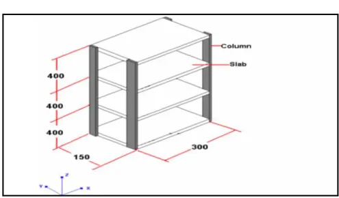
This consists of four aluminum columns and four aluminum slabs each attached to the four columns at an interval of 400 mm. The entire structure assembly (figure 1) is placed on a ED Vibration Shaker table driven by an electric motor. The ED shaker system has a capacity of 3000 kgf (Sine/Random) 6000 kgf (Shock).The Slip table is of size 600 mm X 600 mm. The RPM of the motor can be varied to achieve harmonic base motions at different frequencies.
Figure1. ED Vibration Shaker Setup
Table1. Geometric Data of the Structure
Sr
No.
Parts Dimensions in mm
Depth( D) Width( B) Length( L)
1 Column DA =3.00 BA =25.11 LA =400.00
2 Slab DB =12.70 BB =150.00 LB =300.00
Figure 2 Three-Story Building Frame used in Experiment.
Design of water tank
The fundamental sloshing frequency of a TLD, 𝑓𝑇𝐿𝐷 can be estimated using linear water sloshing frequency,
𝑓𝑤 = 1
2𝜋
𝜋𝑔 tanh
𝜋 𝐿
Where, g = acceleration due to gravity h = still water depth
L = length of tank in the direction of sloshing motion.
The sloshing frequency, 𝑓𝑇𝐿𝐷 is amplitude dependent; however, for small sloshing amplitudes we can assume
𝑓𝑇𝐿𝐷 =𝑓𝑤
III.DAMPERSTRUCTUREARRANGEMENT
The water tank designed is used as damper for the structure. The tank is placed at the top of the structure. the length of the Damper considered is 96 mm. The width of the damper considered is 100 mm. For height of water equal to 100 mm, first natural frequency of water is 2.84 rad/sec, which is equal to 99.9% of fundamental frequency of structure. Therefore height of water considered is 100 mm. The density of the water (𝜌𝑓) is 1000Kg/m3. Then the experiment is conducted with the frame is placed on the ED vibration shaker and accelerometers have been connected to each floor i.e. the base, first floor, second floor and the top floor. The accelerometer provides the displacement that occurs in the entire frame when a vibration of the shaker starts. Each accelerometer provides displacements at each floor. The frequency range starts from 2 Hz up to 40 Hz. However, the frequency in each floor hardly exceeds the frequency of 35 Hz. .
IV.EXPERIMENTALRESULTS
2 5.2 4 6.74 11 16.48 2 3 4.07 11.94 22.11 68.08
(b) (a)
Sr No.
Frequency Base First floor
Second floor
Third floor
1 4.3 4.05 4.02 3.99 8.31
2 4.4 4.05 4 3.96 7.79
Sr No.
Frequency Base First floor
Second floor
Third floor
1 4.4 6.07 8.33 8.81 19.69
2 2.9 5.95 6.17 12.5 20.67
Sr No.
Frequency Base First floor
Second floor
Third floor
1 2.9 3.89 5.57 10.01 3.7
2 4 4.03 6.77 9.25 1.69
(e) (d)
Sr No.
Frequency Base First floor
Second floor
Third floor
1 3.4 3.97 13.74 2.19 3.91
2 2.8 3.88 3.52 3.24 3.91
(f)
Fig.4. (a) Responce Behavior On X- Axis Without TLD (b) Responce Behavior On Y- Axis Without TLD (c) Responce Behavior On Z- Axis Without TLD (d) Responce Behavior On X- Axis
(e) Responce Behavior On Y- Axis (f) Responce Behavior On Z- Axis
(d) (e) (f)
In table fig. 3 (a), the vibration is considered along the length, the reading that has been shown in the table is the one which had maximum displacement. As it is seen in the table that when the TLD was not placed on the frame the displacement in the top floor was maximum as compared to other floors. In table fig. 3 (b), the vibration is considered along the breadth, the reading that has been shown in the table is the one which had maximum displacement. As it is seen in the table that when the TLD was not placed on the frame the displacement in the top floor was maximum as compared to other floors which proves the damage that will be caused at the top will be almost thrice more that the second floor and almost 90% more than the base. In table fig. 3 (c), the reading that has been shown is along the height; here the displacement is very less as compared to the other two directions. However, the displacement at the top floor is again maximum as compared to the other floors. In table fig. 3 (d), the vibration is considered along the length, the reading that has been shown in the table are the one which had maximum displacement. As it is seen in the table that when the TLD was placed on the frame the displacement in the top floor was minimum as compared to the displacement of the frame without TLD. Thus it proves that the difference in displacement is large and TLD dissipates the displacement to an extent. In table fig. 3 (f), the reading that has been shown is along the height; here the displacement is is less in the second floor it is more than the displacements of the second floor in the other two directions. However, the displacement at the top floor is again minimum as compared to the other floors. In table fig. 3 (e), the vibration is considered along the breadth, the reading that has been shown in the table is the one which had maximum displacement. As it is seen in the table that when the TLD was placed on the frame the displacement in the top floor was minimum as compared to the displacement in the frame which is without TLD which proves the damage that has occurred is very less in the entire frame and almost 90% less at the top floor. Fig. 4 a, b ,c, d, e and f shows the graphs of frequency in the x-axis versus displacement in the y-axis.
V. CONCLUSION
From the graph, it’s is seen that the displacement in the x-axis, y-axis and z-axis without water tank is more than the displacement with water tank placed at the top. Thus, it can be said that when the water tank is placed at the top of the frame and when the experiment is conducted it was proved that the water tank acts as a tuned liquid damper and it dampens the displacement to the minimum.
REFERENCES
[1] Kareem Ahsan, and Kijewski Tracy, “Mitigation of motions of tall buildings with specific examples of recent applications.” Wind and
Structures, Vol. 2, No. 3, (1999), pp. 201-251.
[2] . Spencer B.F. Jr., and Sain Michael K., “Controlling Buildings: A New Frontier in Feedback.” Special Issue of the IEEE Control Systems Magazine on Emerging Technology, Vol. 17, No. 6,(1997), pp. 19-35.
[3] Bauer H.F., “Oscillations of immiscible liquids in a rectangular container: A new damper for excited structures.” Journal of Sound and Vibration, 93(1), (1984), pp.117-133.
[4] Fujii K., Tamura Y., Sato T., Wakahara T., “Wind-induced vibration of tower and practical applications of Tuned Sloshing Damper.” Journal of
Wind Engineering and Industrial Aerodynamic-s, 33, (1990), pp. 263-272.
[5] Kareem Ahsan, “Reduction of Wind Induced Motion Utilizing a Tuned Sloshing Damper.” Journal of Wind Engineering and Industrial
Aerodynamics, 36, (1990), pp. 725-737.
[6] Sun L.M., Fujino Y., Pacheco B.M., and Chaiseri P., “Modelling of Tuned Liquid Damper (TLD).” Journal of Wind Engineering and Industrial
[9] Shang Chun-yu, and Zhao Jin-cheng, “Periods and Energy Dissipations of a Novel TLD Rectangular Tank with Angle-adjustable Baffles.” J. Shanghai Jiaotong Univ. (Sci.), 13(2), (2008), pp. 139-141.
[10] Kaneko S., and Mizota Y., “Dynamical Modelling of Deep-water-Type Cylindrical Tuned Liquid Damper with a Submerged Net,” Journal of