Data Hiding Technique with Improved
Erasability of Distortion Introduced
Himangi M. Mujumdar
1, Prof. S. B. Takale
2P.G. Student, Department of E&TC Engineering, Sinhgad College of Engineering, Pune, Maharashtra, India1
Assistant Professor, Department of E&TC Engineering, Sinhgad College of Engineering, Pune, Maharashtra, India 2
ABSTRACT: Data hiding techniques are used for data security and copyright purposes. Cryptology deals with coding and decoding secret messages. Data hiding, which is a form of Steganography, is embedding data into digital media. Reversible data hiding is embedding data into an image in reversible manner which means that the embedded data and the cover image can be recovered without any distortion. This project aims at a novel Reversible data hiding technique in encrypted images in which two tasks, data hiding and image encryption are kept separable and space required for additional data is created before image encryption. This technique uses predictive coding along with modified or improved histogram bin shifting method. Additional space required for data is created by estimating some randomly selected pixels. Advanced Encryption Standard (AES) is used for encryption of rest of the pixels. Data hiding is done with Improved or modified histogram bin shifting method to yield better quality of restored image. Objective of this project is to provide security to data to be embedded as well as to the cover image and to recover data and cover image without any distortion. As data hiding and image encryption tasks are kept separable, without the encryption key one cannot get access to original image and hence image privacy is maintained. Also, only with the data hiding key, one can embed the data in and extract out from the cover image without the knowledge of image. This technique yields improved efficiency with respect to embedding rate and Peak Signal-to-Noise-Ratio.
KEYWORDS: Embedding capacity, Embedding rate, Histogram Bin Shift, Histogram Shift, Image encryption, Image recovery, Image restoration and Reversible data hiding.
I. INTRODUCTION
Security and confidentiality of the sensitive data on the internet has become of prime importance due to tremendous growth of internet now days. To provide security to dada against unauthorized access and make it tamperproof concept of data hiding is used. Data hiding techniques are classified as reversible and irreversible. Irreversible data hiding techniques are in which contents of host media are changed which cannot be reverted back. Reversible data hiding techniques are in which host media contents are recovered exactly at the destination without any loss. Application areas are Medical, Military, Law forensics etc. Such areas highlight the importance of erasability of distortion introduced in the cover media during data embedding step. Reversible Data Hiding (RDH) techniques yield cover media as well as embedded data without any loss.
This paper proposes a novel RDH technique in which space required for additional data is created before image encryption. The technique is based on the reversal of two procedures, image encryption and vacating room to embed data. By doing so, performance is improved significantly. Performance can be considered in following aspects:
Lossless data extraction and image recovery with good PSNR values is possible.
Also these high PSNR values can be achieved with provided data embedding rates.
The data extraction and image decryption steps are separable.
II. RELATED WORK
Distortion is introduced due to embedding step. RDH technique has the ability to remove that distortion. Generally, RDH algorithms consist of two steps. The first step generates a host sequence with small entropy. The second step embeds the message in the host sequence by modifying its histogram. RDH techniques proposed till now are based on three concrete concepts as: lossless compression and appending technique [3, 4], Difference expansion [4], and histogram bin shifting [4].
[1] has proposed histogram shift technique. In [2], extension of histogram modification technique is proposed. An image shows property of correlation. Neighboring pixels in image are highly correlated, hence their pixel value difference is close to zero and theses pixel differences are used to embed data. In [5], Zhang proposed that the data hider segments the encrypted image into several non-overlapping blocks. The pixels in each block are randomly divided into two sets S0 and S1. Then the 3 LSB (least significant bits) of each pixel in set S0 are flipped if data to be embedded is „0‟ and the 3 LSB (least significant bits) of each pixel in set S1 are flipped if data to be embedded is „1‟. The disadvantage of this method is at the receiver side, image had to be decrypted first to retrieve the embedded data and hence image privacy is lost. [6] is improvement in Zhnag‟s RDH technique. A different estimation equation and side match technique is used to reduce the data recovery rate. Though this technique offers better results than Zhang‟s technique, it still has the issue of image privacy. In [7], Data extraction and Image decryption tasks are made separable. The data-hider compresses the least significant bits (LSB) of the encrypted image using a data-hiding key to create a sparse space to accommodate the additional data. In [9], author proposed higher dimensional histogram for data hiding. It uses each pixel pair and its surrounding to compute sequence of pairs of pixel difference. Using these values two dimensional histogram is generated and data is embedded in it. In this technique only one pixel in the selected pixel pair is changed by 1, its embedding capacity is low. [10] Author proposes novel concept of reserving room before encryption (RRBE). In this technique room require to hide data is emptied out before image encryption. By this technique data hiding becomes effortless as space require to hide data is already emptied out. [11] Author proposed reserving room before image encryption along with reversible separable data hiding technique.
Image entropy is the amount of information which must be coded by compression algorithm. It is maximized for encrypted images. Hence traditional RDH methods leave no spare space to embed data. All the previous techniques stated above result either into low embedding capacity [5, 6] or poor quality of the recovered image [7] with increased embedding capacity. Although errors in techniques [5, 6] can be eliminated by error correcting codes leading to the disadvantage that reduction in embedding capacity. Also, all of these methods are prone to errors in data extraction and/or image recovery. These methods try to vacate room from encrypted image to embed data. Losslessly vacating data from encrypted image is difficult and hence these techniques fail to achieve good PSNR.
The rest of this paper is organized as follows. The scheme of the proposed method is explained in Section 2. Experimental results are presented in Section 3. We conclude our paper with a discussion in Section 4.
III.PROPOSEDMETHOD
This is a novel method which enables data embedding in encrypted images. All the previous [5, 6, 7] RDH techniques spaced out additional room for data after image encryption.
guarantees no lossless recovery of data as well as cover image. Hence in this section we propose a novel RDH technique for encrypted image which reserve room for additional data before image encryption. Hence the two tasks image encryption and vacating room change their order of execution.
The proposed technique has four primary steps:
A. Vacating Room and Image Encryption: To create space for additional data and to provide privacy to image contents.
B. Data Hiding: To embed additional data for management and/or security purposes.
C. Data extraction.
D. Image Recovery.
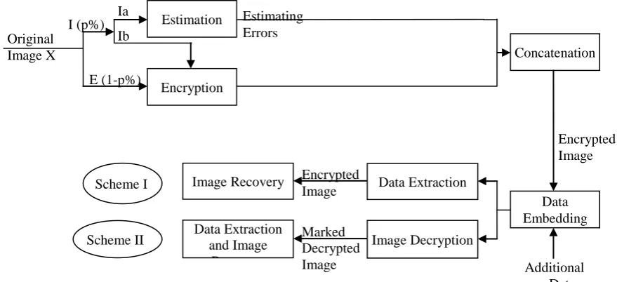
Figure 1 illustrates the idea of the proposed technique. As seen in the figure 1, estimation of some randomly selected pixels is done and errors are calculated. The histogram of these errors is shifted and space is created to accommodate additional data prior to image encryption. Also, separation of data extraction and image decryption tasks is achieved and the lossless retrieval of data and image is possible.
Fig. 1: Overview of the proposed technique
A. Vacating Room and Image Encryption
Consider the original Image X of size M×N×8-bit gray scale image. Hence pixel values X (i,j)Є[0,255], 1≤i≤M, 1≤j≤N. To create additional space for data some pixels are randomly selected and estimated using surrounding pixels. Corresponding errors are calculated by taking difference between original pixel value and estimated value. Histogram of these errors is plotted and shifted by selecting proper bin depending on length of data to be embedded. Creating space for additional data is done prior to image encryption. Random selection of pixels is done using encryption key and those pixels are specific to the encryption key used. This is required at destination side during data extraction and image restoration. When provided with the correct encryption key same pixels get selected and are used to extract data and to restore image.
p% of total pixels are selected for estimation and hence data hiding. „p‟ is determined by encryption key. These selected pixels are estimated using surrounding pixels. One may use averaging of surrounding pixel values or root mean square of surrounding pixel values. The proposed technique uses averaging of surrounding pixel. Figure 2 shows the idea of pixel estimation.
Marked Decrypted Image Encrypted Image Image Recovery
Data Extraction and Image
Recovery Scheme I
Scheme II
Concatenation
Data Embedding Data Extraction
Image Decryption
Encrypted Image
Additional Data Original
Image X
Estimating Errors Estimation
Encryption I (p%)
E (1-p%) Ia
S S S
S “C” S
S S S
Fig. 2: Scenario for estimation of selected pixel.
As shown in figure 2, C: Selected pixel position whose pixel value is to be estimated. S: Surrounding pixel positions used to estimate center pixel value.
A 3×3 mask centered at pixel „C‟ is used. The pixel value at position „C‟ is replaced by taking average of the pixel values spanned by mask. Once estimation of p% pixels is done estimating errors of these pixels are calculated by taking difference between original pixel value and estimated pixel value.
e(i,j) = X(i,j) – X‟(i,j) (1)
Where,
e(i,j) = Estimating errors,
X(i,j) = Image with original pixel values,
X(i,j) = Image with estimated pixel values.
To satisfy the formula used for averaging of surrounding pixels, one parameter „T‟ called as threshold is used. Center pixel having minimum „T‟ number of pixels in the surrounding are classified into Ia and rest pixels are classified as Ib, as shown in figure 1. Pixels belonging to only Ia are estimated and rest left as are.
The next step is replacing the gray value of selected pixels by calculated estimating errors. After replacing original pixel value of estimated pixels by estimating errors, these pixels are available to accommodate additional data.
Space required is created by Histogram shift (HS) method. In HS method histogram is generated. Ground idea behind HS is from the histogram plotted to use pixel value having zero frequency. If image is not having zero frequency point then minimum frequency point is used. In this case location map is required for exact recovery of image. Advantage of this method is such location map is not required if image has perfect zero point. Also computational overhead of this method is much less compared to other most data hiding reversible techniques. This method is very effective and simple to implement. In [12], for data embedding author has proposed standard histogram bin shifting method.
Here we see Standard Histogram Bin shifting and Improved Histogram Bin shifting methods in detail.
Standard Histogram Bin shifting:
Improved Histogram Bin shifting:
In standard HS method Data embedding point is fixed and is peak of the HS. Bins between peak and zero or minimum are shifted to create space for additional data. The quality of the recovered image depends upon the number of shifted bins. More the number of shifted bins more the distortion gets introduced. Also, not always peak point as data embedding point is required. Embedding point should depend upon the amount of data to be embedded. So embedding point should be variable depending upon the length of data to be embedded. All these drawbacks of standard histogram bin shifting method are eliminated in Improved histogram bin shifting method.
The distortion can be reduced if number of bins between embedded point and zero point are less.
Algorithm to vacate room for data:
1. Plot the histogram of estimating errors.
2. From the histogram find the zero point, ie, the pixel value having zero number of corresponding pixels say Z.
3. If zero point is absent in the histogram find the minimum point, ie, pixel value having minimum occurrence
of corresponding pixel value.
4. Choose the pixel value whose frequency of occurrence is greater than or equal to the size of the data to be
embedded say P.
5. Shift the bins between this embedding point P and zero/minimum point Z to accommodate additional data.
6. Following formulae are used to shift histogram according to data length.
𝑒′ 𝑖, 𝑗 = 𝑒 𝑖, 𝑗 + 𝑠𝑔𝑛′ 𝑒′ 𝑖, 𝑗 , 𝑖𝑓𝑒 𝑖, 𝑗 Є 𝑃, 𝑍 (2)
𝑒 𝑖, 𝑗 , 𝑂𝑡𝑒𝑟𝑤𝑖𝑠𝑒
Where e‟(i,j) represents shifted estimating errors
𝑠𝑔𝑛′ 𝑖,𝑗 = 1, 𝑊𝑒𝑟𝑒 𝑒 𝑖, 𝑗 Є 𝑃, 𝑍
0, 𝑂𝑡𝑒𝑟𝑤𝑖𝑠𝑒 (3)
If image doesn‟t contain zero frequency point then algorithm searches for minimum frequency point. Hence pixel locations of these pixels are needed to be recorded in location map for exact recovery of image. This location map is also embedded in the image using pixels belonging to E matrix. Procedure remains same.
(a) (b)
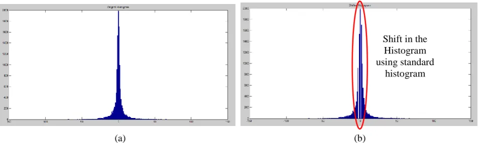
Figure 3: Standard Histogram Shift (a) Original Histogram (b) Shifted Histogram Shift in the
Histogram using standard
Figure 3 shows original histogram and shifted histogram of the standard test image lena. Here histogram is shifted using standard histogram shift method. As can be seen, histogram is shifted and space is created at the peak of the histogram.
(a) (b)
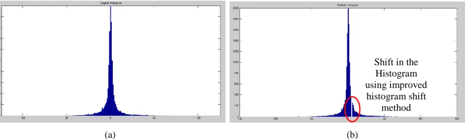
Figure 4: Improved Histogram Shift (a) Original Histogram (b) Shifted Histogram
Figure 4 shows original histogram and shifted histogram of the standard test image lena. Here histogram is shifted using improved histogram shift method. As can be seen, suitable embedding point (pixel value whose frequency of occurrence is greater than or equal to the length of the data to be embedded) is selected and histogram is shifted and space is created at the embedding point of the histogram.
B. Data Hiding:
Embedding of data into the created space with data hiding key is done as follows. P: Embedding Point
Z: Zero Point
b: Bit to be embedded
𝑒′′ 𝑖, 𝑗 = 𝑒′ 𝑖,𝑗 + 𝑏 𝑖𝑓 𝑒′ 𝑖, 𝑗 = 𝑃
𝑒′ 𝑖, 𝑗 , 𝑂𝑡𝑒𝑟𝑤𝑖𝑠𝑒 (4) Bit b can be extracted as follows
𝑏 = 0, 𝑖𝑓 𝑒′
′ 𝑖, 𝑗 = 𝑃
1, 𝑖𝑓 𝑒′′ 𝑖, 𝑗 = 𝑃 + 1 (5) Shifted error values e‟(i,j) can be extracted as follows
𝑒′ 𝑖, 𝑗 = 𝑒"(𝑖, 𝑗) 𝑖𝑓 𝑒" 𝑖, 𝑗 = 𝑃
𝑒′ 𝑖, 𝑗 − 1, 𝑖𝑓 𝑒" 𝑖, 𝑗 = 𝑃 + 1 (6)
During extraction of data and image restoration, it is necessary to know the length of the embedded data and Ia. Hence first 32 estimated errors are reserved for length of Ia and embedded data (16 for each).
To provide security to the position information of image contents, image pixels are rearranged as shown in figure 5. The image pixels are rearranged as Ia followed by Ib followed by E. Image looks like as shown in figure 5. Then image is encrypted using Advanced Encryption Standard (AES).
C. Data Extraction
Ia is put at the top of the image and first 32 errors belonging to Ia contain length of Ia and embedded data respectively. Upon acquiring data hiding key, authorized person to know embedded data, gets first 32 estimating errors and gets the length of the Ia and embedded data.
Shift in the Histogram using improved
Figure 5: Final version of encrypted image [11]
Using equation 5 embedded data can be retrieved back. To provide more security to data, prior to data embedding, data hider may encrypt the data and then embed it into image. In this case, data extractor after extracting data from image using equation 5 decrypts the data and retrieves the original data back.
D. Image Restoration
To restore the encrypted image perform following steps
Step 1: After acquiring encryption key decrypt pixels belonging to Ib and E matrix.
Step 2: Using encryption key generate p% of random locations. Place pixels in E matrix sequentially in rest 1-p% locations. By knowing the number of surrounding pixels pixel positions belonging to Ia and Ib can be easily identified and put back.
Step 3: At this stage all pixels are belonging to matrix E and Ib are correctly located to their original positions with their original pixel values. Also, pixels belonging to matrix Ia are correctly located to their original location but with estimated value. To get their original value, calculate estimating values X‟(i,j) by taking average of surrounding pixels and get marked pixel X”(i,j) as
X”(i,j) = X‟(i,j) + e‟(i,j) (7)
Where,
X”(i,j) = Marked pixel,
X‟(i,j) = Estimated pixel value by taking average of surrounding pixels e‟(i,j) = Shifted estimated errors obtained using equation (6) Step 4: Replace e‟(i,j) with X”(i,j)
Note that difference between restored image X”(i,j) and original image X‟(i,j) is imperceptible and quality of restored image is measured by using Peak Signal to Noise Ratio (PSNR).
Data Extraction and Image Restoration:
After receiving marked decrypted image content owner can extract the embedded data and recover original image. Steps are:
Step 1: Using encryption key locate pixel positions and their values belonging to matrix E.
Step 2: Using encryption key locate pixel positions belonging to Ia and calculate their estimating values by taking average of surrounding pixels. We get error values as,
e‟(i,j) = X”(i,j) - X‟(i,j) (8)
Step 3: Extract data by decoding error values with equation (5)
Estimating Errors belonging to E Estimating Errors belonging to Ia
Step 4: Recover estimating errors by
𝑒(𝑖, 𝑗) = 𝑒
′ 𝑖, 𝑗 − 𝑠𝑔𝑛′ 𝑒′(𝑖, 𝑗) ∗ 1, 𝑖𝑓𝑒 𝑖, 𝑗 Є(𝑃, 𝑍)
𝑒′(𝑖, 𝑗), 𝑂𝑡𝑒𝑟𝑤𝑖𝑠𝑒 (9) (9)
Step 5: Recover the original gray values of X(i,j) by,
X(i,j) = X‟(i,j) + e(i,j) (10) Step 6: Replace X”(i,j) by X(i,j)
IV..EXPERIMENTALRESULTS
Test image, Heart (256*256*8) is shown in fig 6 to demonstrate the feasibility of the proposed technique. Quality of recovered image is dependent on human perception. Hence the quantitative measure to measure quality of image is given by Peak Signal to Noise Ratio (PSNR). It is formulated as
PSNR = 10 ∗ log 255 2
𝑀𝑆𝐸 (8) Where,
MSE = Mean Square Error between original image and recovered image and is formulated as,
MSE = 1
𝑀∗𝑁 𝑥(𝑖, 𝑗) − 𝑥
′(𝑖, 𝑗)2 𝑁−1
𝑗 =0 𝑀−1
𝑖=0 (9) (9)
x(i,j) and x‟(i,j) are pixel values of original image and recovered image with respect to position index (i, j) respectively. Also embedding rate (ER) is defined as number of bits embedded per pixel (bpp). It is the ratio of number of bits embedded to the total number of pixels in the image,
ER = 𝑁𝑢𝑚𝑏𝑒𝑟 𝑜𝑓 𝐵𝑖𝑡𝑠 𝑒𝑚𝑏𝑒𝑑𝑑𝑒𝑑
𝑇𝑜𝑡𝑎𝑙 𝑛𝑢𝑚𝑏𝑒𝑟 𝑜𝑓 𝑃𝑖𝑥𝑒𝑙𝑠 𝑖𝑛 𝑡𝑒 𝑐𝑜𝑣𝑒𝑟 𝑖𝑚𝑎𝑔𝑒 (10)
(a) Original Image b) Encrypted Image
(c) Marked Decrypted Image with (d) Marked decrypted Image with Standard histogram shift method Improved histogram shift method and PSNR: 59.0874 and PSNR: 66.1783
Figure 6: Overview of the experimental result
Figure 6 shows (a) Original image, (b) Encrypted image, (c) Marked decrypted image with embedding rate 0.002 bpp using standard histogram shift method and PSNR as 59.0874, (d) Marked decrypted image with embedding rate 0.002 bpp using improved histogram shift method and PSNR as 66.1783. These results are obtained with parameters p and T set as, p = 10, T = 4. p determines embedding capacity while T determines estimation accuracy. Large p means large embedding capacity, so we can adapt this technique for variety of applications. For a given embedding rate we can select value of p ranging between [1, 20] by ensuring corresponding embedding capacity is larger than the required embedding rate.
The average performance of the proposed technique taken on various 25 images is listed in Table I with T = 4 and p = {20, 15, 10, 5, 1} average embedding rate of 0.0012. We have purposely selected low ER to cope up with lower p values such as p=1, so that to accommodate in the results. As shown in the Table 1, improved histogram shift method improves the quality of watermarked image. This is plotted graphically in figure 7. We can see that as the number p which is related to embedding capacity reduces, PSNR which means quality of recovered image increases.
TABLE I: AVERAGE PERFORMANCE OF THE PROPOSED TECHNIQUE
p(%) PSNR (dB)
Standard HS
PSNR (dB) Improved HS
20 56.723 63.51374
15 57.4896 64.13554
10 58.957 66.67815
5 61.533 67.24157
1 67.3 75.1817
Figure 7: Performance comparison of two techniques with respect to PSNR (dB) Versus Embedding rate (bpp)
Figure 8 shows performance of proposed techniques in terms of PSNR Vs. Embedded bits. 32 estimated pixels are required to embed lengths hence when number of bits embedded are 200, it actually requires 232 estimated pixels locations. As shown in the graph proposed technique shows better overall performance. As number of embedded bits increase, PSNR value go on decreasing, but still PSNR values are to the acceptable level.
Figure 8: PSNR (dB) Vs. Number of Embedded Bits
Also, to measure computational complexity of the proposed technique, time required for i) generation of encrypted image ii) data hiding and iii) generation of decrypted image is observed for various „p‟ which means varying embedding capacity values and found that time requirement follows order as i) encryption ii) decryption and iii) data hiding. This shows that the computational complexity for encryption and decryption is greater than data hiding process. Hence it is suggested that proposed technique is more suitable for management of encrypted images where management primarily includes data hiding and data extraction.
V. CONCLUSION
This paper proposes a novel RDH technique for encrypted image by creating space before encryption and using improved histogram bin shifting technique for data embedding. As creating room in already encrypted image is difficult this technique exploits predictive coding technique and estimation formula and creates space for additional data prior to Image encryption. This method separates image decryption and data extraction tasks and hence useful for variety of applications. With this technique privacy of embedded data as well as encrypted image is maintained. The
0 10 20 30 40 50 60 70 80
20 16 11 6 2
Improved HS
Standard HS
50 52 54 56 58 60 62 64 66
232 432 632 832 1032 1232 1432 1632 1832 2032
Improved HS
Standard HS
PSNR (dB)
person having only data hiding key can embed the data in and extract the data out without knowing the image contents and hence image contents are protected. Similarly with the encryption key only the image can be decrypted without knowing the embedded data.
REFERENCES
[1] Zhicheng Ni, Yun-Qing Shi, Nirwan Ansari and Wei Su, “Reversible Data Hiding”, IEEE Transactions On Circuits And Systems for Video Technology, Vol. 16, No. 3, March 2006.
[2] Wei-Liang Tai, Chia-Ming Yeh and Chin-Chen Chang, “Reversible Data Hiding Based on Histogram Modification of Pixel Differences”, IEEE Transactions On Circuits And Systems for Video Technology, Vol. 19, No. 6, June 2009.
[3] Jessica Fridrich, Miroslav Goljan and Rui Du, “Lossless Data Embedding For All Image Formats”, Department of Electrical Engineering, SUNY Binghamton, Binghamton, NY 13902.
[4] Xinpeng Zhang, “Reversible Data Hiding in Encrypted Image”, IEEE Signal Processing Letters, Vol. 18, No. 4, April 2011.
[5] Wien Hong, Tung-Shou Chen and Han-Yan Wu, “An Improved Reversible Data Hiding in Encrypted Images Using Side Match”, IEEE Signal Processing Letters, Vol. 19, No. 4, April 2012.
[6] Xinpeng Zhang, “Separable Reversible Data Hiding in Encrypted Image”, IEEE Transactions On Information Forensics and Security, Vol. 7, No. 2, April 2012.
[7] Masoud Nosrati, Ronak Karimi and Mehdi Hariri, “Reversible Data Hiding: Principles, Techniques, and Recent Studies”, World Applied Programming, Vol (2), Issue (5), pp. 349-353 ISSN: 2222-2510, May 2012.
[8] Available http://icetresm2015.ardigitech.in/
[9] Xiaolong Li, Weiming Zhang, Xinlu Gui and Bin Yang, “A Novel Reversible Data Hiding Scheme Based on Two-Dimensional Difference-Histogram Modification”, Transactions On Information Forensics and Security, Vol. 8, No. 7, July 2013.
[10] Kede Ma, Weiming Zhang, Xianfeng Zhao, Member, Nenghai Yu and Fenghua Li, “Reversible Data Hiding in Encrypted Images by Reserving Room Before Encryption”, IEEE Transactions On Information Forensics and Security, Vol. 8, No. 3, March 2013.
![Figure 5: Final version of encrypted image [11]](https://thumb-us.123doks.com/thumbv2/123dok_us/1668980.1209869/7.595.187.402.147.326/figure-final-version-encrypted-image.webp)

