Microcontroller Based Automatic Control
Home Appliances
Poonam Lakra1, Dr. R. P. Gupta2
Postgraduate Student, Department of Electrical Engineering (Control System), B.I.T Sindri, India1
Assistant Professor, Department of Electrical Engineering, B.I.T Sindri, Dhanbad, India2
ABSTRACT: This paper presents the “Automatic control of home appliances include Room Light and Fan Controller Using Microcontroller AT89C51” is a reliable circuit that takes over the task of controlling the room fan and room lights as well as counting number of persons / visitors in the room very accurately .When somebody enters into the room then the counter is incremented by one and the light in the room will be switched ON and when any one leaves the room then the counter is decremented by one. The speed control of fan will depend on PWM signal. It contain temperature sensor that can sense the temperature & gives the control commands for microcontroller .Then microcontroller increases as well as decreases the speed of the fan.. The total number of persons inside the room is also displayed on the liquid crystal display. The microcontroller does the above job. The main objective of control is to get the desired output and in energy conservation.
KEYWORDS- Microcontroller (AT89C51), PWM, LCD, IR Module, LM35
I. INTRODUCTION
Microcontrollers play a very vital role in the development and implementation of automation technology. Automation is the process of controlling system and information to decrease the need of human participation. Home automation represents the idea of controlling of home appliances in an integrated system. It may include the control of lighting, heating, ventilation, air-conditioning, security, and other appliances. Several sensors i.e. detector for temperature, smoke, fire, gas, PIR, light etc are used for smart home. These sensors use the input signal to control home appliances. But implementation of a unified connectivity between devices and the main controller in cost effective way is very decisive this works includes the control of switching of lights and fan according to the attendance of person, speed control of DC motor(fan) according to the variation of temperature. Thus the speed of dc motor is controlled through duty/PWM signal. In this paper, we present a flexible and reliable control scheme for controlling the dc motor and light control. Results obtained are found in good agreement with the available in data acquainted. Finally the most important section is the conclusion which concludes the purpose of this paper.
II. RELATED WORKS
In literature review, this is to be found that in recent years the energy crisis has become main problem which the whole world must confront. Home power consumption makes up the largest part of energy consumption in the world. This is to be found that the automation is the use of control systems and information technologies to reduce the need for human work in the production of goods and services. Home automation is a widely used automated system. There is an approach to control the electrical and electronic home appliances according to the attendance of persons [6][10]. Implementation of the ATmega8L microcontroller for Speed control of DC motor fed by a DC chopper has been investigated. The chopper is driven by a high frequency PWM signal. Controlling the PWM duty cycle is equivalent to controlling the motor terminal voltage, which in turn adjusts directly the motor speed [2][5].
III. PROPOSED TECHNIQUE
The project designed here is a microcontroller based embedded system. In this design, an 8-bit 8051 microcontroller is used. The microcontroller has been programmed using C language according to the required features and hence, keil has been used to compile the code written in programming language C and generate hex file, which is loaded to microcontrollers flash memory with programmer and the circuit configuration has been simulated in PROTEUS software. Speed control of dc motor using PWM technique requires some method of manipulating the width of the pulses. The system here has been designed configuring temperature and IR sensor. Temperature sensor senses the temperature of a room and it gives the microcontroller signal. The speed of fan will increase if the temperature of the room is high and decrease if the temperature of the room is low. IR sensor senses the presence of person. If there is any person in the room the light & fan will be ON after a man entering the room. The more light will be ON according to attendance of person. The light & fan will be only switched OFF until all the person in the room goes out. The total number of persons inside the room is also displayed on the liquid crystal display.
IV. SYSTEM DESIGN DISCUSSION
Software implementation: In this design, an 8-bit microcontroller is used which is of 8051family. The microcontroller is programmed using C language according to the required features and hence, Keil compiler has been used to compile the code written in programming language C and generate hex file, which is loaded to microcontroller’s flash memory with programmer and the circuit configuration has been simulated in PROTEUS software.
Fig: 1 Schematic shows the DC motor control and LEDs control simulation circuit diagram
The block diagram of the system is shown below which include power supply, AT89C51 microcontroller, temperature sensor,ADC,IR Module, DC motor, L293D driver circuit & LCD.
L293D DRIVER CIRCUIT
LCD POWER SUPPLY
TEMP.
SENSOR ADC
IR MODULE
DC MOTOR
LEDs AT89C51
COMPONENTS REQUIRED:
A. POWER SUPPLY
Five volts power supply w.r.t ground is needed for the operation of the microcontroller.
Fig: 3 Power supply unit
B. AT89C51 (microcontroller)
Micro controller (AT89C51) provides the following standard features:
4K bytes of Flash,128 bytes of RAM,32 I/O lines, Two 16-bit timer/counters, five vector two- level interrupt architecture, a full duplex serial port, on- chip oscillator and clock circuitry.
C. CRYSTAL OSCILLATOR
An electronic circuit with a precise frequency that uses the mechanical resonance of a vibrating crystal of piezoelectric material to create an electrical signal is Crystal oscillator. A crystal oscillator with 11.0592MHz frequency has been used for this work.
D. ADC (ADC0804)
The ADC0804 IC is an 8-bit parallel ADC in the family of the ADC0800 series from National Semiconductor. It works with +5volts and has a resolution of 8 bits. In the ADC0804, the conversion time varies depending on the clock signals applied to the CLK IN pin, but it cannot be faster than 110microsecond.
E. L293D
This motor driver IC is high voltage high current four channel driver designed to accept DTL or TTL logic. This can provide 600Ma output current capability per channel and providing 1.2 peak output current (non repetitive) per channel and also have internal over temperature protection. It consists of a half H-bridge to provide high current in order to drive motors. AT89C51 Port pin P2.0 is connected with EN1of L293D. When an enable input is high, the associated drivers are enabled and their outputs are active which is in phase with their inputs. When the enable input is low, those drivers are disabled, and their outputs are off and in the high impedance state.
F. TEMPERATURE SENSOR(LM35)
The temperature sensor LM35 is a precision IC temperature sensor, whose output voltage is proportional to the temperature sensor in Centigrade LM35 (-55°C to +150°C) sensor is interfaced with the microcontroller to measure the room temperature.
COMPONENTS NUMBERS RATINGS/ DESCRIPTIONS
AT89C51 1 -
Crystal oscillator 1 11.0592MHz
DC motor 1 5.9V
L293D 1 -
Capacitor 6 150pf,1000µF,1000µF,1000µF, 1000µf,10µf
Resistor 17 470ohm -2 resistor,10K-15 resistor
LM35(Temperature sensor IC) 1 (-55°C to +150°C)
IR Module 2 Record and send the actual movement
of visitor/object 7805 voltage regulator 1 Balancing the power supply
LED 4 3V,2.02V( show the output)
LCD 1 16 ×2
220V AC
MAINS
Transformer Rectifier Smoothing
filter
Regulator Regulated
G. IR SENSOR MODULE
IR (Infrared Rays) sensors work on infrared waves, the module comprises of one IR led (transmitter) and one photodiode (receiver). Module consists of 3 pines namely GND, VCC (+5V) and SIG. SIG pin provides the TTL value based on the reference voltage set. It also consists of a potentiometer which can be adjusted to vary the reference voltage hence varying its range and accuracy. This module provides a HIGH signal when a voltage greater than reference voltage is generated and a LOW (0V) signal when it is lower than reference voltage. An infrared sensor is an electronic device that radiates and senses infrared radiation with the purpose of sensing some characteristic of its surroundings.
H. DC MOTOR
A DC motor is a mechanically commutated electric motor driven by dc current. The advantages of using these types of motor over conventionally used AC motors are:
DC motors have higher controller efficiency. DC motors have typical 98% efficiency.
DC motors have better overload and peak voltage characteristics.
DC motors are widely used because its speed-torque characteristics can be varied to almost any useful form.
V. REAL IMPLEMENTATION
Hardware implementation: The programs or codes are executed and compiled. These codes are burnt by using a positron boot loader into the microcontroller. Then the hardware section of the system does the work. Hardware implementation is the hardware section of the system and the output get in that. For hardware implementation power supply unit 12V adapter, IR Module, LCD, ADC circuit with LM35, amplifier circuit, microcontroller kit is used.
Fig: 4 Hardware layouts
VI. RESULTS AND DISCUSSION
The expected results have been obtained from the data acquainted and from simulation by proteus software. A pulse with fixed frequency is generated by the microcontroller which is varied according to the temperature sensor. When the width of the pulse is maximum motor will rotate with maximum speed and at minimum pulse width motor will rotate at minimum speed. Automatic light and fan control is achieved using IR Module and temperature sensor.
SIMULATION DATA AQUAINTED
TABLE-1 Automatic LED control at counter increment values
Table-2 Automatic LED control at counter decrement values
TABLE-3 Motor direction
TABLE-4 Automatic on/off control of dc motor at counter values and speed control using pwm technique
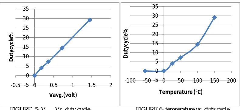
Graph plotted between Vavg. Vs. duty cycle and temperature vs. duty cycle from the above data has been obtained.
PORT PINS LEDS COUNTER VALUES OUTPUT
P2.0,P2.1,P2.2,P2.3 D1,D2,D3,D4 0 ALL OFF
P2.0 D1 1 D1 ON
P2.1 D2 3 D1 &D2 ON
P2.2 D3 5 D1,D2 & D3 ON
P2.3 D4 7 D1,D2,D3&D4 ON
PORT PINS LED COUNTER VALUES OUTPUT
P2.0,P2.1,P2.2,P2.3 D1,D2,D3,D4 0 ALL OFF
P2.0 D1 1 D1 ON D2,D3,D4 OFF
P2.1 D2 3 D1,D2 ON & D3,D4 OFF
P2.2 D3 5 D1,D2,D3 ON & D4OFF
P2.3 D4 7 D1,D2,D3,D4ON
COUNTER P0.0 MOTOR STATUS
1 or greater than 1 1 CLOCKWISE
1 or greater than1 0 ANTI CLOCKWISE
Equal to 0 1 or 0 STOP
LM35(-55°C to +150°C) (Temperature sensor)
DUTYCYCLE %
Vavg. MOTOR SPEED
-55 0 0V Zero
0 0 0V Zero
25 4 0.18V Minimum
50 7.27 0.36V Minimum
100 14.5 0.725V Medium
FIGURE .5: Vavg.. Vs. duty cycle FIGURE 6: temperature vs. duty cycle
No load output voltage waveforms at different duty cycle for Dc motor (clockwise and anticlockwise)
FIGURE7.A :( 0%Dutycycle) FIGURE 7.B: (0% Duty cycle)
FIGURE 7.C: (4% Duty cycle) FIGURE 7.D: (7% Duty cycle
-5 0 5 10 15 20 25 30 35
-0.5 0 0.5 1 1.5 2
D
u
ty
cy
cl
e%
Vavg.(volt)
-5 0 5 10 15 20 25 30 35
-100 -50 0 50 100 150 200
D
u
ty
cy
cl
e%
FIGURE 7.E: (15% Duty cycle) FIGURE 7.F: (29% Duty cycle)
no load output voltage waveform on the output terminals with 0%,4%,7% ,15% and 29% PWM in the forward and backward direction shown in Fig (7.A),(7.B),(7.C) (7.D) ,(7.E) & (7.F)respectively
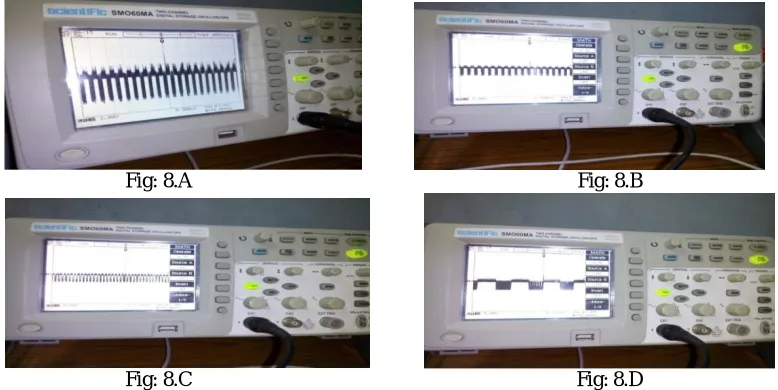
EXPERIMENTAL RESULTS HARDWARE OUTPUT WAVEFORMS
Experimental Microcontroller output PWM waveforms from pin 21 through digital oscilloscope have obtained.
Fig: 8.A Fig: 8.B
Fig: 8.C Fig: 8.D
Microcontroller output PWM waveforms from pin 21 (PORT 2.0) as shown in fig: 8.A, 8.B, 8.C &8.D
VII. CONCLUSION
acceptable as the cost is less and other features are more useful. The work can be harmonious with some other equipment to employ in case of greater place such office and industry.
VIII. ACKNOWLEDGEMENTS
This work has been supported by under the guidance of Dr. R P Gupta.
REFERENCES
1. Ganiyu, R. A., Shoewu, O., Olatinwo, S. O., Omitola, O.O, 2014, “Development of a Microcontroller-Based Motor Speed Control System Using Intel 8051”, Journal of advancement in engineering and technology, ISSN: 2348-2931.
2. Preeti, Sandeep Dogra, Rashmi Jain, 2012, “DC Drives: Microcontroller Based Control”, ISSN: 2249-8958.
3. Vaibhav Bhatia, Gavish Bhatia, 2013,”Room Temperature based Fan Speed Control System using Pulse Width Modulation Technique”, International Journal of Computer Applications (0975-8887) .
4. Usha Sharma and S.R.N. Reddy, 2012, “Design of home/office automation using wireless sensor network,” International Journal of Computer
Applications (0975-8887).
5. Snehlata SanjayThakare,Prof.Santosh Kompelli, 2014, “ Design and implementation of dc motor speed control based on pic microcontroller”
International Journal Of Engineering And Computer Science,ISSN:2319-7242
6. Mohammad Arif Hossain, Md. Nazmul Hasan,2014, “ Modern Home Automation System Based On AVR Microcontroller” International
Journal of Scientific & Engineering Research, ISSN 2229-5518
7. Inderpreet Kaur, 2010, “Microcontroller based home automation system with security,” International Journal of Advanced Computer Science
and Applications (IJACSA), pp.60-65
8. Bai, Y., & Ku, Y., (2008),”Automatic Room Light Intensity Detection and Control Using a Microprocessor and Light Sensors”, IEEE Transactions on Consumer Electronic, 1173
9. A. Alheraish, “Design and implementation of home automation system,” IEEE Transactions on Consumer Electronics, Vol. 50, pp.1087-1092,
Nov. 2004