STRUCTURAL INTEGRITY STUDY OF AN AGED
VESSEL UNDER COLD OVER-PRESSURIZATION*
REACTOR
PRESSURE
Iradj Sattari-Far, Lars Dahlberg
DET NORSKE VERITAS, P.O. Box 30234, SE-104 25 Stockholm, Sweden
ABSTRACT
The objective of this study is to develop a methodology for fracture assessment of an aged reactor under cold loading scenarios. The test program covers experiments on standard SEN(B) specimens and clad beams under uniaxial and biaxial loading. The test material was reactor steel of type A 508 Grade B, which was specially heat-treated to simulate fracture toughness properties in the aged reactor. The clad specimens were tested at room temperature, which was proven to be in the lower shelf region of the material. Detailed 3-D elastic-plastic finite element calculations are used to evaluate the outcomes of the test program. It is observed that the cladding residual stresses are of major importance in the study of a cold load event of this kind. No significant effects of shallow crack and biaxial loading are observed on cleavage fracture toughness evaluated from different clad specimens. The crack-tip constraint conditions at the deepest point of the clad beams (both under uniaxial and biaxial loading) are effectively similar to the conditions in a standard SEN(B) specimen in the lower shelf
region. While the ASME Klc reference curve is shown to be overly conservative, the Master Curve methodology
satisfactorily predicts the experimental outcomes of these tests.
1. I N T R O D U C T I O N
The background of this study goes back to a comprehensive damage tolerance study on the beltline region and the internal parts of an Swedish aged reactor, Brickstad et al [1]. The base material of the reactor is A302 Grade B with rather high contents of Cu, Ni and S elements. These elements have intensified the irradiation embrittlement in the beltline region, so that the transition ductile/brittle temperature (RTNoT) of certain welds in the beltline may be over 100 °C at the-end-of-life condition. Acceptable crack sizes and critical crack sizes were determined in the beltline region under different loading conditions. The study indicates that the limiting load case is the cold over-pressurization of the reactor, when the reactor is filled up completely with water of 40 °C and a maximum pressure of 85 bar. For this limiting load case, apart from stresses due to internal pressure and welding residual stresses, the cladding residual stresses have the major contribution. The cladding residual stresses present in the cladding when the temperature is decreased from the stress-free temperature (for instance at PWHT), and their magnitude can reach the yield strength of the cladding material at the actual temperature.
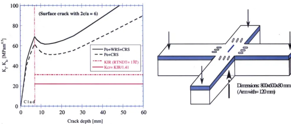
Fig. 1 shows the variation of the crack diving force Kt as a function of crack depth for a semi-elliptical surface crack
located in the axial direction in the beltline region subjected to the cold pressurization event. A fracture assessment
methodology based on the R6-method is used here, Andersson et al [2]. Two load cases are studied. In one case, it is
assumed that the crack is in a weld, thus stresses due to internal pressure (P0), welding residual stresses (WRS, assumed to be 50 MPa) and the cladding residual stresses (CRS) contribute to the crack driving force. In the second case, it is assumed that the crack is in the beltline region but not in a weld, thus only stresses due to internal pressure and the cladding residual
stresses contribute. Also shown in Fig. 1 is the fracture toughness of the base material according to ASME Ktc curve
assuming RTNoT = 117 °C. To predict the critical crack size under emergency conditions, the K1c value reduced by a safety margin of 1.41 is also shown in Fig. 1. The fracture toughness of the stainless cladding is still high (over 160 MPa~/m) at T = 40 °C. Based on the applied methodology, it is observed that the critical crack depth is equal to the thickness of the cladding layer. Accordingly, unstable crack growth may occur when the crack reaches the brittle base material of the beltline region, regardless if the crack is located in a weld or not. There are, however, three sources of uncertainty which may impact the assessment of critical defect depth in the reactor beltline region under the studied load case.
i) The fracture toughness value used in the fracture assessment is based on the ASME Ktc curve, which is based on
the reference temperature RTNor. This temperature is not determined directly from fracture toughness tests, but
from drop weight and impact tests.
* This research project is sponsored by the Swedish Nuclear Power Inspection (SKI) under contracts: SKI-14.4-0712/96- 96099 and SKI- 14.42-990163/98167.
SMiRT 16, Washington DC, August 2001 Paper # 1412
ii) The defects of this type are considered as shallow ones, which may impact the fracture toughness of the material at different conditions.
iii) Defects in reactor pressure vessels are subjected to biaxial loading, both in the directions perpendicular and parallel to the crack plane.
This study is aimed to develop a methodology to give more precise fracture assessment of the reactor pressure vessel under the cold loading event. A test program consisting of different types of cracked geometries is conducted. The test program covers SEN(B) specimens of different crack depth and clad beams containing shallow surface cracks though the cladding subjected to uniaxial and biaxial loading. The test material is rector steel of type A 508 Grade B, which is specially
heat-treated to simulate fracture toughness properties (in terms of mechanical properties and RTNor) of the reactor. Three-
dimensional elastic-plastic finite element calculations, considering the crack-tip constraint, are employed in assessments of the experimental results.
2. THE MASTER CURVE M E T H O D O L O G Y
The micromechanism of cleavage fracture exhibits a strong sensitivity to random inhomogeneities in material along the crack front. Thus, cleavage toughness data should be treated statistically rather than deterministically. It means that a given steel does not have a single value of cleavage fracture toughness at a particular temperature in the transition region; rather, it has a toughness distribution. Testing numerous specimens to obtain a statistical distribution of toughness can be expensive and time-consuming. In addition, there has been the interest to utilize small fracture specimens, e.g. Charpy size, to obtain fracture toughness data when severe limitations exist on material availability, for instance in nuclear irradiation embrittlement studies. To meet these desires, the ASTM E 1921-97 standard [3] has been developed that greatly simplifies the process of determination of fracture toughness in the transition region. The ASTM standard accounts for temperature dependence of toughness through a fracture toughness Master Curve approach developed by Wallin [4]. The temperature dependence of the fracture toughness can be determined by performing a certain amount of fracture toughness test at a given temperature. The standard covers the determination of a reference temperature To, which characterizes the fracture toughness
of ferritic steels that experience onset of cleavage cracking. By definition, To is a temperature at which the median of the Kjc
distribution from 1T size specimens will equal 100 MPa~/m. Statically elastic-plastic fracture tests are performed on standard
SEN(B) or C(T) specimens having deep notches (a/W= 0.5) to evaluate the cleavage fracture toughness Kjc.
The master curve methodology proposes to describe the cleavage fracture of the material under high constraint
conditions for which the single parameter characterization of material toughness (Kjc) holds. One important question arising
here is "How does the master curve methodology account for the constraint effects? Ruggieri et al [5] found that constraint loss leads to decrease in the To temperature. Questions such as how quantitatively consider effects of in-plane constraint (shallow cracks) and out-of-plane constraint (biaxial loading) are still open in the master curve methodology. Despite this,
application of this methodology in predictions of experimental results has shown promising results, see for instance Bass et
al [6] and Sattari-Far [7].
2.1. Crack-Tip Constraint Parameters
O'Dowd and Shih [8, 9] suggested that the crack-tip stress field in cracked body can be approximated by:
_ R e f
O'ij .~ O-ij +
a o'r ~ij .
(I)
R e f .
Here, O ij is a reference field with high stress triaxiality, which can be the HRR solution or the SSY solution assuming
plane strain conditions. Thus Q corresponds to a uniform hydrostatic shift in the stress field. A definition of Q in elastic- plastic materials using the opening stress component o00 is proposed as:
_ S S Y
Q = or°° - ° ° ° at 0 - 0 a n d r = 2 (2)
(J/a
)
'
where, o00 is the opening stress taken from the analysis of the actual geometry, a00 ssv the opening stress from the SSY analysis (with zero T-stress), and o v the yield strength.
-~ssY
_~_fe l)
(J/r )
= 2 , (3)H - crh Crh -- h - h ssY at 0 - 0 a n d - - ' C r y
O" e
where h ssv is the ratio of the hydrostatic stress to the effective stress obtained from the SSY analysis (with zero T-stress). Thus, the parameters Q and H have zero value for the reference SSY solution.
3. E X P E R I M E N T A L STUDIES
The main objective of the experimental part of this study has been to, as close as possible, simulate the fracture conditions of the beltline region. The reactor beltline region has an internal radie of 2500 mm with a nominal thickness of 125 mm. The inside of the reactor is cladded with stainless steel to a thickness of about 6 mm. The load case of concern here is the cold over-pressurization with p= 85 bar at T = 40 °C. The main features of the fracture conditions are; material properties (mechanical, physical and fracture toughness), loads (internal pressure, residual stresses) and defect geometry (surface shallow crack through the cladding).
A base material having features of
RTNor=
80 °C and cry-- 480 MPa is thought to suit the experimental objectives ofthis study. To supply test material for the experimental study of this project, 8 test plates of A 508 Class 3 reactor material were specially heat treated to introduce the required emrittlement properties corresponding to the aged reactor material.
3.1. Fracture Specimen Configurations
A basic functional requirement for configuration of test specimen is that the stress condition in the ligament would be in the same condition, which exists in the reactor beltline region. Regarding the fact that the over-pressurization scenario occurs in the lower transition region, the test specimens should also exhibit cleavage fracture event under biaxial loading at a test temperature in the lower transition region. Accordingly, fracture specimens having a cruciform-shaped geometry with sizes 800x800x70 mm having a cross section dimension of 120x80 (including 7 mm cladding) are chosen for this study. The longitudinal and transverse dimensions of the specimen were chosen to be able to impose biaxial ratio of 1:0.5 (corresponding to the internal pressure biaxial ratio in the reactor pressure vessel). To minimize diffusion of the load around the test section, three through-thickness slots of dimension 50x5 mm were cut into each arm, as shown in Fig. 2. Five cruciform clad beams and four clad beams with dimension 800x120x80 mm were prepared from the specially heat treated material. Shallow surface cracks of different depths were introduced in the clad beams by notching and prefatigue bending. Detailed information on the experimental work of this study is given in Ref. [ 11 ].
The experimental part of this study consisted of tests on single-edge notched, SEN(B), specimens under 3-point bending and tests on clad beams containing surface cracks subjected to uniaxial and biaxial loading. The SEN(B) specimens were used to evaluate fracture toughness values according to ASTM Standard E399 and also develop different master curves according to ASTM Standard E1921-97. The clad specimens were tested under uniaxial and biaxial loading to obtain cleavage fracture toughness under conditions similar to those in the reactor.
4. ANALYSIS OF T H E E X P E R I M E N T A L DATA
The general purposed finite element method (FEM) program ABAQUS [12] is used for the computations reported in this study. The pre-processor of the FEM program ANSYS [13] is used for development of the three-dimensional FEM models. The austenitic cladding and the heat-treated base material are assumed to be elastic-plastic with a piece-wise linear approximation of the hardening behavior fitted to the uniaxial test results. It is assumed that the materials obeyed the von Mises flow criterion with its associated flow rule and isotropic hardening behavior. For the analysis of the clad beams under uniaxial and biaxial loading, due to symmetry in geometry and load, only one forth of the specimens needs to be modeled. The finite element model used for the analysis of the cruciform specimens is shown in Fig. 3. The model consists of 3610 twenty-noded solid elements, fine enough around the crack front to resolve the crack-tip fields at the load level of interest. Also developed is a 3-D finite element model to determine the critical crack depth in the simulated beltline region under a cold over-pressurization scenario.
Cleavage fracture toughness data for the clad beams under biaxial and uniaxial loading were determined by finite element analysis using the load from the first pop-in in each test. The critical J-values converted to critical elastic plastic
stress-intensity factor Kjc. These results together with fracture toughness results obtained from the SEN(B) specimens and the
developed toughness curves are presented in Fig. 5. The master curves here are size-corrected for a crack front length (cfl) of 50 mm in the base material. Also shown in Fig. 5 is the ASME Ktc for RTNDz= 72 °C (obtained through impact tests). It is
observed that the ASME KIc reference curve is overly conservative in describing fracture toughness of the tests. The Master
Curve methodology gives a good prediction of fracture toughness of the tests.
5. F R A C T U R E ASSESSMENT OF T H E B E L T L I N E R E G I O N
Based on the outcomes of the experimental and analytical program of this study, a new fracture assessment is performed for the beltline region under the cold over-pressurization event. In this assessment, it is assumed that the material of the beltline region shows essentially similar fracture features as those in the heat-treated material used in the test program. The 50% master curve methodology is used here to estimate the acceptable and critical crack depths under the actual load case. The over-pressurization is assumed to be a faulted case, and thus, a safety margin of 1.41 on the fracture toughness is used to determine the acceptable defect depths. The critical defect depths are determined with reducing the safety margin to unity. The SACC program with its procedure based on the R6-method is used for this assessment [2]. Also performed are two detailed 3-D finite element analyses to check the precision of the SACC program in calculation of Kt for the actual case. In the finite element analysis, the model is assumed to be stress free at PWHT temperature (620 °C), experiencing cooling to the shut-down temperature (40 °C). Two different crack depth of 12 mm and 20 mm are studied by the finite element analysis.
Fig. 6 shows the variation of the crack diving force KI as a function of crack depth for a semi-elliptical surface crack
located in the axial direction in the beltline region subjected to the cold pressurization event. It is assumed that the crack is in a weld subjecting to stresses due to internal pressure, welding residual stresses and the cladding residual stresses. The values
of cleavage fracture toughness based on the 50% master curve Kjc and the ASME K1c curve are also shown in Fig. 6. The
master curve is size-corrected for a crack front length of 50 mm in the base material. The Kjc-value is also reduced by a factor of 1.41 in order to determine the acceptable defect depth. Also shown in Fig. 6 are the results of the finite element calculations for the two crack depths. It is observed that the ASME KIc curve methodology gives a critical defect depth of
about 3 mm for the actual case. The intersections of Krcurve with the 0.71Ksc-line and the Ksc-line give the acceptable
respective the critical crack depth for the actual case based on the master curve methodology. This leads to a value around 30
mm for the acceptable and over 40 mm for the critical defect size. As a crack of 30-mm depth with 2c/a= 6 has a crack front
length of about 100 mm in the base material, the used Ksc-value (based on 50 mm crack front length) should be size-corrected
for this amount of crack front length. This results in a surface crack with depth of 20 mm to be acceptable in the beltline region under the cold over-pressurization scenario. This result is valid under condition that fracture features in the irradiated reactor material are essentially similar with those in the heat-treated material studied here.
6. SUMMARY AND CONCLUSIONS
The major motivation of this study was to develop a methodology for fracture assessment of surface defects in an aged reactor pressure vessel under cold loading scenarios, particularly the cold over-pressurization event. A test program consisted of experiments on standard SEN(B) specimens and clad beams under uniaxial and biaxial loading was conducted during the course of this project. The structural analyses of the test program have produced very useful results, which support the following conclusions:
Cladding residual stresses are of major importance in the study of cold load events of this kind. The cladding mechanical properties are the major impacting factor in the magnitude of these stresses.
No significant effects of shallow crack and biaxial loading are observed in the clad beams tested in the experimental program of this study.
For temperature corresponding to the lower shelf region, the crack-tip constraint conditions in the clad beams, having shallow cracks under uniaxial and biaxial loading, are effectively similar to the conditions in a standard SEN(B) specimen.
The ASME Ktc reference curve is overly conservative in describing fracture toughness properties of embrittled
materials in the transition region. The Master Curve methodology provides a more precise prediction of the fracture toughness of embrittled materials.
R E F E R E N C E S
[1] Brickstad, B., Bergman, M., Dillstr~m, P., Johansson, D., Letzer, A. and W~le, J., "A damage tolerance of an old
PWR pressure vessel", ASME PVP, Fatigue and Fracture Mechanics in Pressure Vessels and Piping, Vol. 304, 1995,
pp. 45-50.
k i
[2]
[3] [4] [5] [6][7]
[8] [9] [10] [11] [12] [13]Andersson, P., Bergman, M., Brickstad, B., Dahlberg, L., Nilsson, F. and Sattari-Far, I., "A procedure for safety assessment of components with cracks-Handbook", SAQ/FoU-Report 96/08, SAQ Kontroll AB, 1996, Stockholm, Sweden.
ASTM E1921-97, "Standard test method for determination of reference temperature To for ferritic steels in the transition range", American Society of Testing and materials, 1997, Philadelphia.
Wallin, K., "Fracture toughness transition curve shape for ferritic structural steels", Proceedings of the Joint
FEFGflCF, Int. Conf. on Fract. of Eng. Materials, pp. 83-88, Singapore, August 1991.
Ruggieri, C., Dodds, R.H. and Wallin, K., "Constraint effects on reference temperature To for ferritic steels in the transition region", Eng. Fract. Mech., Vol. 60, 1998, pp. 19-36.
Bass, R., Wintle, J. And Hurst, R., "NESC-1 Project Overview", Proceeding on NESC-1 Seminar, Paris, France, March 2000.
Sattari-Far, I., "Fracture mechanics analysis of NESC-II experiments", RSE R&D Report No. 2000/04, Det Norske Veritas, 2000, Stockholm, Sweden.
O'Dowd, N.P. and Shih, C.F., "Family of crack-tip fields characterized by a triaxiality parameter-I. Structure of fields", J. Mech. Phys. Solids, Vol. 39, 1991, pp. 989-1015.
O'Dowd, N.P. and Shih, C.F., "Family of crack-tip fields characterized by a triaxiality parameter-II. Fracture applications", J. Mech. Phys. Solids, Vol. 40, 1992, pp. 939-963.
Sattari-Far, I., "Solutions of constraint parameters Q,
Qm
and H in different cracked geometries", Report No.SINTAP/SAQ/08, SAQ Kontroll AB, 1998, Stockholm, Sweden.
Sattari-Far, I., " Fracture assessment of the Oskarshamn 1 reactor pressure vessel under cold over-pressurization", RSE R&D Report No. 2001/03, Det Norske Veritas, 2000, Stockholm, Sweden.
ABAQUS, User's Manual. Version 5.8, Hibbit, Karlsson and Sorenson Inc, 1998.
ANSYS, Users Manual. Version 5.5, Swanson Analysis System Inc, 1999.
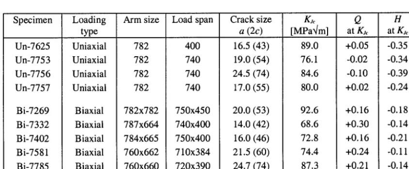
Table 1' Test results of the clad beam specimens from the experimental program (sizes in mm).
Specimen Un-7625 Un-7753 Un-7756 Un-7757 Bi-7269 Bi-7332 Bi-7402 Bi-7581 Bi-7785 Loading type Uniaxial Uniaxial Uniaxial Uniaxial Biaxial Biaxial Biaxial Biaxial Biaxial Arm size 782 782 782 782 Load span 400 740 740 740 Crack size a (2c)
16.5 (43) 19.0 (54) 24.5 (74)
17.0 (55) 782x782 787x664 784x665 760x662 760x660 750x450 740x400 750x400 710x384 720x390 20.0(53) 14.0(42) 16.0 (46)
21.5 (60) 24.7 (74) K~ [MPa~/m] 89.0 76.1 84.6 80.0 92.6 68.6 72.8 74.4 87.3
Q H
at K~ at K~
+0.05 -0.35
-0.02 -0.34
-0.10 -0.39
+0.02 -0.24
+0.16 -0.18
+0.30 -0.14
+0.16 -0.21
+0.24 -0.11
100
S ~
80
6 0 [
[1!
[ - - - ~ 1
[ ./, i
I
. . . . KIR (RTNDT=I I'(T)~_ 40 .:
20
~!
i
Clad
0 I I t'J i J I I I I I I I I I I I I I I I I t I I t I I f
0 10 20 30 40 50 60
Crack depth [mm]
1 ~ e m :
(Annvath=
la)nm
8:IkfLIk83rnnFig. 1" Variation of
KI
with crack depth for a surface crack in the beltline region under a cold over-pressurization.Fig .2: Clad beams containing surface crack under biaxial loading used in the fracture test program of this study.
A N
F r a c t u r e A n a l y s i s o f O l
O
< 1600
1200
800
400
I I I I
a -,~"
... Experiment / i
FEM . [
m~ w
./,,J
.,"
me o
Critical pop-in ,°
~/,~m • °e e °°° °
~ o " oa e
d o"
mp °m
. . . , . . . . ,-'"Test Bi-7402 (biaxial 5PB)
'_ . . . L . . . ," " " : " l I I . . . .
0 1 2 3 4 5
Deflection [mm]
Fig. 3: Finite element model used for analysis of the cruciform specimens.
2 5 0
2 0 0
,q.
o
150
~, 100
50
A U n i a x i a l c l a d b e a m 5% M a s t e r C u r v e ( c f l = 50 m m )
• B i a x i a l c l a d b e a m - - - 5 0 % M a s t e r C u r v e ( c f l = 50 m m )
o S E N ( B ) , a / W = 0.1
. . . A S M E K I c ( R T n d t = 72 °C)
~7 S E N ( B ) , a / W = 0.5
t t t t I i I O i t I I i t I I t t/ I
_
- o I _
#
_ / /
/ /
: v / i
v / /
- ~ 7
- v • i ,g
t
_- v v / l
- / #
_- /
j#
_ / o o -
_ J ,,~
' ~ •
- I ~ " B o ~
- V ~ ~ " G G G Ga'~
G G ~
_
~ / . m . m - - , , , ~ p _...=_~ . . .
I
I I I-50
s I I J I ~ I i I t ~ I i I I
0 50 100
T e m p e r a t u r e [°C]
I
150
Fig. 5: Cleavage fracture toughness obtained from different cracked geometries compared
with the master curves and ASME Klc curve.
120 I I
SACC 3D FEM
KJc (50% Master Curve, cfl= 50 ram) 0.71KJc (50% Master Curve, cfl= 50 mm)
KIc (ASME Curve for RTndt= 72 °C)
80 - i
! i i i i
i • . . .
40
Surace crack with 2c/a= 6
C l a d i
0 . . . . I . . . . I , , , , I ~ ~ t J
0 10 20 30 40
Crack depth [mm]
Fig. 6: KI as a function of crack depth in the simulated aged reactor material under the cold-