Volume 4, No. 4, March-April 2013
International Journal of Advanced Research in Computer Science
RESEARCH PAPER
Available Online at www.ijarcs.info
ISSN No. 0976-5697
Optical Watermark Based On Digital Printing
Pise Anil Audumbar*Department Of Computer Engineering, SBPCOE, Indapur, Maharastra, India,
Gupta Hitesh
Department Of Computer Engineering, PIT, Ratibad, MP, India,
Chabukswar Hrishikesh
Department Of Computer Engineering, SBPCOE, Indapur, Maharastra, India
Abstract: This paper describes a novel visual information concealment technique, referred to as optical watermarking, for the authentication of original printed documents. An optical watermark is a two-dimensional binary image. It can be of any shape and can be printed on any part of a document. The hidden information is embedded using phase modulation. Based on properties of the human visual system and modulation principle, the hidden information becomes visible to the human eyes only when a right “key” is positioned on top of the optical watermark with the right alignment. Here, “keys” play the similar role as keys in encryption, that is, to decode hidden information. Thus, with such a “lock and key” approach, it greatly improves the security level of the optical watermark. Due to its high security and tight link with electronic document systems, which requires documents to be finally printed on paper, the optical watermark has been applied to various electronic document systems. These are online ticketing, online bill of lading, and remote signing and printing of documents, where critical and unique information are embedded in watermarks and printed together with individual documents for future authentication. It has also been used in offline and traditional anti forgery applications, such as brand protection, preprinted high-value tickets, and identification documents.
Keywords: Coordinate Mapping, Secret Sharing, optical watermarking and data hiding/embedding.
I. INTRODUCTION
Digital watermarking is the process of embedding information into a digital signal. The signal may be audio, pictures or video. If the signal is copied, then the information is also carried in the copy.
In visible watermarking, the information is visible in the picture or video. Typically, the information is text or a logo which identifies the owner of the media. When a television broadcaster adds its logo to the corner of transmitted video, this is also a visible watermark.
In invisible watermarking, information is added as digital data to audio, picture or video. It cannot be visible to human eyes. An important application of invisible watermarking is to copyright protection systems, which are intended to prevent or deter unauthorized copying of digital media.
Optical watermarking present a novel and simple system aiming at overriding some practical problems when the digital watermarking techniques are applied to authenticate the printed documents. This technique differing from traditional digital watermarking in a sense that the watermark extraction is done by some optical and visual means like photocopier while no any digitization is required [1]. The system security is guaranteed by adopting content-based key share scheme originated from visual cryptography. The non-obtrusiveness effect of watermarked document is achieved by modulating the watermark into a higher resolution gratings level.
II. RELATEDWORK
Techniques for the authentication of printed documents have a long history. The mainstream of which is a traditional security printing technique and that is represented by currency note printing [2]. Security printing of currency notes uses high precision and special-purpose printing machinery. The printing resolution is as high as 4800 dots per inch (DPI) on special plates such as Intaglio plates. It uses special paper; special inks (fluorescent, photo chromic, thermo chromic, optical variable, metallic and magnetic inks) and creates special printing effects (intaglio, guilloche, electronic and metal foil stamping). The security here mainly relies on special materials used, high precision and complexity of the printing.
As advanced security printing techniques are easily accessible, this traditional technique is less reliable. Information hiding in printed documents is very different from digital watermarking. An article by R. L. van Renesse [3] provides a good review. Here, hidden images (referred to as “latent image”) embedded in a carrier screen image are invisible to the naked eye but that are visualized or decoded by means of periodic phenomena, such as an absorptive grating, a lenticular screen or the sampling of a copying system. The term “carrier screen images” is used for the printing of documents is in the form of dot arrays and that printed images are in the form of halftones. As carrier images consist of periodical arrays of screen elements, such as dots and lines, which serve as a carrier on which the encoded information is modulated.
dots by changing their position and shape. Jura’s “Invisible Personal Information (IPI)” [4], similar to “scramble indicia”, code information by modifying the positions of dots of the carrier image. Jura has now developed digital IPI using so-called “Letter- Screen”, where individual screen dots are replaced with micro text letters. Assuming that the original carrier image is printed with all dot patterns as letter “0” and the latent image is coded by changing some “0” into “1” at relevant positions. Here decoding is achieved simply by computer software by detecting all micro text “1”s.
Shimada described a very interesting work for antiphotocopying by using Tri-Branched and Divided Lines [5]. These two line patterns are microstructure lines: Tri-branched line uses three parallel thin lines to replace the original line, while divided lines use many vertical thin short line segments to replace the original line. Because of different optical properties of human eyes and photocopier machines, invisible latent images coded by tribranched and divided lines will become visible as negative images after photocopying. Here, the decoder is the photocopier.
Curry further extended the dot pattern to a new rotatable glyph shape for trusted printing applications [6]. Data coding is performed by image rendering and photocopying may blur the original image. The information hiding methods discussed above are effective in hiding information by constructing and modifying dot/ line patterns. But there are two limitations with those methods:
First, the structure of the carrier image is simply dot matrix or (straight) line gratings. This result in a limited number of different decoders and many decoders are easily available to public. In this case, the hidden information can be easily discovered and the word “hiding” becomes meaningless.
Second, because the carrier structure is known, the encoding methods can be easily discovered by using a microscope to view and analyze the dot/line patterns. An attacker can then obtain all necessary parameters and reproduce the same without much difficulty using commercially available image processing tools.
Proposed project tries to overcome these limitations by using two advance watermark layers technique.
Algorithms
III. INFORMATIONHIDINGBYPHASE
MODULATION
Proposed project establishes the mathematical framework for information hiding by using a well-known principle of modulation and the low-pass filter property of human eyes in the context of visual information hiding. This serves as the basis of the optical watermark.
Figure.1. Embedding By Phase Modulation.
A. Basic Information Carrier Structure:
The basic (or simplest) information carrier structure can be a dot array, a simple repetitive structure. The dot array can be represented by a reflectance function.
Phase Modulation to Embed Latent Images into Basic Information Carrier Structure
Proposed project shows a latent image embedding by phase modulation [7] along either the x axis or y axis as shown in Figure 1. The latent image is modulated in the direction of x axis, by shifting the image with a half period of dot matrix in the x direction.
The basic information carrier structure is generated by as shown below,
(1) The phase-shifted dot array is represented by as shown below,
Binary image hiding by phase modulation along x direction by using following
(4) Where g(x, y) is a binary image.
Proposed work has used another technique for hiding two binary images, as shown below.
Where g1(x, y) and g2(x, y) are the two binary image.
f0(x, y) is basic dot array. f1(x,y) and f2(x,y) are the dot
arrays in ‘x’ and ‘y’ directions respectively. To demodulate, following algorithm is used.
(6)
(7) Here d(x,y) is used to demodulate. Fourier series expansion is applied to analyze the modulation.
(8)
(9)
(10)
(11)
IV. ADVANCEDWATERMARKLAYERS
A. Coordinate Mapping of the Basic Watermark Layer:
In the information carrier structure for watermark layers only frequency and orientation are variable parameters. Here, proposed project applies coordinate mapping as shown in Figure 3, to watermark layers to increase the dimensionality of the information carrier structure.
Figure.2. Coordinate Mapping.
a. Algorithm for co-ordinate mapping
(12) The dot array of basic watermark layer is then mapped to the dot array of coordinate mapped watermark layer as
(13) Where sine function is used to map the coordinate.
(14)
(p, q) is used to denote the original coordinate of each dot in the watermark layer and (x, y) to denote the new coordinate of the dot after mapping. There are different coordinate mapping functions such as sine function.
B. Secret Sharing Watermark Layer:
To further improve the security level of the optical watermark proposed project makes use of the secret sharing principle [7] to increase the complexity of the decoding keys by using a random dot matrix.
A cryptographic image encoding method referred to as “visual cryptography” was presented by Adi Shamir [8]. It uses a cryptographic secret sharing theory and thus has a very high security level. Unfortunately, it is much more difficult to use in practical applications due to alignment and visibility problems during verification. Proposed project develop a secret sharing method in the context of an optical watermark. In a secret sharing watermark layer, let the information of the latent image be randomly distributed to two parts. The watermark layer will be generated based on one part, while the decoder of this watermark layer will be generated based on the other part. Hence, both the watermark layer and the decoder hold half of the information of the latent image as shown in Figure 4. The latent image is recoverable only when both the watermark layer and the decoder are present.
Figure.3. Secret Sharing Watermark Layer.
a. Algorithm for secret sharing:
We first generate two functions gw(x,y) and gd(x,y)
gw(x,y) on the dot array of the secret sharing watermark
layer with phase modulation, and modulate function gd(x,y)
on the reference line grating, which acts as a decoder, with phase modulation.
Please note that g(x,y) , r(x,y) , gw(x,y) and gd(x,y) all
take a value of either 1 or 0. We have
(15)
(16) The representation of the secret sharing watermark layer w(x,y) and its corresponding decoder d(x,y) are as follows:
(17)
(18) Implementation and Results
V. INFORMATIONHIDINGBYPHASE
MODULATION
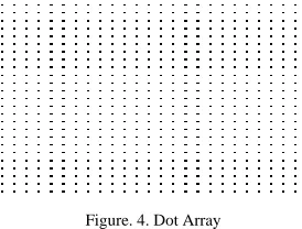
Matlab is used as platform to generate the basic dot array. Here the result is shown below.
Figure. 4. Dot Array
To read the image, imread (‘filename.jpg’) function is used. To display the image, imshow (‘filename.jpg’) function is used.
Figure. 5. Binary Image
After hiding fig3 in dot array, where phase modulated in ‘x’ direction and ‘y’ direction respectively, the result is shown below.
Figure. 6. Watermark Layer
Demodulation
Here binary image is imbedded in dot array using phase modulation with half period.
Figure. 7. Binary Image Figure. 8. Watermark Layer
The superposition of the watermarked dot array and the decoder is represented by d(x,y). The phase demodulation result is as shown below.
Figure. 9. Demodulation Result
Coordinate Mapping of the Basic Watermark Layer The basic dot array and hiding image is as shown below
Figure. 11. Binary Image
The binary image is embedded in dot array by phase modulation so that we get watermark layer. The coordinate mapping is applied on this watermark layer and get coordinate mapped watermark layer as shown below.
Figure. 12. Watermark Layer
Figure. 13. Coordinate Mapped Watermark Layer
Secret Sharing Watermark Layer
The carrier structure is random dot array and hiding image is as shown below
Figure. 14. Random Dot Array
Figure. 15. Binary Image
First, randomly distribute the binary image in two parts; the watermark layer will be generated based on one part which is shown as below
Figure. 16. Watermark Layer
While the decoder of this watermark layer will be generated based on the other part.
Figure. 17. Decoder
VI. CONCLUSION
This paper presented three types of watermark layers. They share the same information embedding method— phase modulation, while deferring by the information carrier structure. The basic watermark layer has parallel line gratings as its information carrier structure; hence, the key space is very limited. After nonlinear coordinate transformation, the key space is greatly expanded. The most complex watermark layer uses a secret sharing principle. Because of the large quantity of dots in the random information carrier structure, the key is practically unbreakable.
With a very high security optical watermark, based on digital printing, it is a new-generation anticounterfeiting technology for both physical documents and online document processing and authentications.
VII. REFERENCES
[1]. D. Hsu, “Recent development of anti-counterfeiting technology in China”, in Proc. Int. Conf. Advanced Anti-Counterfeiting Technologies, Beijing, China, Nov. 1–2, 2002, pp. 1–9.
[2]. R. R. Bernardini, R. L. van Renesse, Ed., “New security features and their impact on low-cost note readers”, in Proc. SPIE, Jun. 2004, vol. 5310, Optical Security and Counterfeit Deterrence Techniques V, pp. 52–62.
[3]. R. L. van Renesse, R. L. van Renesse, Ed., “Hidden and scrambled images: A review”, in Proc. SPIE, Apr. 2002, vol. 4677, Optical Security and Counterfeit Deterrence Techniques IV, pp. 333–348.
Techniques V, 2004, vol. 5310, Proc. SPIE-IS&T Electronic Imaging, SPIE, pp. 160–169.
[5]. K. Shimada, R. L. van Renesse, Ed., “Microstructural lines involving luminescence ”, in Opt. Security Counterfeit Deterrence Techniques V, 2004, vol. 5310, Proc. of SPIE-IS&T Electronic Imaging, SPIE, pp. 125–132.
[6]. D. N. Curry, R. L. van Renesse, Ed., “Color pictorial serpentine halftone for secure embedded data”, in Proc.
SPIE, Apr. 1998, vol. 3314, Optical Security and Counterfeit Deterrence Techniques II, pp. 309–317.
[7]. Sheng Huang and Jian Kang Wu, “Optical Watermarking for Printed Document Authentication”, IEEE Trans. on Information Forensics and Security, vol. 2, no. 2, June 2007.