Abstract— The BLDC applications are limited due to the present of torque ripples in the output during the speed control operation. This paper introduces a Proportional Integra l(PI) control approach for controlling of motor speed using CUK BLDC motor is fed with the CUK converter for speed control applications. The pulses to the CUK converter are provided through the PI controller. CUK Converter is used for low power applications and high efficient operation of SMPS power circuit. To get constant output voltage, Load current, input voltage and reference voltages are taken as feedback signals. Matlab/Simulink software is used in the execution of this project.
Index Terms— BLDC, CUK, PI Controller, Speed, Torque, VSI.
I. INTRODUCTION
Brushless DC (BLDC) motors are chosen for low power applications due to its high performance, noiseless operation, compact size and low maintenance. The BLDC motors are mostly used in the aviation, medical, aircraft, vehicular and robotic applications. Torque ripples are one of the major drawbacks of the BLDC motors which occur during variable speed operations. In recent trends due to the development of technology in power electronic devices and controllers the ease of providing controls and developing the brushless permanent magnet motors had increased. BLDC motor provides square wave signal at output which is similar to the DC motor. Permanent magnet in the motor helps to provide compact size of the motor and increases its efficiency and reliability. [1]
BLDC motor has high torque to inertia ratio, low maintenance and provides wide range of speed control. The permanent magnet in the BLDC motor acts as rotor and provides continuous flux and the stator contains three phase windings. BLDC motor has low commutation losses due to the presence of inbuilt electrical commutation. BLDC motor results in the generation of low PF and high harmonics when it is excited by uncontrolled bridge rectifiers. Hence these motors are excited by controlled AC/DC converters for
Manuscript revised on November 5, 2019 and published on November 15, 2019
Y.Divya, PG Scholar, Dept of EEE, G. Narayanamma Institute of Technology & Science (For Women), Shaikpet, Hyderabad, TS, India. E-mail: [email protected].
providing better power quality. The semiconductor devices used in the converters injects current harmonics and distorted voltage waveforms which results in low power quality and hence required high power filters.
CUK converter is one of the types of chopper circuit which has an output voltage magnitude either greater than or less than the input voltage magnitude. Moreover, the CUK converter uses coupled inductors to reduce the current ripple along with a capacitor to couple the energy. It is also inverting circuit generated from the duality principle of buck-boost converter[7].
The most important objective of the inverter is to create an ac output voltage waveform from a dc power supply at fixed or variable frequency used for high power applications .The types of waveforms generated in the inverter are required for few applications such as commutation torque control, variable speed drives, harmonic reduction, Flexible AC Transmission Systems (FACTS) devices and voltage compensators. For sinusoidal waveform, the magnitude, frequency, and phase of the inverter should be controlled. The output voltage waveform of basic inverter is mainly depending on the width of the pulse and gating signals should be sinusoidal.
The Proportional integral method is a control system that offers various benefits like stability, even for wide line and output variations, scaling back the steady state error, robustness, sensible dynamic response and easy implementation. The primary benefit of PI control schemes is its harder response to plant/system. The parameter variations that result in invariant dynamic and static response within the ideal case The PI controller to be developed for the control of CUK convertor permits to regulate the dc output voltage.
II. CUKCONVERTER
CUK converter is a DC/DC converter which steps up and steps down the voltage. It is used as both boost and buck converter which is coupled by the capacitor [8]. It functions similar to the buck-boost converter with additional control of inverting output. Capacitors are used as voltage couplers rather than inductors. Figure shown below provides the circuit diagram of CUK converter [9,10].
Simulation of Closed Loop Speed Control of CUK
Converter FED BLDC Motor with PI Controller
Fig.1 Circuit diagram of CUK converter
The average output voltage is given by For calculating L1, L2 , C1 and C2
Table 1 Specifications of CUK Converter
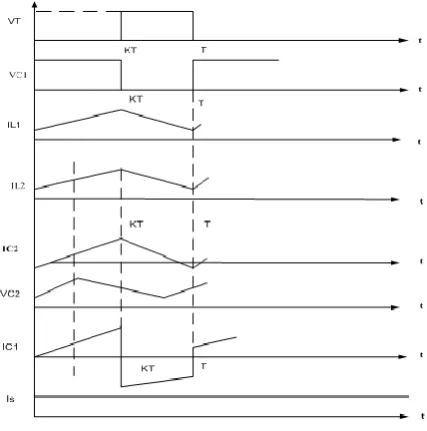
Fig.2 Waveforms of CUK converter
A. Proportional-Integral CONTROL TECHNIQUE
The PI controller calculates error between output and reference values and provides differential values for the control feedback to the CUK converter which is determined in MATLAB/Simulink. Proportional-Integral controller mode results from the combination of the proportional and also the integral mode. The PI controller has varied gains of kp and ki and produces control signals which controls the speed of the motor.
Fig 3 Block diagram of Closed loop PI Controller
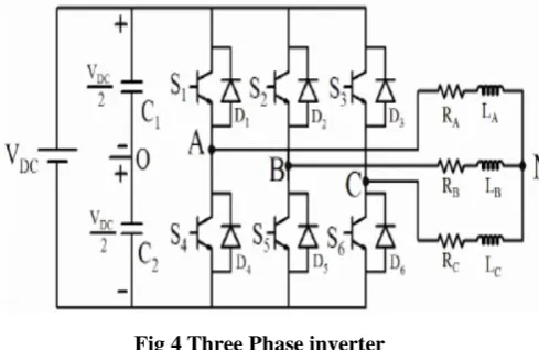
III. THREE PHASE VOLTAGE SOURCE INVERTER
Fig 4 Three Phase inverter
The voltage source inverter simply produces a square voltage waveform due to its simple turn on and off nature as different to the sinusoidal waveform that is the standard waveform of an AC power supply. By means of Fourier series, periodic waveforms are presented as the addition of the infinite series of sine waves. The sine wave that has the analogous frequency as that of the original waveform is known as primary component and other waves are called as harmonics that include in series with connected multiples of the fundamental frequency.
IV. BLDCMOTOR
The primary principle of BLDC motor is to generate a magnetic field into a rotor to rotate by using permanent magnets connected through a commutator and to produce the continuous output torque. For industrial, commercial and domestic application mainly BLDC motor is used. BLDC motors can produce continuous output torque with a three phase inverter drive. In case of BLDC motor modelling the back EMF is measured under ideal condition[5].
The final electromagnetic torque of BLDC motor is given by
(1) Due to simple operation, the centrifugal pump is
employed. In induction motor energy is converted into the kinetic energy in the form of liquid flow by accelerating the revolution.
A. Mathematical Modelling of BLDC MOTOR
The BLDC motor is designed to supply electrical commutation instead of mechanical commutation for better efficiency and extended life. In BLDC motors the commutator is being replaced by the inverter and thus it is also known as “inverted DC motors”. The rotor winding is replaced by the permanent magnets where as the input of the stator is provided through the three phase inverter [3,4]. The BLDC motor is the combination of permanent magnet motor, a stator with three phase winding and the power driving inverter circuit. Mathematical modelling includes the combination of differential equation model, transfer function model, and state-space model. The steady and dynamic characteristics are mathematically analyzed and hence provided the current and the torque variations during
V = Phase to phase voltage (Volt),
= Phase currents (Amp) of phases a, b& c respectively and
e = Back-EMF of phase a, b and c respectively. R = Per phase value of stator resistance (Ohm)and L = Per phase value of stator inductance (Henry).
= Electromagnetic torque (N-m),
The rotor reference frame equations in terms of d-q frame as shown below
Where the symbol is torque constant
The function f( ) generates trapezoidal waveform of back EMF
(9)
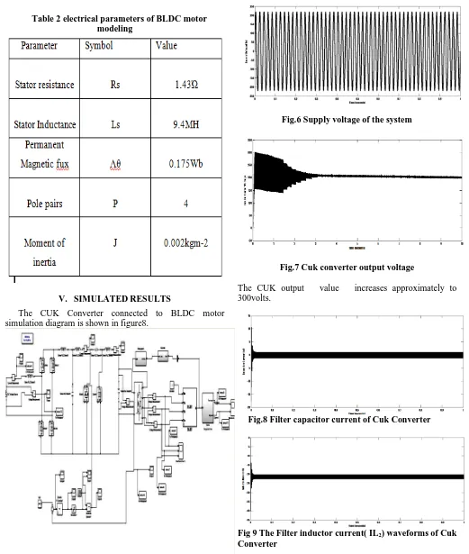
Table 2 electrical parameters of BLDC motor modeling
V. SIMULATEDRESULTS
The CUK Converter connected to BLDC motor simulation diagram is shown in figure8.
Fig 5 Modelling of CUK Converter fed BLDC Motor
Fig.6 Supply voltage of the system
Fig.7 Cuk converter output voltage
The CUK output value increases approximately to 300volts.
Fig.8 Filter capacitor current of Cuk Converter
Fig 9 The Filter inductor current( IL2) waveforms of Cuk
Fig 10 The Input inductor IL1 current of Cuk converter
Fig 11 The Input inductor IL1 current of Cuk converter
Fig.12 Three phase stator currents of BLDC motor
The rated speed of the brushless dc motor at no-load torque is equal to 1500 rpm.
Fig. 13 Speed and electromagnetic torque responses of BLDC Motor
Fig 14. Back EMF waveforms of three phase of BLDC motor
VI. CONCLUSION
Author-2 Photo
the proposed system has high speed with effectively low stator current and torque ripples.
REFERENCES
[1] Hemchand Immaneni,” Mathematical Modelling And Position Control Of Brushless Dc (Bldc) Motor” , IJERA Vol. 3,May-Jun 2013, pp.1050-1057 .
[2] Mukesh Kumar, Bhim Singh and B.P.Singh “Modeling and Simulation of Permanent Magnet Brushless Motor Drives using Simulink”, NPSC, 2011.
[3] Manali P. Chavhan , Sanjay M.Shinde,” Modeling of Brushless DC Motor with Various Loading Conditions for Electric Vehicle Application”, Volume 12, Issue 6 ,June 2016, PP.64-71.
[4] Santanu Mondal ,Arunabha Mitra, Madhurima Chattopadhyay Mathematical modeling and Simulation of Brushless DC motor with Ideal Back EMF for a Precision speed control Conference Paper August 2015.
[5] Miss Avanti B.Tayade, Modeling and Simulation of A Bldc Motor By Using Matlab/Simulation Tool, IOSR Journal of Electrical and Electronics Engineering PP 55-62,2014.
[6] R.Goutham Govind Raju, S.John Powl, A.Sathishkumar, P.Sivaprakasam Mitigation of Torque for Brushless DC Motor:
Engineering Research Volume 3, Issue 5, May-2012.
[7] Rheesabh Dwivedi, , Vinay Kumar Dwivedi, , Rahul Sharma Parametric variation analysis of CUK converter for constant voltage applications ,IJAREEIE,February2014
[8] Vashist Bist ; Bhim Singh, PFC Cuk Converter-Fed BLDC Motor Drive, IEEE Transactions on Power Electronics ( Volume: 30 , Issue: 2 , Feb. 2015 )
[9] Vaiyapuri Viswanathan, Jeevananthan.S, “Commutation Torque Ripple Reduction in BLDC Motor Using Modified SEPIC converter and Three-level NPC inverter”, IEEE Transactions on Power Electronics PP(99):1-1 · February 2017.
[10] Abin V Unni , Prof A V Unnikrishnan “PFC CUK CONVERTER FOR PMBLDCM DRIVE”, (IRJET), Volume: 03 Issue: 07 , July-2016
AUTHORSPROFILE
Y.Divya,P.G Student Power Electronics and Electrical Drives, EEE Department, G Narayanamma Institute of Technology and Science. Areas of interest include Power Electronics, Control systems, Electrical Drives..