Design, Development & Functional Validation of Magnets system
in support of 42 GHz Gyrotron in India
S. Pradhan, P. Raj, U. Prasad, M. Ghate, Y. Khristi, A. Panchal, D. Bhavsar, M. Banudha, S. Kedia, A.N. Sharma, D. Kanabar, B. Parghi
Institute for Plasma Research, Bhat, Gandhinagar, Gujarat-382428
Abstract. A multi institutional initiative is underway towards the development of 42 GHz, 200 kW gyrotron system in India under the frame work of Department of Science and Technology, Government of India. Indigenous realization comprising of design, fabrication, prototypes and functional validations of an appropriate Magnet System is one of the primary technological objective of these initiatives. The 42 GHz gyrotron magnet system comprises of a warm gun magnet, a NbTi/Cu based high homogenous superconducting cavity magnet and three warm collector magnets. The superconducting cavity magnet has been housed inside a low loss cryostat. The magnet system has been designed in accordance with gyrotron physics and engineering considerations respecting highly homogenous spatial field profile as well as maintaining steep gradient as per the compression and velocity ratios between the emission and resonator regions. The designed magnet system further ensures the co-linearity of the magnetic axis with that of the beam axis with custom winding techniques apart from a smooth collection of beam with the collector magnet profiles. The designed magnets have been wound after several R & D validations. The superconducting magnet has been housed inside a low loss designed cryostat with in-built radial and axial alignment flexibilities to certain extent. The cryostat further houses liquid helium port, liquid nitrogen ports, current communication ports, ports for monitoring helium level and other instrumentations apart from over-pressure safety intensive burst disks etc. The entire magnet system comprising of warm and superconducting magnets has been installed and integrated in the Gyrotron test set-up. The magnet system has been aligned in both warm and when the superconducting cavity magnet is cold. The integrated geometric axes have been experimentally ensured as well as the field profiles have been measured with the magnets being charged. Under experimental conditions, all magnets including the superconducting magnet have been charged to their nominal values with appropriate protection measures against the quench. This is the first time in India that a gyrotron specific magnet system with superconducting magnet has been realized.
1 Introduction
Gyrotron is a vacuum tube capable of generating high power of few millimeter-wavelength beams by electron bunching. These high power electron beams can be used to raise plasma temperature. The Electron Cyclotron Resonance Heating (ECRH) is one of the applications of gyrotron. It is basically a fast-wave microwave tube based on the principle of interaction between the gyrating beam and the transverse electric (TE) mode [1-2]. The development of gyrotron devices are focused on to produce high-power, continuous-wave, or long-pulse as a power source for Electron Cyclotron Heating (ECH). If the bunch of electron waves has correct frequency and polarization, then their energy can be transferred to the charged particles in plasma, which in turn collide with other plasma particles, thus increasing the temperature of the bulk plasma. Design, development of required technologies and its validation towards indigenous
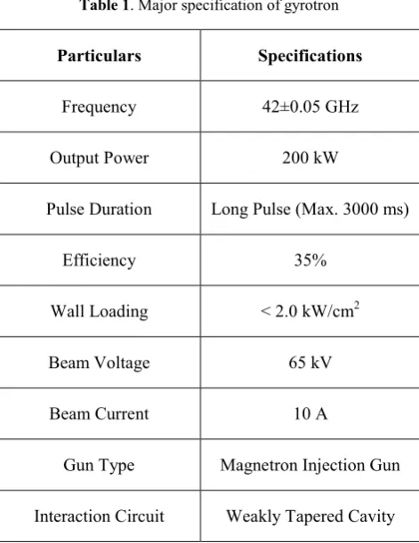
Table 1. Major specification of gyrotron
Particulars Specifications
Frequency 42±0.05 GHz
Output Power 200 kW
Pulse Duration Long Pulse (Max. 3000 ms)
Efficiency 35%
Wall Loading < 2.0 kW/cm2
Beam Voltage 65 kV
Beam Current 10 A
Gun Type Magnetron Injection Gun
Interaction Circuit Weakly Tapered Cavity
2 Design of Gyrotron Magnet System
The magnetic field required for the 42-GHz gyrotron at the interaction region is calculated to be around 1.64 ± 0.04 T for exciting TE0,3 mode during interaction. The variation in the field profile at the interaction region is ±20 mm and less than ±0.01 T (±1%) in axial direction. A very precise and homogeneous axial magnetic field is required along the path of the electron beam. For the 42 GHz gyrotron, a maximum tolerance of ±5% is allowed in the field profile along axial and radial direction except near interaction region. In gyrotron, three regions (beam trigger, beam interaction and beam collection region) are important to generate high energy electron beam. In order to meet such conditions, gyrotron magnet system consists of three kinds of magnets (Gun Magnet, Cavity Magnet and Collector Magnet) as shown in Fig.1. Gun magnet is used to optimize the quality of an electron beam by simultaneously maximizing the electron orbital-to-axial velocity ratio without reflected electrons and minimizing the velocity spread [4-5]. Cavity magnet provides very high homogeneous field which is required for the beam– wave interaction of microwave. Three collector magnets are used to optimize the beam power deposition at collector surface. Collector magnets are used to optimize the beam power deposition at collector surface. To reduce beam power density deposition at the collector, these coils are fed with alternating current and, therefore also called Saddle or sweeping coil. The design and fabrication of magnets have been done under consideration of field profile homogeneity along axial (z-direction) as well as in radial direction (r-direction). The superconducting magnets for gyrotron application employ high current
carrying and high field multi-filamentary technical superconductors, such as multi-filamentary NbTi strand that has been procured for the manufacturing of low TC solenoid cavity magnet mainly for the high field interaction region of the gyrotron [1-2]. In few cases, intermediate superconductors such as MgB2 and high TC Bismuth Strontium Calcium Copper Oxide (BSCCO) and Yttrium Barium Copper Oxide (YBCO) have also been attempted [6-7].
Fig.1. Schematic of Gyrotron System
Since the requirement of the field profile is very specific, therefore required magnetic field profile along z-direction is optimized by taking into account the magnets locations and their engineering and fabrication limitations [8-9]. Since the development of the gyrotron device is taking place for the first time in the India, it is necessary to have flexibility in all the components towards some adjustments in case of any unforeseen requirements. The magnet system is no exception. Thus, a somewhat adjustable/variable magnetic field profile is required at the time of operation for slightly tuning the magnetic peaks to get optimum output. The variation in any parameter except the magnet transport current is not feasible, once the magnets are fabricated and mounted inside the housing cryostat and oil tank. However, the gun and collectors coils currents may also have to be adjusted to maintain the beam quality and the power density deposition rate. Hence, the variation in the entire field profile is slightly nonlinear for the desired range of ±5%, which is acceptable from gyrotron physics considerations.
3 Manufacturing of Gyrotron Magnet
System (GMS)
has been used to fabricate cavity magnet. The cavity magnet has been fabricated as a combination of three solenoid magnets (a long solenoid magnet and two small magnets in Helmholtz-type configuration) at interaction region of gyro tube. This configuration has helped to get the required homogeneity of magnetic field at interaction region. The quench event of the magnet is promptly diagnosed with a smart quench detection logic and front-end electronics. The stored energy in the magnet is allowed to be distributed inside the winding pack with respect to the hot spot temperature criteria known as
passive protection. All resistive magnets (Gun Magnet or MIG Magnet and Collector Magnet) have been fabricated with enameled Cu strands. Fiber glass tapes has been used as the inter layer, inter turn and ground insulation in all the magnets. The magnet winding pack has been vacuum pressure impregnated with epoxy resin in a special vacuum pressure impregnation facility. Glass fiber (G-10) pieces are used as a support material within the magnet winding where ever required. The approximate amount of insulation will be around 20% of the total volume of the magnet.
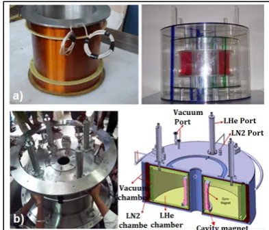
Fig. 2.a) Gyrotron magnet system b) Gun magnet c) Cavity magnet as wound d) Assembled collector magnets
3.1 Gun Magnet
Gun magnet has been fabricated with the 2.1 mm diameter copper strand. The winding pack of gun magnet has approximately 1120 turns. The detail specification and gun magnet is shown in Fig. 2b and Table.2. Gun magnet can produce magnetic field of maximum 0.03 T at current of 6.67 A.
Table 2.Technical specifications for gun magnet or MIG magnet
Description Parameters
Winding Pack inner radius 135 mm
Winding height 120 mm
Number of layers 20
Number of total turns ~1120
Conductor material Enamelled Cu
Wire strands diameter 2.1 mm
Insulation voltage capacity of
strands > 500 V
Inter turn voltage capacity 200 V
Ground insulation voltage
capacity 1 kV
3.2 Collector Magnet
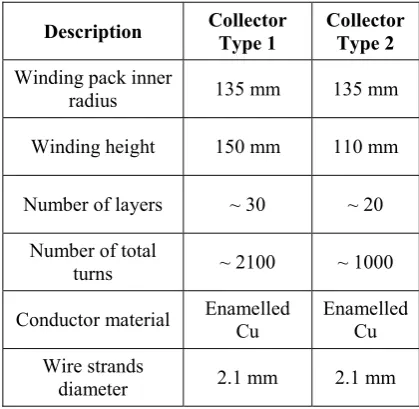
Collector magnet is manufactured using enameled copper strands of diameter 2.1 mm in layered configuration with required number of 2100 and 1000 turns respectively. For a 42 GHz gyrotron, field required at the collector magnet is ~1000 G. Collector magnet assembly consists of three individual magnets of two different types as shown in Fig.2d. The detail specification for collector magnets is given in Table 3.
Table 3.Technical specifications for collector magnet
Description Collector
Type 1
Collector Type 2
Winding pack inner
radius 135 mm 135 mm
Winding height 150 mm 110 mm
Number of layers ~ 30 ~ 20
Number of total
turns ~ 2100 ~ 1000
Conductor material Enamelled Cu
Enamelled Cu
Wire strands
Voltage capacity of
strands >500 V >500 V
Inter turn voltage
capacity > 200 V > 200 V
Ground insulation
voltage 1 kV 1 kV
Table 4. Technical specifications for cavity magnet
Description Parameters
Winding pack inner radius 105 mm
Winding height 130 mm
Number of layers (Solenoid) ~ 24
Number of total turns
(Solenoid) ~6000
Number of layers (Each
Notch) 15
Number of total turns (Each
Notch) ~630
Conductor material
Multi-filamentary
NbTi
Strand diameter 0.75 mm
Insulation voltage capacity of
strands >500 V
3.3 Cryo Magnet/Cavity Magnet and Low Loss Cryostat
The Cavity region magnet provides a very high homogenous magnetic field which is required for the electron beam interaction at bore of microwave tube. Cavity magnet consists of superconducting solenoid magnet manufactured using NbTi strands housed inside a low loss cryostat. The specification for cavity magnet is given in Table. 4. Fig. 2 C and 3 show superconducting magnet along with its positioning inside the cryostat. It has been designed to reduce loss of liquid helium. It is a multi-chamber cryostat designed to reduce heat load on superconducting magnet. The cryostat is provided with liquid nitrogen (LN2), liquid helium (LHe) filling port, current leads, vacuum ports and recovery lines for gaseous helium. [10]
This cryostat has multiple chambers for vacuum, LHe chamber and LN2 thermal shield. In Fig.3 it is shown that there are two vacuum chambers, which give a conduction and convection thermal shielding from RT thermal load. In between two vacuum chambers, there is a LN2 chamber to reduce the thermal gradient from room temperature to 77 K and 77 K to liquid helium chamber. The maximum vacuum with LN2 and LHe has been achieved up to chambers has 6 × 10⁻⁷ mbar. This arrangement provides
flexibility for pre-cooling of liquid nitrogen and liquid helium chambers by liquid nitrogen, which reduces consumption of liquid helium during GMS operation for long duration.
Fig.3.a) Superconducting cavity magnet and its prototype b) Cryostat for cavity magnet
4 Assemblies and Alignment of GMS
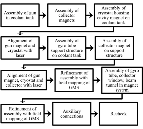
The assembly and integration of gyrotron magnet system has been carried out by adopting bottom to top approach [11]-[12]. Gun magnet is assembled on bottom side of top flange of oil tank with suitable supports. The cryostat housing Cryo-magnet is assembled on the top side of oil tank flange maintaining center of the bore hole. The supporting flange for collector magnets sub-assembly is installed at top of ring support flange. The collector magnet sub assembly is then assembled on the supporting flange. The general methodology for assembly built up for GMS with gyrotron is shown in Fig. 3. During assembly, the alignment of magnets has been carried out and measurement for the geometrical axis has been done. The assembly and alignment of GMS is validated with the help of geometrical measurements as well as magnetic field mapping in radial as well as axial direction. The fine tuning for position of various magnets in GMS is done based on experimental measurement of fields. It is ensured that magnet axis and geometric axis has been aligned within acceptable limit ± 2 mm.
Fig. 4.Typical assembly sequence for GMS
5 Performance Validations of GMS
The alignment of GMS with required accuracy has been done. The validation of its performance has to be establishing for long duration operation to generate the high power electron beam from 42 GHz gyrotron system. It is required to assure that cavity magnet has been superconducting and the voltage across cavity magnet should not exceed quench voltage (250 mV). The cavity magnet was instrumented with different type of sensors for precise monitoring, control and protection during operation of gyrotron. These sensors are LHe level sensor, hall probes, current monitoring system, quench detection and interlocks with power supply. Fig.10 shows functional block diagram of quench detection and inter-lock system. In order to optimize quench detection and protection, level of LHe and magnet quench voltages has been taken as an inter-lock signal to power supply. The superconducting cavity magnet is charged only when two necessary conditions are met.
1) LHe level should be > 10.0 inch during charging.
2) Voltage across magnet including joints and current leads should be < 250 mV.
Voltage and level signals are monitored and extended up-to quench detection system through twisted pair of copper cables over a distance of 5 m- 10 m. The level and current signal is first converted to voltage signal in quench detection system and monitored at DL750 oscilloscope. The detected magnet voltages as well as LHe level are compared to the respective threshold voltage of 250 mV and threshold time of 100 ms to activate interlock signal. All acquired signals are then digitized, monitored and stored with a DL750 scope coder based data acquisition system. The power supply for cavity magnet has been configured to an external quench protection instead of a
self-quench protection to avoid false quench trigger to a power supply system. The external quench detection system filters all the spurious high-voltage noise spikes coupled to a magnet system during operation of gyrotron system. The parameters for the quench detection and inter lock are mentioned in Table 5.
Table 5. Parameters for quench detection and interlock system
QD Parameters Values
Magnet voltage detection
Voltage threshold 250 mV
Threshold time 100 ms
Measurement accuracy 1 mV, 1 ms
LHe level detection
Level threshold 10.0 inch
Threshold time 100 ms
Measurement accuracy 0.1 inch, 1 ms
The standalone testing of individual magnets as well as testing of assembled GMS have been done at their respective current values. The inductance and resistance of individual magnet at room temperature has been measured with LCR meter (make-HIOKI 3522-50). It is shown in Table 6.
Table 6. Measured inductance and resistance value of magnets at Room Temperature (RT)
Type of magnet Inductance
(H)
Resistance (Ω)
Cavity 11.76 346
Collector Magnet-1 1.33 12.3
Collector Magnet-2 0.3 5.3
Collector Magnet-3 0.3 5.46
Gun Magnet 0.4 6.2
Dedicated individual power supplies are used for magnets with built in controller to obtain required ramp rates and current profiles. The superconducting cavity magnet is bath cooled in LHe housed inside the low loss cryostat. The performance of superconducting cavity magnet is Assembly of gun
in coolant tank
Assembly of collector magnets
Assembly of cryostat housing cavity magnet on
coolant tank
Alignment of gun magnet and
cryostat with laser
Assembly of gyro tube support structure
on coolant tank
Assembly of collector magnet
on support structure
Alignment of gun magnet, cryostat and
collector with laser
Refinement of assembly with field mapping of
GMS
Assembly of gyro tube, collector window, beam tunnel in magnet
system
Refinement of assembly with field
mapping of GMS
Auxiliary
observed experimentally at various current from 10 - 50 A at r=0 mm along z-direction. In Fig.5, peak field value near interaction region in cavity magnet is uniform from 331 mm to 371 mm along z-direction. The entire length of cryostat bore is 400 mm. With respect to assembly measurements, it starts from z=173 mm and ends at z=573 mm. From this measurement, the center position of cavity magnet has been observed at z= 353 mm, which is under acceptable deviation of ±2 mm in axial direction with respect to desired value z= 351 mm. The magnetic field profile for cavity magnet has been evaluated from bottom of gun magnet to top of the cryostat. The homogeneous and uniform magnetic field has been observed for ± 25 mm in radial (r) direction and ± 20 mm in axial (z) direction at electron beam interaction region. The helium liquid level sensor with its monitor is also connected for monitoring of liquid level in LHe chamber. After cool down of cavity magnet, it has been energized up to 50 A with ramp rate of 0.02 A/s. During charging of cavity magnet, liquid level of helium has been maintained at 10.9 inch - 11.0 inch.
Fig. 5.Field profile of cavity magnet at various current Transfer of LHe, filling of LN2 filling in 77 K shield, charging of cavity magnet, charging of resistive magnets, maintaining the liquid level and vacuum level within the cryostat during test of GMS have been shown in Fig.6. The vacuum level has been shown in Fig. 6 (b), (c) and
(d), before LHe transfer, after LHe filled and vacuum valve closed respectively. The vacuum level has got changed to 5.7 × 10⁻⁷ mbar. Magnetic field mapping has been done by energizing all magnets of GMS at their respective nominal currents. The variation of magnetic field profile in axial and radial directions has been shown in Fig.7. The field is observed to be homogeneous for ± 20 mm in axial direction at beam interaction region and ± 25 mm in radial direction throughout the length of gyro-tube. It is observed to be as per the designed requirements for optimum performance of gyrotron. The variation in peak field values near center region of cavity magnet has been measured below ±1%. This result shows that all individual magnets in GMS are aligned as per technical requirements for optimal gyrotron operation. The custom made setup having gauss meter (make- FW Bell) has been fabricated to measure magnetic field along the z-axis at r =0 mm and r =±24 mm within bore of GMS. An experimental measurement of magnetic field profile of GMS has shown in inset of Fig.8. Small deviation (within ±1%) has been observed in peak field value near center of cavity or at interaction of electron beam. This deviation is acceptable with respect to designed tolerance. All magnets have been positioned and aligned successfully as per the assembly drawings of 42 ± 0.05 GHz gyrotron system.
Fig. 6.a) LHe transfer for cavity magnet b) Vacuum at RT c) Vacuum during LHe transfer d) Vacuum when Vacuum Valve
closed
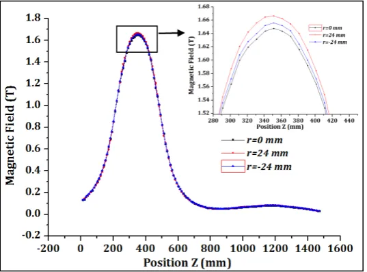
Fig.8. Simulated and experimental field profile at r=0 mm and r = ± 24 mm
Fig.9. Error between experimental and simulated values at r=0 mm and r = ± 24 mm
The experimental values also have been compared with simulated values of assembled GMS with its FEM (Fig. 8 (a), (b)). Fig. 8 shows comparison of field profile along z-direction at r=0 and r = ±24 mm. Fig. 9 shows error and error percentage at each individual axial position at r=0 and r=±24 mm. The error in magnetic field throughout the z-locations in bore of GMS has been shown in Fig, 9. In Fig. 9 (a) and (b), it is observed that the magnetic field error near beam interaction region is well below ± 1% and within ± 5% at other locations of z. The measured error field in the interaction region is ~0.3-0.7 %. As per design it should be below 1 %. The magnetic field was measured with Hall probe located at Z= ~554 mm and R = ~80 mm. At this location, the field will be around 0.3 kG at 48 A, which corresponds to 1.5 T at the cavity coil center, as shown in figure 13. Similar measurement at lower current up to 38 A is also shown in figure 11. The variation in peak magnetic field has been observed near beam interaction region ± 0.01 T, which is under the acceptable limit.
6 Operation of GMS during test
This configuration has been successfully tested and verified with multiple charging of GMS during gyrotron tube operation. The magnetic field and transport current of cavity magnet were measured with hall probe, voltage across 100 mΩ shunt resistor and respective precision electronics. The hall probe is an active sensor which operates with control current of 100 mA. Fig.11 shows the performances of electronics on measurement of transport current, magnet voltage and magnetic field at different charging conditions of the cavity magnet.
Fig.11. (a) Transport current, (b) Magnet voltage and (c) Magnetic field at different charging conditions of the cavity
magnet.
Fig.12 shows the voltage rise with respect to current confirming superconducting behavior of cavity magnet. Slow ramp rate of 0.012 A/s has been chosen to confirm the superconductivity of cavity magnet. The maximum voltage drop during charging with ramp rate of 0.012 A/s was found to be 141 mV. In Fig.13 negligible voltage fluctuation has been observed. The cavity magnet has
also been charged with 0.0209 A/s ramp rate. The quench circuit functions as designed with the cavity magnet for long duration charging of magnets. Fig. 13 shows successful long pulse operation (~ 4.5 Hrs.) with charged cavity magnet without any interruption during one of the several experimental operations of gyrotron system.
Fig.12. Current ramping in cavity magnet
Fig.13. long duration operation of GMS
7 Conclusion
field along the z-direction. GMS has been found to be suitable as well as reliable for its long duration operation to support high energy electron beam generation in gyrotron. The operation of gyrotron magnet system for long hours has been demonstrated
Acknowledgment
We acknowledge support of colleagues from Magnet Technology Development Division and SST-1 Magnet Division during this project.
References
1. S. Kedia, S. Pradhan, IEEE Trans. on App. Supercond., 20, 4, (August 2010), 2235.
2. S. Kedia, S. Pradhan, Int. Res. Report, IPR (200 8)
3. R. Prakash, DST/IPR/Gyro/12-13/ASM/0, Int. Tech. Report, IPR.
4. J. P.Anderson, M. A. Shapiro, R.J. Temkin, I. Mastovsky, and S. Cauffman, (June 2004).
5. M. Thumm, Fusion Engg. & Design, 66-68, 69-90, (2003).
6. G.B. Ferguson, N.W. Kerley and G.A. Kirby
Fusion Engg. & Design, 20, 311-316, (1993). 7. S. Sanz, IEEE Trans. on App. Supercond., (July
2007).
8. Q. Wang, Cryogenics, 47, 364–379, (2007). 9. X. Donghui, Plasma Sci. and Tech., 16 (4),
(April 2014).
10. D. Bhavsar, Internal Report, IPR.
11. P.Raj, M. Ghate, U. Prasad, Internal Report, IPR.
12. P.Raj, U. Prasad, M. Ghate, IEEE Trans. on App. Supercond., 26, 8, (December 2016), 4902607.