Available online: https://edupediapublications.org/journals/index.php/IJR/ P a g e | 1662
Block Fir Filters in Transpose Form Configuration for Area Delay
Efficient Realization of both Fixed and Reconfigurable Applications
H.Sai Shankar Nag & Mrs.T.Ranjitha Devi
M.Tech., Ph.D1M.Tech Dept of ECE, S.V.Institute of Technology College., Affiliated to JNTUA, AP, India . 2Associate Professor, Dept of ECE, S.V.Institute of Technology College., Affiliated to JNTUA, AP, India
Abstract
— Transpose form finite-impulse response (FIR) filters are inherently pipelined and support multiple constant multiplications (MCM) technique that results in significant saving of computation. However, transpose form configuration does not directly support the block processing unlike direct form configuration. In this paper, we explore the possibility of realization of block FIR filter in transpose form configuration for area-delay efficient realization of large order FIR filters for both fixed and reconfigurable applications. Based on a detailed computational analysis of transpose form configuration of FIR filter, we have derived a flow graph for transpose form block FIR filter with optimized register complexity. A generalized block formulation is presented for transpose form FIR filter. We have derived a general multiplier-based architecture for the proposed transpose form block filter for reconfigurable applications. A low-complexity design using the MCM scheme is also presented for the block implementation of fixed FIR filters. The proposed structure involves significantly less areadelay product (ADP) and less energy per sample (EPS) than the existing block implementation of direct-form structure for medium or large filter lengths, while for the short-length filters, the block implementation of direct-form FIR structure has less ADP and less EPS than the proposed structure. Application specific integrated circuit synthesis result shows that the proposed structure for block size 4 and filter length 64 involves less ADP and EPS than the best available FIR filter structure proposed for reconfigurable applications. For the same filter length and the same block size, the proposed structure involves less ADP and EPS than that of the existing direct-form block FIR structure..Key Words: Block processing, finite-impulse response (FIR) filter, reconfigurable architecture, VLSI.
I.
INTRODUCTION
Finite Impulse Response (FIR) digital filter is widely used in several digital signal processing applications, such as speech processing, loud speaker equalization, echo cancellation, adaptive noise cancellation, and various communication applications,
Available online: https://edupediapublications.org/journals/index.php/IJR/ P a g e | 1663 required to be realized by transpose form
configuration. There are some applications, such as SDR channelizer, where FIR filters need to be implemented in a reconfigurable hardware to support multi standard wireless communication. Several designs have been suggested for efficient realization of reconfigurable FIR (RFIR) using general multipliers and constant multiplication schemes. Chen and Chiueh have proposed a canonic sign digit (CSD)-based RFIR filter, where the nonzero CSD values are modified to reduce the precision of filter coefficients without significant impact on filter behaviour. But, the reconfiguration overhead is significantly large and does not provide area-delay efficient structure. The architectures are more appropriate for lower order filters and not suitable for channel filters due to their large area complexity. Constant shift method (CSM) and programmable shift method.
II. EXISTING SYSTEM
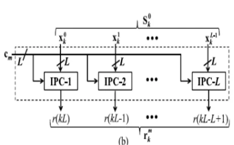
The existing structure for block FIR filter is [based on the recurrence relation of shown in Fig. 6 for the block size L = 4. It consists of one coefficient selection unit (CSU), one register unit (RU), M number of inner product units (IPUs), and one pipeline adder unit (PAU). The CSU stores coefficients of all the filters to be used for the reconfigurable application. It is implemented using N ROM LUTs, such that filter coefficients of any particular channel filter are obtained in one clock cycle, where N is the filter length. The RU receives xk during the kth cycle and produces L rows of S0k in parallel. L rows of S0kare transmitted to M IPUs of the proposed structure. The M IPUs also receive M short-weight vectors from the CSU such that during the kth cycle, the (m + 1)th IPU receives the weight vector cM−m−1 from the CSU and L rows of S0k form the RU. Each IPU performs matrix-vector product of S0k with the short-weight vector cm, and computes a block of L partial filter outputs (rmk). Therefore, each IPU performs L inner-product computations of L rows of S0k with a common weight vector cm. The structure of the (m+1)th IPU is shown in Fig. 7(b). It consists of L number of L-point inner-product cells
(IPCs). The (l+1)th IPC receives the (l+1)th row of S0k and the coefficient vector cm, and computes a partial result of inner product r (kL −l), for 0 ≤ l ≤ L − 1. Internal structure of (l + 1)th IPC for L = 4 is shown in Fig. 8(a). All the M IPUs work in parallel and produce M blocks of result (rm k ).These partial inner products are added in the PAU to obtain a block of L filter outputs. In each cycle, the proposed structure receives a block of L inputs and produces a block of L filter outputs, where the duration of each cycle is T = TM + TA + TFA log2 L, TM is one multiplier delay, TA is one adder delay, and TFA is one full-adder delay.
2.2 Drawbacks
• It provides only block performances
• High delay
• Occupies high area.
III. PROPOSED METHOD
There are several applications where the coefficients of FIR filters remain fixed, while in some other applications, like SDR channelizer that requires separate FIR filters of different specifications to extract one of the desired narrowband channels from the wideband RF front end. These FIR filters need to be implemented in a RFIR structure to support multi standard wireless communication. In this section, we present a structure of block FIR filter for such reconfigurable applications. In this section, we discuss the implementation of block FIR filter for fixed filters as well using MCM scheme.
3.1 Proposed Structure
Available online: https://edupediapublications.org/journals/index.php/IJR/ P a g e | 1664 the proposed structure. The M IPUs also receive M
short-weight vectors from the CSU such that during the kth cycle, the (m + 1)th IPU receives the weight vector cM−m−1 from the CSU and L rows of S0 k form the RU. Each IPU performs matrix-vector product of S0 k with the short-weight vector cm, and computes a block of L partial filter outputs (rm k). Therefore, each IPU performs L inner-product computations of L rows of S0 k with a common weight vector cm. In each cycle, the proposed structure receives a block of L inputs and produces a block of L filter outputs, where the duration of each cycle is T = TM + TA + TFA log2 L, TM is one multiplier delay, TA is one adder delay, and TFA is one full-adder delay.
a
Fig : proposed structures (a) Structure of RU (b) Structure of (m+1) IPU.
3.2 MCM-Based Implementation of Fixed-Coefficient FIR Filter
We discuss the derivation of MCM units for transpose form block FIR filter, and the design of proposed structure for fixed filters. For fixed-coefficient implementation, the CSU is no longer required, since the structure is to be tailored for only one given filter. Similarly, IPUs are not required. The multiplications are required to be mapped to the MCM units for a low-complexity realization. In the following, we show that the proposed formulation for MCM-based implementation of block FIR filter makes use of the symmetry in input matrix S0k to perform horizontal and vertical common sub expression elimination [17] and to minimize the number of shift-add operations in the MCM blocks.
Available online: https://edupediapublications.org/journals/index.php/IJR/ P a g e | 1665 b
is no longer required, since the structure is to be tailored for only one given filter. The recurrence relation can be expressed as
Y(z)= z−1••z−1(z−1rM−1 +rM−2 +rM−3)••+r1+r0. Where R =S0 k •C
Similarly, IPUs are not required. The multiplications are required to be mapped to the MCM units for a low-complexity realization. In the following, we show that the proposed formulation for MCM based implementation of block FIR filter makes use of the symmetry in input matrixS0k to perform horizontal and vertical common sub expression elimination and to minimize the number of shift-add operations in the MCM blocks.
3.3 Hardware and Time Complexities
The proposed structure for reconfigurable application consists of one CSU, one RU, M IPUs, and one PAU. The CSU consists of N ROM units of P words each, where P is the number of FIR filters to be implemented by the proposed reconfigurable structure. We have excluded complexity of CSU in the performance comparison, since it is common in all the RFIR structures. Each IPU is comprised of L IP cells, where each IP cell involves L multipliers and (L−1)
adders. The RU involves (L − 1) registers of B-bit width. The PAU involves (M−1) adders and the same number of registers, where each register has a width of
(B+ B_), B, and B_ respectively, being the bit width of input sample and filter coefficients. Therefore, the proposed structure involves LN multipliers, L(N− 1)
adders, and [B(N − 1) + B_(N − L)] (flip flops) FFs; and processes L samples in every cycle where the Duration of cycle period T = [TM + TA +
TFA(log2L)].
Proposed MCM Structure
3.4 Advantages
Block and higher order N processing. Less area requirement
Low delay.
IV. SIMULATION RESULTS
Available online: https://edupediapublications.org/journals/index.php/IJR/ P a g e | 1666
Area report
Power report
RTL view
V. Conclusion
Available online: https://edupediapublications.org/journals/index.php/IJR/ P a g e | 1667 generalized block formulation is presented for
transpose form block FIR filter, and based on that we have derived transpose form block filter for reconfigurable applications. We have presented a scheme to identify the MCM blocks for horizontal and vertical sub expression elimination in the proposed block FIR filter for fixed coefficients to reduce the computational complexity. Performance comparison shows that the proposed structure involves significantly less ADP and less EPS than the existing block direct-form structure for medium or large filter lengths while for the short-length filters, the existing block direct-form structure has less ADP and less EPS than the proposed structure.
REFERENCES
[1]J. G. Proakis and D. G. Manolakis, Digital Signal Processing: Principles, Algorithms and Applications. Upper Saddle River, NJ, USA:Prentice-Hall, 1996.
[2] T. Hentschel and G. Fettweis, “Software radio receivers,” in CDMA Techniques for Third Generation Mobile Systems. Dordrecht, The Netherlands: Kluwer, 1999, pp. 257–283.
[3] E. Mirchandani, R. L. Zinser, Jr., and J. B. Evans, “A new adaptive noise cancellation scheme in the presence of crosstalk [speech signals],”
IEEETrans. Circuits Syst. II, Analog Digit. Signal Process., vol. 39, no. 10, pp. 681–694, Oct. 1995. [4]D. Xu and J. Chiu, “Design of a high-order FIR
digital filtering and variable gain ranging seismic data acquisition system,” in Proc. IEEESoutheastcon, Apr. 1993, p. 1–6.
[5]J. Mitola, Software Radio Architecture: Object-Oriented Approaches to Wireless Systems Engineering. New York, NY, USA: Wiley, 2000.
[6]A. P. Vinod and E. M. Lai, “Low power and high-speed implementation of FIR filters for software defined radio receivers,” IEEE Trans. WirelessCommun., vol. 7, no. 5, pp. 1669–1675, Jul. 2006.
[7] J. Park, W. Jeong, H. Mahmoodi-Meimand, Y. Wang, H. Choo, and K. Roy, “Computation sharing programmable FIR filter for low-power and high-performance applications,” IEEE J. Solid State Circuits, vol. 39, no. 2, pp. 348–357, Feb. 2004.