Available Online atwww.ijcsmc.com
International Journal of Computer Science and Mobile Computing
A Monthly Journal of Computer Science and Information Technology
ISSN 2320–088X
IJCSMC, Vol. 4, Issue. 3, March 2015, pg.585 – 598
RESEARCH ARTICLE
Hand Palm Recognition using Combination
of Freeman Chain
Code and Texture Features with Fuzzy Logic Classifier
Zamen Fadhel Jabr
Computers Department, College of Computers and Mathematics Sciences
Thi-Qar University, Iraq
Abstract— In this paper we propose a system for hand palm recognition and analysis based on features presented by hand palm lines. The proposed system based on images taken from free Indian Institute of Technology Delhi (IITD) palmprint database of hand palm. Firstly we extracted the region of interest (ROI) from hand palm image in order to find two groups of features, the first group contain 6 texture features represented by (mean, standard deviation, smoothing, third moment, uniformity, entropy) from gray ROI whereas the second group contain 10 features extracted from (white-black) ROI, 8 of them are extracted from freeman chain code depend on 8 neighbors (0,1,2,3,4,5,6,7) the ninth and tenth features represent the area and entropy respectively. These two groups consist the vector features which contain 16 values for each ROI image which stored in our database prepared to be used in recognition phase by using fuzzy logic classifier with mamdani rule. The proposed system is applied on 120 images 60 samples are used for training and the remaining 60 samples are used for testing. The proposed system's accuracy is 90% for testing group with average of execution time is 13.6 second using Matlab environment. Thus, the recognition rate is higher when using the combination of freeman chain code and texture features with fuzzy logic classifier.
Key Words— Biometric measure, Image process, Freeman Chain Code, Texture Features, Palm Print.
I.
I
NTRODUCTIONphysical characteristics of human such as fingerprint, face, palm print, iris, or DNA to identify user and has proven to be a powerful method for authentication systems [3].
The main advantage of biometrics is that these are not prone to theft and loss, and do not rely on the memory of their users. Moreover, they do not change significantly over time and it is difficult for a person to alter own physiological biometric or imitate that of another person's. Among different biometrics, in security applications with a scope of collecting digital identity, the palm-prints are recently getting more attention among researchers [3, 4].
Palm-print recognition is a complicated visual task even for humans. The primary diffi-culty arises from the fact that different palm-print images of a particular person may vary largely, while those of different persons may not necessarily vary significantly. Moreo-ver, some aspects of palm-prints, such as variations in illumination, position, and scale, make the recognition task more complicated [6].
A palm print refers to an image acquired of the palm region of the hand. It can be either an online image (i.e. taken by a scanner, or charge-coupled device (CCD)) or offline image where the image is taken with ink and paper. The palm itself consists of principal lines, wrinkles and ridges. It differs to a fingerprint in that it also contains other infor-mation such as texture, hollows and marks which can be used when comparing one palm to another. Palm has unique distinguishing line patterns which can be used to identify people uniquely. It is a physiological biometric. A user is asked to put his/her hand in a surrounded unit having fixed illumination and a platform that restricts hand motion. It may have pegs to further fix the position of the hand. Scanners or cameras can then be used to capture the image. Palm print has high user acceptability with few hygiene based concerns characteristic of all contact based biometric. But there has been a move towards developing contactless recognition systems[7].
There are two types of palm print recognition research, 1. high resolution
2. low resolution
This paper is organized as follows: In section II, briefly preliminaries is introduced for Chain Code and Texture Features, in Section III the proposed method is presented it con-sists of read hand palm's image, preprocessing, find ROI region, feature extraction and classification stages. The experimental results are given in section IV and finally conclu-sions are reported in section V.
II.
P
RELIMINARIES1-2
Freeman Chain Code
Chain codes are one of the shape representations which are used to represent a boundary by a connected sequence of straight line segments of specified length and direction. This representation is based on 4-connectivity or 8- connectivity of the segments [9]. The direc-tion of each segment is coded by using a numbering scheme as shown in Figure2 below. Chain codes based from this scheme are known as Freeman chain codes (FCCD).
A coding scheme for line structure must satisfy three objectives [10]: a. It must faithfully preserve the information of interest.
b. It must permit compact storage and convenient for display. c. It must facilitate any required processing.
Chain codes are a linear structure that results from quantization of the trajectory traced by the centers of adjacent boundary elements in an image array. A chain code can be generated by following a boundary of an object in a clockwise direction and assigning
Figure(2) Direction numbers for (a) 4-directional chain codes, (b) 8-directional chain code Figure(1) Palm print features in (a) a high resolution image and (b) a low resolution image.
1
0 2
3
4
5 6
7
b
1
0
3 2
a
x
a direction to the segments connecting every pair of pixels. First, we pick a starting pixel location anywhere on the object boundary. The aim is to find the next pixel in the boundary [11].
There must be an adjoining boundary pixel at one of the eight locations surrounding the current boundary pixel. By looking at each of the eight adjoining pixels, we will find at least one that is also a boundary pixel. Depending on which one it is, we assign a numeric code of between 0 and 7 as already shown in Figure 2. For example, if the pixel found is located at the right of the current location or pixel, a code “0” is as-signed. If the pixel found is directly to the upper right, a code “1” is asas-signed. The pro-cess of locating the next boundary pixel and assigning a code is repeated until we came back to our first location or boundary pixel. The result is a list of chain codes showing the direction taken in moving from each boundary pixel to the next. The process of finding the boundary pixel and assigning a code is shown in Figure3 [11].
2-2
Texture Features
An important approach for describing a region in image is to quantify its texture content. A frequently used approach for texture analysis is based on statistical properties of the intensity histogram. one class of such measures is based on statistical moments. The nth moment about of the mean is given by equation1 [12].
) 1 )....( (
) (
1
0
i L
i
n i
n z m p z
m
where zi is random variable indicating intensity, p(z) is the histogram of the intensity
levels in a region, L is the number of possible intensity levels and m is the mean (aver-age) intensity. In the list below, there are some common descriptors based on statistical moments and also uniformity and entropy [12].
0 1 1 1 0
0 1 1 1 1
0 1 1 1 1
1 1 1 1 1
1 1 1 1 1
1 1 1 1 0
. .
. .
. . .
. . . .
.
. .
. . .
. . .
. . .
. . .
.
. .
. .
. . .
. . . .
.
Figure(3) a & b) A 4-connected object and its boundary; c & d) Obtaining the chain code from the object in (a & b) with (c) for 4-connected and (d) for 8-connected
2 2 3 3 3 2 3 3
0 0 0 1
0 1
1 1 2
1 3
4 4
6 6 5 6 6
0 0 0 1
2 2 2 x
y
a b
1- Mean (m) is a measure of average intensity as in equation 2.
1 0 ) 2 )....( ( L i i ip zz m
2- Standard deviation() is a measure of average contrast as in equation 3.
) 3 ....( ) ( 2 2
m z
3- Smoothness(R) shown in equation 4 measures the relative smoothness of the inten-sity in region. R is 0 for a region of constant inteninten-sity and approaches1 for regions with large excursions in the values of its intensity levels. In practice, the variance used in this measure is normalized to the range [0,1] by dividing it by (L-1)2.
) 4 )...( 1 /( 1
1 2
R
4- Third moment (m3) as shown in equation 5 measures the skewness of a histogram.
This measure is 0 for symmetric histogram , positive by histograms skewed to the right (about the mean) and negative for histogram skewed to the left. Values of this measure are brought into a range of values comparable to the other five measures by dividing m3 by (L-1)2 also, which is the same divisor we used to normalize the
variance. ) 5 )...( ( ) ( 3 1 0 3 i L i
i m p z
z m
5- Uniformity (U) as shown in equation 6 measures uniformity. this measures is max-imum when all gray levels are equal (maximally uniform) and decreases from there. ) 6 )...( ( 1 0 2 i L i z p U
6- Entropy (e) as shown in equation7 is a measure of randomness.
) 7 )...( ( log ) ( 1 0 2 i L i
i p z z p e
III.
P
ROPOSEDM
ETHODThe problem is solved in this paper is concerned with automatic recognition of person’s
palm using hand palm images which are selected from IITD palmprint database. A group
of 120 images are selected which belong to 20 person from this database with average 6
image for each person, half of these images are used for training and the other half for
testing. The system is trained by using 3 samples of each person’s hand palm image and
then tested by the 3 remaining samples. The architecture schematic of our proposed
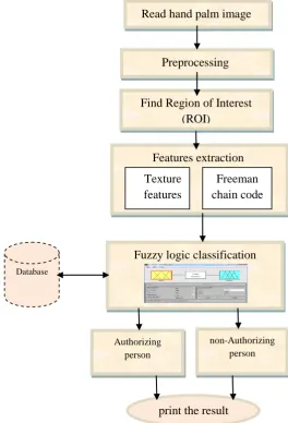
1-3 Read hand palm image
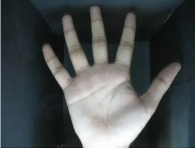
First step is read the hand palm image from IITD palmprint database. Figure5 shows one of color image used in this system during reading step, Where all images have the following properties:
1- Image format is jpeg.
2- Image Color representation is red green blue (RGB). 3- Color depth is 24.
4- Vertical and horizontal resolution is 180 dpi.
5- The width of image is 1600 pixel and height is 1200 pixel. Read hand palm image
Preprocessing
Features extraction
Texture features
Freeman chain code
Fuzzy logic classification
Database
non-Authorizing person Authorizing
person
print the result
Figure (4) architecture schematic of the proposed method Find Region of Interest
2-3 Pre-processing
This stage consists of four steps starting from a to d:
a) Convert color image to gray scale image:
A color image consists of three layers color and coordinate matrix. Color matrixes are known as Red (R), Green (G) and Blue (B). The designed system is based on gray scale images; therefore, colored image must be converted to gray scale to in-crease the speed of computation and easy in processing.
b) Filtering image
Motion filter is applied with size (55) and angle 180° in order to smooth image and increase the strength the tiny details of hand palm and decrease the intensity back-ground ( border of box which hand placed in it during capture the image) of hand palm image.
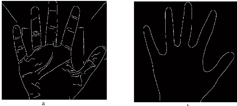
c) Edge detection
Canny filter is used to find all edges details in hand palm image where the result will be binary image with white color for edge and black color for background the threshold of canny filter is [0.04 0.10] and sigma is 3.5 this value is determined with try until canny filter reach to tiny details in hand image as shown in figure (6-a), then apply same canny filter with other value threshold is [0.1 0.4] and sigma is 90 in order to use this resulted image (after it is dilated in next system's step ) in region of interest (ROI) algorithm as it discuses in section 3-3, this image shown in figure (6-b).
d) Image Dilation
Morphological dilation process is applied on the two logical images are resulted from apply canny filter in previous step. The aim of apply morphological dilation is to connect the broken found in borders and principles lines of hand palm im-age's. Morphological dilation is applied using line shape structural element with length 3 and angle 0°, the resulted images after apply dilation are shown in figure 7(a,b).
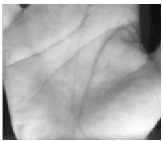
3-3 Find Region of Interest (ROI)
This stage aim to extract two ROI one from gray image by using the proposed algo-rithm1, this region (ROI1) is prepared to extract texture features from it. The other ROI is extracted from dilated image by using the proposed algorthim2, this region (ROI2) is prepared to extract freeman chain code for major principle lines from it.
Algorthim1
:
1- Remove fingers region from gray image by find the number of rows in image then extract the region from (number of rows)/2 for all column to last row for all column.
2- Apply horizontally Scan on resulted image from 1 starting from left to right and determine the first position (row, column) in which the difference in intensity
Figure (6) hand palm image after canny filter
Figure(7) dilation on hand palm image
a b
a
gray between the current pixel and next neighbors pixel column is more than 10.
3- Apply horizontally Scan in reverse order on image resulted from 2 where we start scan image from right to left and determine the first position (row ,column) in which the difference between the current pixel and past neighbors pixel column is more than 10.
4- Extract the image region of column's positions determine in step2 to step3 with all row in order to remove outer uninterested part, as shown in figure8.
Algorithm 2
1- Remove all empty row and column (zeroes rows and columns) on dilated image in figure (7-b) and determine the positions of (row and column) of first and last nonempty rows and columns to extract the region from dilated image in figure (7-a) among this positions only.
2- In the resulted image from 1 remove fingers region from binary image by find the number of rows in image then extract the region (number of rows)/2 for all column to last row for all column.
3- Remove the left and right outer of hand edge by scan the image columns's in the first ten columns and last ten columns and assign this column to zero value.
4- Extract only nonzero row and column in image resulted from 3 so we get ROI2 as shown in figure9.
4-3 Feature extraction
In this stage feature's vector contain 16 value extracted from ROI2, ROI1 as following step:
step1: The region containing longest seven lines in ROI2 is extract this line represent the principle lines, wrinkles lines in hand palm, this perform by searching in region
Figure (8) ROI1 in gray hand palm image
ROI2 about objects boundaries which it is length more than 50 pixels and zeros all ob-jects have less than this length, 10 features are extracted from this region eight of them extracted by apply freeman chain code on neighbors (0,1,2,3,4,5,6,7), this step focused on compute total number of variations pixels in freeman chain code for each one of 8 directions and place it as alone features. The ninth and tenth features are area and en-tropy respectively for region contain longest line in ROI2. Table(1) display 10 features of ROI2 for one person in our dataset in training group.
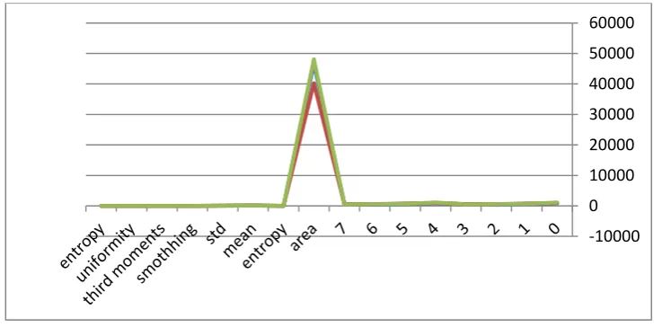
Step2:The remain six features are extracted from ROI1 which are mean, Standard de-viation, Smoothness, Third moment, Uniformity and Entropy as it is discussed in sec-tion 2-2. Table(2) display this numerical values of these six features for one person on our dataset in training group. Figure10 shows graph of 16 feature's vector for person number one.
Table(3) and table(4) display feature's vector extracted from ROI2 and ROI1 for per-son two in training phase. Figure11 shows graph of this 16 features for perper-son number two.
Image Fccd
(0) Fccd
(1) Fccd
(2) Fccd
(3) Fccd
(4) Fccd
(5) Fccd
(6) Fccd
(7) area entropy
1a.jpg 1333
900 435 110 1326 905
432 108 27789 0.332045
1b.jpg 1353
664 332 107 1355 664
330 109 28258 0.316427
1c.jpg 728
710 711 146 720 715 709 143 25182 0.342062
Entropy uniformity third
mo-ments smoothing std mean
Image
7.547656 0.00628 -3.54076 0.0638 66.56816 154.4563 1a.jpg 7.647046 0.00564 -3.1302 0.074438 72.31617 144.0193 1b.jpg 7.466373 0.006462 -3.80762 0.057914 63.22459 163.382 1c.jpg
Table (1) ten feature vector for ROI2 person one in training group
Table (2) six feature vector for ROI1 in person one in training group
Figure(10) graph of 16 feature's vector for person number one
5-3 Classification
Fuzzy logic provides a simple way to arrive at a definite conclusion based upon vague, ambiguous, imprecise, noisy, or missing input information. Furthermore, fuzzy logic emulates how a person makes decisions and performs reasoning; however, fuzzy logic does it much faster [13, 14].
There are many types of fuzzy neural network, for the forward multi-layer fuzzy neural network, the typical ones are Mamdani model, Sugeno model and Tsukamoto model. The simple and widely used Mamdani model is applied in this paper. For simplicity, as shown in figure12 we assume the and rules between input features vector which map to training vector in the fuzzy reasoning system of Mamdani model to know if the per-son who present hand palm image to the system authenticate or un-authenticate.After training phase for each person's hand palm image the system give each person solo identification number (id) this number not repeat for any person enter its data set
im--10000 0 10000 20000 30000 40000 50000 60000
image Fccd
(0) Fccd
(1) Fccd
(2) Fccd
(3) Fccd
(4) Fccd
(5) Fccd
(6) Fccd
(7) area entropy
2a.jpg 857
548 322 557 847 557
314 556 46696 0.466367
2b.jpg 890
739 572 566 885 739
577 561 40209 0.404641
2c.jpg 1154
644 543 490 1153 650
532 495 48102 0.444606
Entropy uniformity third
mo-ments smoothing std mean
image
7.191942 0.007932 -3.39935 0.05103 59.13268 143.2966 2a.jpg 7.425358 0.006558 -2.75576 0.056697 62.51636 138.5235 2b.jpg 7.116503 0.008575 -3.95784 0.05276 60.18159 148.3659 2c.jpg
Table (3) ten feature vector for ROI2 person two in training group
age to our system in futures. In testing phase the system ask from person to enter his identification number and image of his hand palm in order to test if he is the authorize person or not and to near the classification problem to nearest data set and decrease the required search time in big data set. Based on the degree of membership for each input the system decided whether the person is authenticate or not whereas threshold is placed to help the system on make decision this threshold is if the input vector match the training data set in 8 input with maximum degree of membership and the id of this person identical to the id in data set then the system result in this person is authorize to enter to the system else the person not authorize .
IV.
E
XPERIMENTALR
ESULTSMany experiments are performed to explore the possibility of the best parameters se-lection for hand palm image recognition with fuzzy logic classifier. Table (5) and table (6) display various experimental results of the multi-layer fuzzy neural network trained for the recognition of hand palm for two persons as examples. The proposed system success in recognize the hand palm image’s person. The system obtained on recogni-tion rate is 100% in training phase and rate 90% in testing phase. The system achieve using free IITD palmprint database.
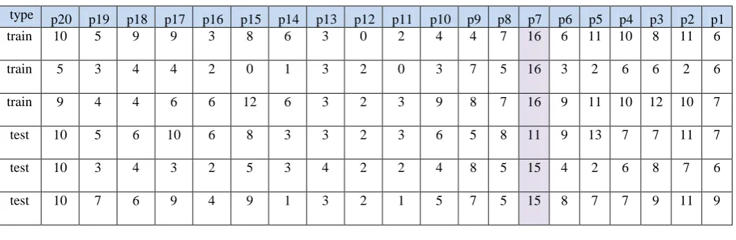
In tables bellow the symbols p1..p20 mean number of person, The number in each col-umn represent number of matching between the input vectors and the range of inputs for each person in the system in dataset with training phase which entered previously. The six row represent number of image entered to the proposed system the first three in training phase images and the last three represent testing phase images.
p1 p2 p3 p4 p5 p6 p7 p8 p9 p10 p11 p12 p13 p14 p15 p16 p17 p18 p19 p20 type 7 5 4 6 4 5 5 4 7 0 1 3 0 4 4 3 7 0 16 6 train 10 7 6 9 6 6 5 3 6 2 1 4 0 2 7 6 9 3 16 5 train 11 6 6 9 9 6 9 6 3 6 6 6 1 2 10 3 8 3 16 8 train 5 6 7 6 6 4 6 4 7 1 0 1 3 4 8 2 6 1 12 8 test 9 3 2 4 4 3 5 2 3 0 0 3 0 4 4 1 5 0 12 4 test 6 3 3 7 7 5 5 4 6 4 2 4 2 1 5 6 7 2 9 8 test
Figure (12) fuzzy logic rules for the proposed system
p1 p2 p3 p4 p5 p6 p7 p8 p9 p10 p11 p12 p13 p14 p15 p16 p17 p18 p19 p20 type 6 11 8 10 11 6 16 7 4 4 2 0 3 6 8 3 9 9 5 10 train 6 2 6 6 2 3 16 5 7 3 0 2 3 1 0 2 4 4 3 5 train 7 10 12 10 11 9 16 7 8 9 3 2 3 6 12 6 6 4 4 9 train 7 11 7 7 13 9 11 8 5 6 3 2 3 3 8 6 10 6 5 10 test 6 7 8 6 2 4 15 5 8 4 2 2 4 3 5 2 3 4 3 10 test 9 11 9 7 7 8 15 5 7 5 1 2 3 1 9 4 9 6 7 10 test
V.
C
ONCLUSIONSThe method described here is founded to be successful in dealing with tilted and forged hand palm image. The features set formulated are founded to be effective enough to capture finer variations in the hand palm image's. Freeman Chain code is used because it faithfully preserve the information of interest and it isn’t sensitive to orientation on hand and it depend on the compute the variations in direction of the pixels in bounda-ry's lines of region. Texture analysis used to find statistical properties of the intensity histogram of an image which describe quantitatively by using statistical moments. All the persons in the database are in the age group 14-56 years the method presented in this work can be an effective verification system. The proposed system can be used as security tool before enter to interest information system which can be used in banking sector and other vital organizations where users’/clients’ privacy and security are key to the success of such organizations.
R
EFERENCES[1]. M. Kabatoff, J. Dougman, BioSocieties, Pattern Recognition:Biometrics, Iden-tity and State – An Interview with John Dougman, London School of Economics and Political Science, London UK, 2008,pp. 3, 81, 86.
[2]. N.K. Ratha, J.H. Connell, and R.M. Bolle, “Enhancing Security and Privacy in Biometrics-based Authentication Systems”, IBM systems Journal, vol. 40, 2001, pp. 614-634.
[3]. M.A. Dabbah, W.L. Woo, and S.S. Dlay, “Secure Authentication for Face Recognition”, presented at Computational Intelligence in Image and Signal Pro-cessing, CIISP 2007, IEEE Symposium, 2007.
[4]. Adams Kong and David Zhang and Mohamed Kamel.A survey of palmprint recognition. Pattern Recognition, 42:1408-1418, 2009.
[5]. A. Kong and D. Zhang and G. Lu. A study of identical twins palmprint for per-sonal verification. Pattern Recognition, 39:2149-2156, 2006.
[6]. C.C. Han and H.L. Cheng and C.L. Lin and K.C. Fan. Personal authentication using palm-print features. Pattern Recognition, 36:371--381, 2003.
[7]. Krishnaveni .M, Arunpriya .C, Palmprint Identification Based on Principle Line Using Machine Learning Techniques, International Journal Of Modern Engi-neering Research (IJMER),Vol. 4, Iss. 4 , Apr. 2014.
[8]. D. Zhang,W.-K. Kong, J. You, and M.Wong, Online palmprint identification, IEEETrans.Pattern Anal. Mach. Intell., vol. 25, no. 9, pp. 1041–1050, 2003
[9]. Gonzales, R. C and Woods, R. E., Digital Image Processing.2nd Ed. Upper Saddle River, N. J.: Prentice-Hall, Inc, 2002.
[10].Freeman H, Computer Processing of Line-Drawing Images, ACM Computing Surveys, Vol. 6, No.1, 1974, pp57-97
[11].S. Madhvanath, G. Kim and V. Govindaraju, “Chaincode Contour Processing for Handwritten Word Recognition”, IEEE Transactions on Pattern Analysis and Machine ntelligence, Vol. 21, No. 9, September 1999.
[12].R. C. Gonzalez, R. E. Woods, S. L. Eddins, "Digital Image Processing Using MATLAB(R)", Prentice Hall, 2004.
[13].Simone A. Ludwig, VenkatPulimi, AndriyHnativ “Fuzzy Approach for the Evaluation of Trust and Reputation of Services” International Conference on Fuzzy Systems, pp. 115-120, 2009.
[14].Sukran YALPIR and Esra YEL “A Two Stage Fuzzy Model for Domestic Wastewater Treatment Plant Control” Water Observation and Information Sys-tems conference BALWOIS 2010.