International Journal of Research
Available at https://edupediapublications.org/journalse-ISSN: 2348-6848 p-ISSN: 2348-795X Volume 04 Issue 13
October 2017
Available online:
https://edupediapublications.org/journals/index.php/IJR/
P a g e | 100A New UPFC Approach For Power Flow Control in a Transmission Line
Bussary Shwetha & B.Bhaskar
1M.Tech Student,PE, Chaitanya Institute Of Technology And Science, Warangal, Telangana,India 2Asst.Prof, Dept of EEE Chaitanya Institute Of Technology And Science, Warangal, Telangana,India
E-mail: shwetha.bussary@gmail.com
ABSTRACT:This paper concentrates on fact tool UPFC which is used for powerflow manage in thetransmission side. With the developing demand of energy, it isn't always possible to erect new lines to face thesituation. bendy AC Transmission system (facts) makes use of the thyristor controlled gadgets and optimallyutilizes the existing transmission community. one of such device is Unified electricity flow Controller (UPFC) onwhich the emphasis is given in this present paintings. actual, reactive electricity, and voltage balance of the unifiedpower-go with the flow control (UPFC) gadget is analyzed. a unique coordination controller is proposed for the UPFC.The primary manage technique is such that the shunt converter controls the transmission line reactive powerflow and the dc-link voltage. The series converter controls the real electricity waft inside the transmission line andthe UPFC bus voltages. Experimental works have been conducted to verify the effectiveness of theUPFC in power float manipulate within the transmission line. The
simulation version turned into accomplished
inMATLAB/SIMULINK platform.
KEYWORDS-FACTS, unified power flow controller (UPFC), coordination controller..
I. INTRODUCTION
The unified energy float controller (upfc) is one in all themost extensively used facts controllers and its major functionis to control the voltage, section angle and impedance of thepower device thereby modulating the road reactance andcontrolling the power waft inside the transmission line.the basic components of the upfcare voltagesource inverters (vsis) linked by a not unusual dc storagecapacitor that's related to the energy gadget thru acoupling transformers. One (vsis) is attached in shunt tothe
Available online:
https://edupediapublications.org/journals/index.php/IJR/
P a g e | 101Fig.1 shows the UPFC installed in a transmission line
In Particular, the shunt inverter is operating insuch a way to inject a controllable current into thetransmission line. The fig.1 shows how the (UPFC) isconnected to the transmission line.
II. CONTROL STRATEGY FOR UPFC A. Shunt Converter Control Strategy
The shunt converter of the upfc controls the upfcbusvoltage/shunt reactive power and the dc link capacitorvoltage. In this case, the shunt converter voltage isdecomposed into two components. One aspect is inphase and the opposite in quadrature with the upfcbusvoltage. De-coupled control machine has been employed toachieve simultaneous manage of the upfc bus voltage andthe dc hyperlink capacitor voltage.
B. Collection Converter Manipulate Approach
The series converter of the upfc offers simultaneouscontrol of actual and reactive strength drift within the transmissionline. To accomplish that, the series converter injected voltage isdecomposed into two additives. One aspect of theseries injected voltage is in quadrature and the other inphase with the upfc bus voltage. The quadrature injectedcomponent controls the transmission line actual energy glide.this method is just like that of a section shifter. The inphase thing controls the transmission line reactivepower float. This strategy is similar to that of a faucet changer.
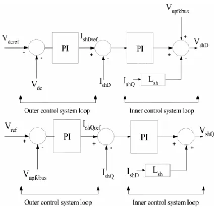
Fig. 2.De-coupled D-Q axis shunt converter control system.
C. Shunt Converter Control System
Fig.2 shows the de-coupled control system for the shunt converter. The D-axis control system controls the dc link capacitorvoltage and the Q-axis control system controls the UPFCbus voltage /shunt reactive power.The coupled control system has been de-signed based onlinear control system techniques and it consists of an outerloop control system that sets the reference for the innercontrol system loop. The inner control system loop tracksthe reference.
D. Series Converter Control Parameters
1) Transmission line real power flow controller parameters
Kp=1 ; Ki=4;
E. Series Converter Control System
Fig.3 shows the overall series converter control system. Thetransmission line real power flow(𝑃𝑙𝑖𝑛𝑒)
is controlled by injecting a component of the series voltage in quadrature with theUPFC bus voltage(𝑉𝑠𝑒𝑄).The transmission line reactive
power𝑄𝑙𝑖𝑛𝑒)is controlled by modulating the
International Journal of Research
Available at https://edupediapublications.org/journalse-ISSN: 2348-6848 p-ISSN: 2348-795X Volume 04 Issue 13
October 2017
Available online:
https://edupediapublications.org/journals/index.php/IJR/
P a g e | 102reference𝑉𝑙𝑖𝑛𝑒𝑟𝑒𝑓).The transmission line side
busvoltage is controlled by injecting a component of the seriesvoltage in-phase with the UPFC bus voltage . The parameters of the PI controllersTransmission line reactive power flow controller parameters:
a) Outer loop controller Kp= -0.1; Ki= -1;
b) Inner loop controller Kp= 0.15; Ki= 25;
Fig. 3. Series converter real and reactive power flow control system.
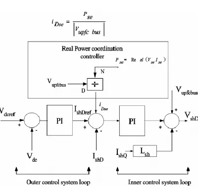
F. Real Power Coordination Controller
To understand the design of a real power coordination controller for a UPFC, consider a UPFC connected to atransmission line as shown in Fig.4. The interaction between the series injected voltage and thetransmission line current leads to exchange of realpower between the series converter and thetransmission line.
Fig.4. UPFC connected to a transmission line.
Available online:
https://edupediapublications.org/journals/index.php/IJR/
P a g e | 103Fig. 5. D-axis shunt converter control system with real power coordinationcontroller
III. SIMULATION RESULTS
An experimental UPFC system has been built to test the power control in transmission line. Recentadvances in high-voltage IGBT technology allow for higher switching frequency with lower loss, and thisallows for practical implementation of PWM control for high-power converters. So in the experiment, both theshunt converter and the series converter have been built as a three-phase PWM converter with IGBT as thepower device. The UPFC device is inserted into a transmission line, and with the help of the UPFC, the powerflow in the transmission line can be controlled effectively while maintaining the UPFC bus voltage constant.The parameters of the whole systems are given below:
Fig.6 Transmission line without UPFC
Fig.7 overall measurements of Transmission line without UPFC
International Journal of Research
Available at https://edupediapublications.org/journalse-ISSN: 2348-6848 p-ISSN: 2348-795X Volume 04 Issue 13
October 2017
Available online:
https://edupediapublications.org/journals/index.php/IJR/
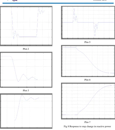
P a g e | 104Plot-2
Plot-3
Plot-4
Plot-5
Plot-6
Plot-7
Available online:
https://edupediapublications.org/journals/index.php/IJR/
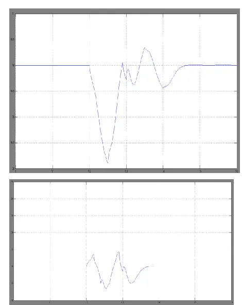
P a g e | 105Fig. 9. Impact of real power coordination controller
Fig. 10.Response of the power system to three-phase fault without UPFC.
Fig 11 Response of the power system to three-phase fault with UPFC.
IV. CONCLUSION
This paper has presented a new real and reactive energy coordination controller for a UPFC. The simple manipulate strategyis such that the shunt converter of the UPFC controls theUPFC bus voltage/shunt reactive strength and the dc linkcapacitor voltage. The series converter controls thetransmission line actual and re-lively energy waft. important coordination troubles were addressedin this paper associated with UPFC manage. One, the problem ofreal power coordination among the collection and the shuntconverter manage gadget. 2d, the problem of excessiveUPFC bus voltage tours for the duration of reactive powertransfers requiring re-active power coordination.
REFERENCES
International Journal of Research
Available at https://edupediapublications.org/journalse-ISSN: 2348-6848 p-ISSN: 2348-795X Volume 04 Issue 13
October 2017
Available online:
https://edupediapublications.org/journals/index.php/IJR/
P a g e | 106unifiedpower flow controller: A newapproachtopowertransmission control,” IEEE Trans. Power Delivery, vol.10, pp.1085–1097, Apr. 1995.
[2] C. D. Schauder, L. Gyugyi, M. R. Lund, D. M. Hamai,T. R. Rietman, D. R. Torgerson, and A. Edris,“Operation of the unified power flow controller (UPFC)under practical constraints,” IEEE Trans. PowerDelivery, vol. 13, pp. 630–636, Apr. 1998. [3] K. K. Sen and E. J. Stacey, “UPFC-UnifiedPowerflowcontroller: Theory, modeling, and applications,” IEEETrans. Power Delivery, vol. 13, pp. 1453–1460, Oct.1999.
[4] B. A. Renz, A. S. Mehraben, C. Schauder, E. Stacey, L.Kovalsky, L. Gyugyi, and A. Edris, “AEP unified powerflow controller performance,” IEEE Trans. PowerDelivery, vol. 14, pp. 1374–1381, Oct. 1999.
[5] P. K. Dash, S. Mishra, and G. Panda, “A radial basisfunction neural netwrok controller for UPFC,” IEEETrans. Power Syst., vol. 15, pp. 1293–1299, Nov. 2000.
[6] “Damping multimodal power system oscillation using ahybrid fuzzy controller for series connected FACTSdevices,” IEEE Trans. Power Syst, vol. 15, pp. 1360–1366, Nov. 2000.
[7] Z. Huang, Y. Ni, F. F. Wu, S. Chen, and B. Zhang,“Appication of unified power flow controller ininterconnected power systems-modeling, interface,control strategy and case study,” IEEE Trans. PowerSyst, vol. 15, pp. 817–824, May 2000.
[8] Y. Morioka, Y. Mishima, and Y. Nakachi,“Implementation of unified power flow controller andverification of transmission capability improvement,”IEEE Trans. Power Syst, vol. 14, pp. 575–581, May1999.
[9] P. C. Stefanov and A. M. Stankovic, “Modeling ofUPFC operation under unbalanced conditions withdynamic phasors,” IEEE Trans. Power Syst.,vol. 17, pp.395–1403, May 2002.
[10] H. F. Wang, “Aunified model for the analysis of factsdevices in damping power system oscillations part I:Single machine infinite-bus power systems,” IEEETrans. Power Delivery, vol. 12, pp. 941–946, Apr.1997.
[11] “A unified model for the analysis of facts devices indamping power system oscillations part II: Multimachine power syetms,”IEEE Trans. Power Delivery,vol. 13, pp. 1355–1361, Oct. 1998.