Fast Antenna Far-Field Measurement for Sparse Sampling
Technology
Liang Zhang1, *, Fei Wang2, Tianting Wang2, Xinyuan Cao1, Mingsheng Chen1, and Xianliang Wu2
Abstract—A main defect of far-field (FF) measurement techniques is long measurement time, which often leads to the problem of inefficient use of measurement facilities that is a strong limiting factor in many measurements. To solve this problem, in this study, we propose a technique to accelerate the antenna measurement that is achieved by sparse test results in the FF measurement system. In the data processing part of the measurement, the concept of the quadrature analog-to-information conversion (QAIC), which make the approach both efficient and easy to implement in existing FF measurement facilities, is discussed. Simulations are provided to show this low-speed uniform sampling approach. The proposed strategy is then applied to measure the pattern of a standard rectangular horn antenna in an anechoic chamber. The experimental results demonstrate that our technique can reduce the measuring time by at least 34.4% while guaranteeing the measurement accuracy. These results demonstrate the potentials of the method.
1. INTRODUCTION
Antenna measurements have become increasingly elaborate and time-consuming because the number of required sampling points grows quadratically with frequency in large size antenna development. Far-field (FF) measurement requires a large amount of data; consequently, the reduction of measurement time is a pivotal factor [1, 2]. Different techniques to reduce the overall test time in antenna measurements have been proposed. One approach is based on source reconstruction method [3, 4], in which the number of near-field (NF) samples is reduced, using a bisection method-based adaptive sampling scheme.
In this paper, a means to accelerate the antenna characterization in the FF measurements is proposed. Enlightened by the recent advances in compressive sensing, the main idea is to utilize the sparsity of the received signal to obtain the observation data of the reflected signal at a low rate and then solve the optimization problem by detecting the received data in the computer.
During the past decade, the development of the compressed sensing has undergone major changes in many aspects of data acquisition and processing [5–7]. Based on the method, many acquisition random measurement techniques have emerged [8–11]. One approach is based on “quadrature analog-to-information conversion (QAIC)” [12]; this approach is characterized by flexible bandwidth and blind sub-Nyquist sampling means and has the ability to optimize the system’s energy consumption and sensitivity performance and uses frequency down conversion to limit the RF bandwidth. In many applications such as signal processing, information theory, and electrical engineering, the idea of using sparsity to achieve low sampling rates has been found significant [13–16].
Received 25 April 2018, Accepted 9 August 2018, Scheduled 27 August 2018
* Corresponding author: Liang Zhang ([email protected]).
In recent years, the application of the compressive sensing method in electromagnetics is relatively new, as described in [17]. Progress has been made in antenna measurement and diagnosis. In the case of NF measurements, [18] proposed an approach that exploits existing measurement capabilities and allows a radical under-sampling via insertion of a priori information by suitable use of advanced numerical modeling tools. Another technique was reported in [19] that employs a technique to accelerate the NF antenna measurement via sparseE-field sampling in the region where theE-field changes smoothly and dense sampling in the region where the field changes rapidly. In [20], with a priori knowledge of the failure-free array radiation pattern, it is possible to reformulate the diagnosis problem, e.g., only the faulty elements or the localized field differences must be retrieved. A similar introduction can be found in [21, 22]. One approach [23] is to reduce the measurements points, by exploiting the sparsity of the spherical wave spectrum of antennas.
In this work, we propose to improve the FF measurement efficiency by employing sparse sampling of the measurement. The QAIC technique was added to regulate the collection of test data at the signal acquisition and processing section of the measurement system structure. To verify our design, the FF pattern of the horn antenna was measured in an anechoic chamber. The method of the proposed measurement system was preset to rapidly turn the turret while sparsely sampling and reconstructing the data. Furthermore, the proposed structure was characterized in terms of test efficiency and accuracy. The system sets different sampling sparse ratios and compares the error and timeliness with traditional measurement results.
2. QUADRATURE ANALOG-TO-INFORMATION CONVERT
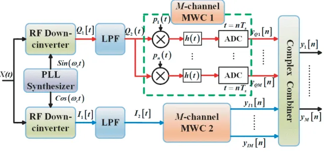
QAIC is a full-blind system that does not require knowledge of spectral information and spectral settings when sampling and recovering signals. By adding a pair of quadrature bases (Sin(ωct) and Cos(ωct)) at the front end of the modulated wideband converter (MWC) [24], the flexibility of the analog front-end bandwidth is increased; however, the complexity of the system is also increased. The block diagram of QAIC is shown in Fig. 1. The proposed QAIC system first multiplies the analog signal by a bank of periodic waveforms. The product is then low-pass filtered and sampled uniformly at a low rate.
Figure 1. Sparse sampling acquisition using the QAIC technique.
The set of model equations that describe the QAIC system discussed below is the key new subsystem block introduced, for which the QAIC is the downconverter impaired by image interference resulting in gain imbalance and phase imbalance in the frequency domain model. The frequency dependent Q, I mismatch and impairments are ignored in this work. pi(t) is a periodic PRBS, and its length is l= 2l0; therefore,
pi(t) =ej2πnfpt
∞
n=−∞
⎧ ⎪ ⎪ ⎪ ⎪ ⎪ ⎨ ⎪ ⎪ ⎪ ⎪ ⎪ ⎩ 1 L
L−1
k=0
αi,k n= 0
L−1
k=0
αi,kβnϕn,k n= 0
(1)
αi,k are the amplitudes of the branch PRBS;βn= (1−e−j(2π/l)n)/j2πnand ϕn,k =e(−j(2π/l)nk) refer to
Eq. (1). Theh(t) signal is lowpass filtered. The samplesIi[n] andQi[n] are aggregated, and the output of the complex combiner yi[n] is used to recover the support of the input signal X(t). The Fourier transform of the signals yi[n] is given as Eq. (2).
Yi= 1 Ts
l0
n=−l0
l
k=0
α
iϕn,kβn[XI(f−nfp) +XQ(f −nfp)] ∓jαiϕn,kβn[XI(f−nfp) +XQ(f−nfp)]
(2)
The system model of QAIC is given by Eq. (3), where ˜Φ is the sensing matrix, ˜Ψ the dictionary matrix, and ˜Θ the diagonal matrix.
Y =Az˜= ˜Φ ˜Ψ ˜Θ˜s(f) (3)
˜
Φ, ˜Ψ, and ˜Θ, described in Eq. (5) consist of matrices Φ ∈ Rm×l in Eq. (4). The rows of the matrix Φ contain the amplitudes of the m unique pseudorandom bit sequences in the QAIC. Ψ ∈ Cl×l is a discrete Fourier transform matrix, and Θ∈Cl×l is a diagonal matrix.
˜
Φ = Φ 0
0 Φ
, Ψ =˜ Ψ 0
0 Ψ
, Θ =˜ Θ 0
0 Θ
(4)
The vector ˜s(f)∈C2l is described in Eq. (5).
˜ s= ⎛ ⎜ ⎜ ⎜ ⎜ ⎜ ⎜ ⎜ ⎜ ⎜ ⎜ ⎜ ⎜ ⎜ ⎜ ⎝ 1
2[X(f−fc+l0fp) +X(f +fc+l0fp)] ..
. 1
2[X(f−fc−l0fp) +X(f +fc−l0fp)] 1
2j[X(f −fc+l0fp)−X(f +fc+l0fp)] ..
. 1
2j[X(f −fc−l0fp)−X(f +fc−l0fp)]
⎞ ⎟ ⎟ ⎟ ⎟ ⎟ ⎟ ⎟ ⎟ ⎟ ⎟ ⎟ ⎟ ⎟ ⎟ ⎠ (5)
We can easily recover the sparse vectors ˜s(f), thereby fixing the input signalX(t). It is efficient to use techniques from convex optimization if the matrix A in Eq. (3) reflects the geometry of the sparse vector ˜s(f).
(1−δ)s22 ≤ As22 ≤(1 +δ)s22 ∀2K0 — sparses (6)
In particular, if a small constantδsatisfies Eq. (6), then the sampling and reconstruction procedure will succeed.
Figure 2. Diagram of anechoic chamber measurement system with QAIC structure.
3. ANTENNA FAR-FIELD MEASUREMENT SYSTEM
The traditional antenna measurement system is shown in Fig. 2. The source antenna (SA) and the antenna under test (AUT) are connected to the transmit port and input port of the source and the microwave receiver, respectively. The test is controlled by the host computer. One of the main shortcomings of FF measurement methods is the large amount of data required, and consequently, a substantial amount of measurement time is required to collect these data. If the number of acquisitions can be reduced while retaining more useful information, then the measurement time can be decreased. By analyzing the operating mode of the system, it is possible to artificially control the signals collected between the microwave receiver and computer, and reduce the number of sampling points. The QAIC system model has two types of schemes: one involves processing before the receiver via direct sparse sampling; the other involves output signal processing after the receiver reduce to output.
This paper chooses the latter scheme to combine the uniform sparse sampling measurement technique with the anechoic chamber measurement system technology. The computer control signal generator sends a signal through the transmitting antenna. The microwave receiver receives the signal through the antenna under test, and the received signal acquires the observation data through the QAIC structure. A “pseudo-random modem” and “low-speed sampler (ADC)” are used to form a set of converters that can sample low-speed analog information and ensure that the sampled signal is not lost.
The above-described method involves the design of data processing software for the anechoic chamber measurement system based on QAIC structure in a computer based on the original measurement system. In the experiment, the sparse ratio of the signal acquisition is adjusted (the actual conversion is to control the turntable controller to send the acquisition command), the number of sampling points controlled, the corresponding observation data value generated, and the sparse data restored by the convex optimization calculation method. In this experiment, the commonly used OMP algorithm is used to recover the observed data.
4. EXPERIMENTAL ANALYSIS AND SIMULATION
Figure 3. Rectangular horn antenna far-field pattern measurement results.
(a) (b)
(c)
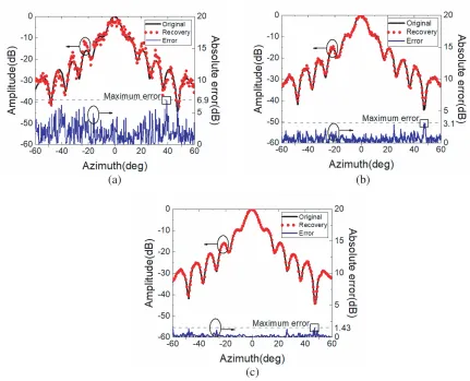
Figure 4. The reconstruction results of the far-field pattern for different sparse ratio sampling cases: (a) sample sparse ratio of 10%; (b) sample sparse ratio of 30%; (c) sample sparse ratio of 50%.
The FF pattern was measured using a horn antenna in the actual test. The entire measurement time was 360 seconds. The traditional antenna measurement required 1800 points (in a 360◦ range), and the measurement time was longer. The system reduces the sampling points and restores the measurement data. The data of the antenna azimuth plane pattern (in the range of−60◦ ∼60◦) are measured in this paper. The measurement results of far-field pattern are shown in Fig. 3.
The system and reconstruction of the FF pattern for different sampling numbers (sparse ratios) are analyzed, as shown in Fig. 4. The number of high-speed ADC samples N = 600 points was reconstructed with sparse ratios of 10%, 30%, and 50%, i.e., the sampling test points were 60, 180, and 300, respectively. The sampling sparse ratio is taken as 10%, and the reconstructed and recovered data are in the zero point of the pattern and the position of the side lobes in Fig. 4(a). The error is large, and the specific data information cannot be clearly determined. The maximum relative error is 6.9 dB at 39◦ azimuth. The sampling sparse ratio is taken as 30% in Fig. 4(b). The reconstructed data are in good agreement with the standard measurement data. The maximum relative error is at 47◦ azimuth, and the error value is reduced to 3.1 dB. The sampling sparse ratio is taken as 50% in Fig. 4(c). The reconstructed data are basically the same as the standard measurement data. The maximum relative error is at two zero positions of−60◦ and 47◦ at the azimuth, and the error value is reduced to 1.31 dB, which satisfies error requirements for the antenna measurement.
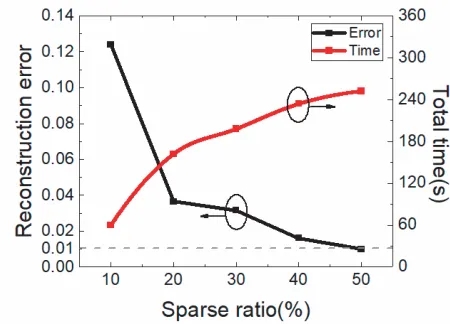
Experiments based on different sampling sparse ratios, new structure reconstruction measurement errors and time-consuming are analyzed in Fig. 5. The sampling sparse ratios were taken as 10%, 20%, 30%, 40%, and 50%. The reconstruction error is less than 0.01 when the sparse ratio is 50%, which satisfies the implied test error requirement. The total time of the entire system measurement and signal reconstruction recovery is proportional to the sampling compression ratio. The total measurement time is 236 seconds, when the system sampling sparse ratio is 50%. The measurement time of the proposed system is less than that of the traditional measurement of 360 seconds, and the test efficiency of the proposed system is increased by 34.4% compared to the traditional measurement.
Figure 5. Measurement error and time for different sparse ratio sampling cases.
5. CONCLUSION
ACKNOWLEDGMENT
This research was partially supported by Major Project of Provincial Natural Science Research of University of Anhui Province of China (Grant No. KJ2018ZD046 and No. KJ2018A0488), and the National Natural Science Foundation of China (Grant No. 61701163 and No. 51477039).
REFERENCES
1. Foged, L., O. Breinbjerg, S. Pivnenko, G. Di Massa, and C. Sabatier, “Antenna measurement facility comparison within the European antenna centre of excellence,” 2005 European IEEE Microwave Conference, Vol. 2, 4–792, 2005.
2. Nie, J., X. Li, G. Lou, and B. Gong, “Research of the objects characteristics and radiometric equation with sub-millimeter wave radiometer,” Journal of Microwaves, Vol. 26, No. 5, 82–86, 2010.
3. Li, P. and L. J. Jiang, “An iterative source reconstruction method exploiting phaseless electric field data,” Progress In Electromagnetics Research, Vol. 134, 419–435, 2013.
4. Li, P., Y. Li, L. J. Jiang, and J. Hu, “A wide-band equivalent source reconstruction method exploiting the Stoer-Bulirsch algorithm with the adaptive frequency sampling,”IEEE Transactions on Antennas and Propagation, Vol. 61, No. 10, 5338–5343, Oct. 2013.
5. Donoho, D. L., “Compressed sensing,” IEEE Transactions on Information Theory, Vol. 52, No. 4, 1289–1306, Apr. 2006.
6. Baraniuk, R. G., “Compressive sensing [lecture notes],”IEEE Signal Processing Magazine, Vol. 24, No. 4, 118–121, 2007.
7. Candes, E. J. and M. B. Wakin, “An introduction to compressive sampling,”IEEE Signal Processing Magazine, Vol. 25, No. 2, 21–30, Mar. 2008.
8. Kirolos, S., et al., “Analog-to-information conversion via random demodulation,” 2006 IEEE Dallas/CAS Workshop on Design, Applications, Integration and Software, 71–74, IEEE, 2006. 9. Slavinsky, J. P., J. N. Laska, M. A. Davenport, and R. G. Baraniuk, “The compressive multiplexer
for multi-channel compressive sensing,” 2011 IEEE International Conference on IEEE Acoustics, Speech and Signal Processing (ICASSP), 3980–3983, 2011.
10. Zhao, Y. J., Y. H. Hu, and J. J. Liu, “Random triggering-based sub-nyquist sampling system for sparse multiband signal,”IEEE Transactions on Instrumentation and Measurement, Vol. 66, No. 7, 1789–1797, Jul. 2017.
11. Rani, M., S. B. Dhok, and R. B. Deshmukh, “A systematic review of compressive sensing: Concepts, implementations and applications,” IEEE Access, Vol. 6, 4875–4894, 2018.
12. Haque, T., R. T. Yazicigil, K. J. L. Pan, J. Wright, and P. R. Kinget, “Theory and design of a quadrature analog-to-information converter for energy-efficient wideband spectrum sensing,”IEEE Transactions on Circuits and Systems I — Regular Papers, Vol. 62, No. 2, 527–535, Feb. 2015. 13. Duarte, M. F., et al., “Single-pixel imaging via compressive sampling,” IEEE Signal Processing
Magazine, Vol. 25, No. 2, 83–91, Mar. 2008.
14. Lustig, M., D. L. Donoho, J. M. Santos, and J. M. Pauly, “Compressed sensing MRI,”IEEE Signal Processing Magazine, Vol. 25, No. 2, 72–82, Mar. 2008.
15. Wang, M., W. Yu, and R. Wang, “Azimuth multichannel SAR imaging based on compressed sensing,”Progress In Electromagnetics Research, Vol. 141, 497–516, 2013.
16. Lin, X.-H., G.-Y. Xue, and P. Liu, “Novel data acquisition method for interference suppression in dual-channel SAR,”Progress In Electromagnetics Research, Vol. 144, 79–92, 2014.
17. Massa, A., P. Rocca, and G. Oliveri, “Compressive sensing in electromagnetics — A review,”IEEE Antennas and Propagation Magazine, Vol. 57, No. 1, 224–238, Feb. 2015.
19. Chiu, P. J., W. C. Cheng, D. C. Tsai, and Z. M. Tsai, “Robust and fast near-field antenna measurement technique,” International Journal of Microwave and Wireless Technologies, Vol. 8, No. 4–5, 777–784, Jun. 2016.
20. Fuchs, B., L. Le Coq, and M. D. Migliore, “Fast antenna array diagnosis from a small number of far-field measurements,”IEEE Transactions on Antennas and Propagation, Vol. 64, No. 6, 2227–2235, Jun. 2016.
21. Migliore, M. D., “A simple introduction to compressed sensing/sparse recovery with applications in antenna measurements,” IEEE Antennas and Propagation Magazine, Vol. 56, No. 2, 14–26, Apr. 2014.
22. Morabito, A. F., R. Palmeri, and T. Isernia, “A compressive-sensing-inspired procedure for array antenna diagnostics by a small number of phaseless measurements,” IEEE Transactions on Antennas and Propagation, Vol. 64, No. 7, 3260–3265, Jul. 2016.
23. Fuchs, B., L. Le Coq, S. Rondineau, and M. D. Migliore, “Fast antenna far-field characterization via sparse spherical harmonic expansion,” IEEE Transactions on Antennas and Propagation, Vol. 65, No. 10, 5503–5510, Oct. 2017.