1
Temperature Control of Stirred Tank Heater using Optimal
Control Technique
Mustefa Jibril1, Messay Tadese2, Eliyas Alemayehu Tadese3
1 Msc, School of Electrical & Computer Engineering, Dire Dawa Institute of Technology, Dire Dawa, Ethiopia
2 Msc, School of Electrical & Computer Engineering, Dire Dawa Institute of Technology, Dire Dawa, Ethiopia
3 Msc, Faculty of Electrical & Computer Engineering, Jimma Institute of Technology, Jimma, Ethiopia
Abstract
This paper presents the application of optimal control problem in modeling of stirred tank heater temperature control. The analysis of the open loop system shows that the system is not efficient without a controller. Linear Quadratic Gaussian (LQG) and Linear Quadratic Integral (LQI) controllers are used to increase the performance of the system. Comparison of the closed loop system with the proposed controllers have been done with Matlab/Simulink Toolbox and a promising results have been analyzed.
Keywords: Stirred tank heater, Linear Quadratic Gaussian, Linear Quadratic Integral
1. Introduction
Mixing Vessels play an essential function in chemical processes. Its utilities are varied and range from blending chemicals to converting temperatures of fluids. In the look at of stirred tank heaters, we are able to use it typically as an instrument for varying the temperature of fluid present in the tank. We normally use a steam enters and leave the tank through a pipe. Here, we use the steam to increase the temperature of the tank. The objective is to control the output temperature of the tank at desired value for the operating condition.
2. Mathematical Modeling of the Stirred Tank Heater
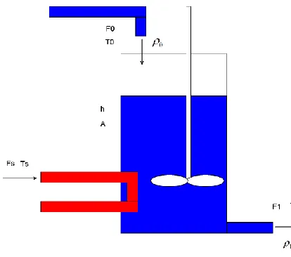
The stirred tank heater system is shown in Figure 1 below.
2
Figure 1 Stirred tank heater
The material balance on this system will be:
0 0 1 1 0 0 1 1 1
d h dm
F F A F F
dt dt
Assuming constant cross-sectional area, A. The energy balance is:
0 0 ˆ0 1 1 ˆ1 0 0 ˆ0 1 1 ˆ 2dE
F H F H Q F H F H Q
dt
Remember, within the tank:
3
d U K P
dE dU dH
dt dx dt dt
So
0 0 0 1 1
ˆ
ˆ ˆ 4
d VH dH
F H F H Q
dt dt
If we assume that the enthalpy can be expressed as:
ˆ
ˆ ˆ 5
p ref ref
HC TT H
Then with
0
ˆ 0
ref ref T
H
3
0 0 0 1 1
ˆ
ˆ ˆ 6
p
p p
d VC T
F C T F C T Q dt
Rearranging Equation (6) becomes
0 0 0 1 1 ˆ 7 p
d VT Q
F T F T
dt C
If we assume, then: =constant and
0 1
dh
V A F F
dt
Then Equation (7) becomes
0 0 1 ˆ 8
p
d hT Q
A F T F T
dt C
Rearranging Equation (8) becomes
0 0 1 ˆ 9
p
dh dT Q
TA hA F T FT
dt dt C
Inserting the material balance:
0 1
0 0 1 ˆ
10p
dT Q
T F F hA F T FT
dt C
Rearranging Equation (10) becomes
0 0 ˆ
p
dT Q
hA F T T
dt C
Where
H h t
If we make the assumption that dh 0
dt then V hA constant and F0 F1 so
0 0 ˆ 11
p
dT Q
V F T T
dt C
4
s
QUA T T
Then Equation (11) becomes
0 0 ˆ 12
s p
UA T T dT
V F T T
dt C
Then arranging Equation (12) yields
0 1 13 s f dTaT T KT
dt
Where
0
1 1
,
ˆ
f p f
F UA
K and a K
V VC
Letting x1 T x, 1 dT,u1 T and u0 2 Ts dt
yields to the state space form
0 1 14 s f TT aT K
T y T For
0.2sec, 0.4 5.4
f K and a
The state space representation becomes
0
5.4 5 0.4 15
s T T T T y T
3. Proposed Controllers Design 3.1 LQG optimal controller Design
LQG computes an optimal controller to stabilize the plant G(s)
16x Ax Bu y Cx Du
5
0 17lim
T C T T LQG T T CQ N x
J E x u dt
u N R
The block diagram of a stirred tank heater system with LQG controller is shown in Figure 2 below
Figure 2: Block diagram of a stirred tank heater system with LQG controller
The solution of the LQG problem is a combination of the solutions of Kalman filtering and full state feedback problems based on the so-called separation principle.
The plant noise and measurement noise are white and Gaussian with joint correlation function
18f T T f N t
E t t
N
The input variables W and V are
; f C T T C f N Q N W V
N R N
The final negative-feedback controller becomes:
2 2 22:
0
f C f C f
C
A K C B K K D K K F s K
For the Gaussian noises
and:1
0
0
5
0
0
1
0
0
5
0
0
1
and
6
1 0 0.1
0 1
Q and R
The LQG controller becomes
11 1
2
1
5.72 0.09181
0.04534
0.003627
u
L L
u
y L
3.2 Linear Quadratic Integral Controller Design
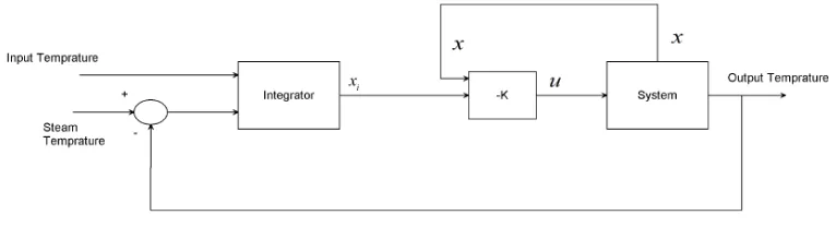
LQI computes an optimal state-feedback control law for the tracking loop. Block diagram of a stirred tank heater system with LQI controller is shown in Figure 3 below.
Figure 3Block diagram of a stirred tank heater system with LQI controller
For a plant sys with the state-space equations
19x Ax Bu y Cx Du
The state-feedback control is of the form
, i
20u K x x
Where xi is the integrator output. This control law ensures that the output y tracks the reference
command r. For MIMO systems, the number of integrators equals the dimension of the output y. LQI calculates the optimal gain matrix K, given a state-space model SYS for the plant and weighting matrices Q, R, N.
7
1 0
1 ; 1 0
0 1
Q R and N
The LQI optimal gain matrix becomes
1 0
K
4. Result and Discussion
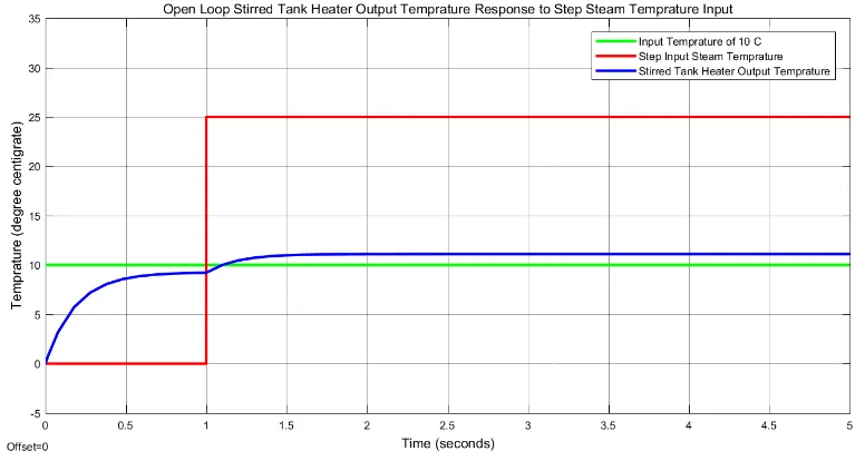
4.1 Open Loop Response of the Stirred Tank Heater
The open loop response of the stirred tank heater system for a 10 0
C input temperature and a step (from 0 to 25 0
C) steam temperature simulation result is shown in Figure 4 below.
Figure 4 Open loop response
The result shows that the output temperature is 11 0
C for a steam temperature of 25 0
C. This system is not efficient because to produce an 11 0C the system uses excess steam temperature.
4.2 Comparison of the Closed Loop Response of the Stirred Tank Heater with LQG and LQI Controllers for a Step Steam Temperature Input
8
Figure 5 Closed loop response of the stirred tank heater with LQG and LQI controllers for a step steam temperature
The simulation result shows that both the proposed controllers improved the output temperature but the stirred tank heater with LQG controller performance is better because the system improves the settling time and the percentage overshoot.
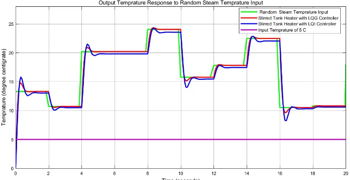
4.3 Comparison of the Closed Loop Response of the Stirred Tank Heater with LQG and LQI Controllers for a Random Steam Temperature Input
Comparison of the closed loop response of the stirred tank heater with LQG and LQI controllers for a 5 0
C input temperature and a random (between 10 to 25 0
C) steam temperature simulation result is shown in Figure 6 below.
9
The simulation result shows that the stirred tank heater with LQG controller performance is better than the stirred tank heater with LQI controller in improving the output temperature, settling time and the percentage overshoot.
5. Conclusion
In this paper, the modeling and design of stirred tank heater temperature control have been done successfully. The analysis and simulation of the open loop stirred tank heater proved that the system is not efficient and to improve the output temperature a feedback controller is needed. In this paper, an optimal control method is used to improve the system. Linear Quadratic Gaussian and Linear Quadratic Integral controllers are used. Comparison of the closed loop response of the stirred tank heater with LQG and LQI controllers have been done for a step and random steam temperature input signal. For the step input signal the simulation result proved that both the proposed controllers improved the output temperature but the stirred tank heater with LQG controller performance is better because the system improves the settling time and the percentage overshoot while for the random input signal the simulation result proved that the stirred tank heater with LQG controller performance is better than the stirred tank heater with LQI controller in improving the output temperature, settling time and the percentage overshoot. Finally, the comparative simulation results proved that the stirred tank heater with LQG controller performance is better than the stirred tank heater with LQI controller.
Reference
[1]. Yongjun Z. et al. “An Investigation of the Heat Transfer Performance of Dual Improved Intermig Impellers in a Stirred Tank with an Inner Heating Coil” Brazilian Journal of Chemical Engineering, Vol. 36, No. 3, 2019.
[2]. Normah A. et al. “Modeling of Two Continuous Stirred Tank Heat Exchangers in Series using Neural Network” International Journal of Engineering and Technology, Vol. 8, No. 12, pp. 250-255, 2019.
[3]. A.V. Divya et al. “Real Time Implementation of Fuzzy Based PID Controller Tuning for Continuous Stirred Tank Heater (CSTH) Process” Journal of Fuzzy Systems, Vol. 10, No. 3, 2018.
[4]. Prada et al. “Numerical Prediction of a Nussle Number Equation for Stirred Tanks with Helical Coils” AICHE Journal, Vol. 63, pp. 3912-3924, 2017.
[5]. Nurul Ikhlas S. et al. “Optimization of PID Control Parameters with Genetic Algorithm Plus Fuzzy Logic in Stirred Tank Heater Temperature Control Process” International Conference on Electrical Engineering and Computer Science (ICECOS), 2017.
[6]. Normah A. et al. “Design and Simulation of Hierarchical Control of Two Continuous Stirred Tank Heater in Series” Indian Journal of Science and Technology, Vol. 9, Issue 21, pp. 1-12, 2016.