DOI : https://doi.org/10.32628/CSEIT1953149
Visible Light Communication for Data and Audio Transmission using Light
-Fidility (Li-Fi)
Z. Asmathunnisa*, S. Manavalan, N. Kumar
Department of Computer Science and Engineering, St.Anne’s College of Engineering and Technology, Panruti
India ABSTRACT
LiFi is a wireless optical networking technology that uses light-emitting diodes (LEDs) for data transmission. LiFi is designed to use LED light bulbs similar to those currently in use in many energy-conscious homes and offices. LiFi data is transmitted by the LED bulbs and received by photoreceptors. Li-Fi technology transmits data at very high speed and is capable of delivering 224GB of data per second. Furthermore, it offers better security as compared to Wi-Fi. Due to its high speed, Li-Fi technology can be widely used in electromagnetic sensitive areas, such as, hospitals, airplanes, and nuclear power plants. Light Fidelity (Li-Fi) is a data transfer technique that uses light. Light is analogous not only to illumination but also to speed. Li-Fi is also much secured since light cannot pass through walls. It uses visible light portion of the electromagnetic spectrum to transmit information. Hence the visible light communication solves the problem of radio frequency congestion. In this project we transmit data and audio through light at very high data rates without use of microcontrollers and its other peripheral devices.
Keywords : Visible light, Secured, High Speed
I. INTRODUCTION
Light Fidelity (Li-Fi) is a
bidirectional,
high-speed and fully networkedwireless
communication
technology similar toWi-Fi
. Li-Fi is the term some have used to label the fast and cheap wireless communication system, which is the optical version of Wi- Fi. Li-Fi uses visible light instead of Gigahertz radio waves for data transfer.The term was coined by
Harald Haas
and is a form ofvisible light
communication
and a subset of optical wireless Communications (OWC) and could be a complement toRF communication
(Wi-Fi orcellular networks
), or even a replacement in contexts ofdata broadcasting
. The light waves cannot penetrate walls which makes a much shorterrange, though more secure from hacking, relative to Wi- Fi.
wavelengths is called visible light. A typical human eye will respond to wavelengths from about 390 to 700 nm. The dramatic growth in the use of LEDs (Light Emitting Diodes) for lighting provides the opportunity to incorporate Li- Fi technology into a plethora of LED environments. Li-Fi is particularly
suitable for many popular internet “content consumption” applications such as video and audio downloads, live streaming, etc. These applications place heavy demands on the downlink bandwidth, but require minimal uplink capacity. In this way, the majority of the internet traffic is off-loaded from existing RF channels, thus also extending cellular and Wi-Fi capacities.
Although Li-Fi LEDs would have to be kept on to transmit data, they could be dimmed to below human visibility while still emitting enough light to carry data. It offers much larger frequency band (300 THz) compared to that available in RF communications (300GHz). Researchers reached bit rate of 224 GB/s which is 100s of times faster than our average WI-FI connection at home or office. Also, more data coming through the visible spectrum could help alleviate concerns that the electromagnetic waves that come with Wi-Fi could adversely affect our health. Li-Fi can be the technology for the future where data for laptops, smart phones, and tablets will be transmitted through the light in a room.
II. EXISTING DATA & AUDIO COMMUNICATION USING LI-FI
A. DATA TRANSMISSION AND RECEPTION Optical wireless technologies called visible light communication (VLC) are more recently referred to as LiFi, offers an entirely new paradigm in wireless technologies in terms of communication speed, flexibility and usability. LEDs (Light Emitting Diodes) are recognized in the terms of green lighting resource because they contain no hazardous materials such as mercury emitted by
fluorescent lamps LED’s have a unique ability that
goes beyond their use as energy-efficient lighting devices. They can be switched on and off within nanoseconds, which makes them super-fast transmitters of binary data. This flickering occurs
faster than the eye can see, so even LED’s used for
room lighting can be used to transmit data.
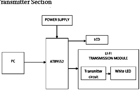
Transmitter Section
Figure1. Transmitter block diagram using Atmel
Receiver Section
Figure 2. Receiver block diagram using Atmel
This ON-OFF modulation of the LED light transmits the data. The receive section consists of a photodiode, e.g. silicon photo detector or an Infrared germanium cylindrical detector. The photo detector demodulates the incoming received signal based on the sequence of 1s and 0s. The demodulated signal is then sent to a filter to remove unwanted noise. This filtered signal is then amplified using signal amplification mechanism. The filtered and amplified signal is then given to an output device such a speaker
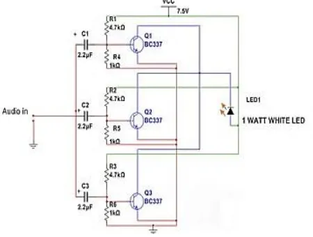
B.AUDIO TRANSMISSION AND RECEPTION The circuit consists of two parts, which are receiver and transmitter. The transmitter consists of 3 transistors and few passive components paired with 1 watt LED. Which will changes its brightness with respect to audio signal. But changes in brightness due to audio signal will not visible to human eye. We only see static illumination of white LED. The receiver consists of a photo detector (here I used solar cell) which is paired with an amplifier. The sound output is given by the speaker. The transmitter is transistorized amplifier which consists of 3 amplifiers connected in parallel to drive the 1 watt white LED. Each transistor base consists of voltage divider which gives necessary bias for the individual transistor. The input stage
has capacitors at each transistor’s base for blocking
DC signals which could degrade the quality of output.
Figure 3. Audio Transmitter Circuit
The receiver consists of a 6 volt solar cell (3 volts above works fine) in series with 2.2uf capacitor which is paired with an amplifier. The amplifier need not to be the same illustrated here, but you can use any amplifier lying around your house. But make sure it as good sensitivity.
III. PROPOSED METHOD
A. DATA TRANSMISSION AND RECEPTION
The main advantage is visible light’s frequency
spectrum bandwidth, which ranges from 430 THz to 750 THz. The bandwidth is much larger than the radio frequency bandwidth, which ranges from 3 kHz to 300 GHz. A new generation of high brightness light-emitting diodes forms the core part of light fidelity technology.
Figure 4. Block diagram of proposed data transfer system
The input data is given as a input to the X-CTU software.
lower speed, typically at standard rates such as 2400, 4800, 9600, 19200 baud etc.
Here the input data’s (character/numbers)
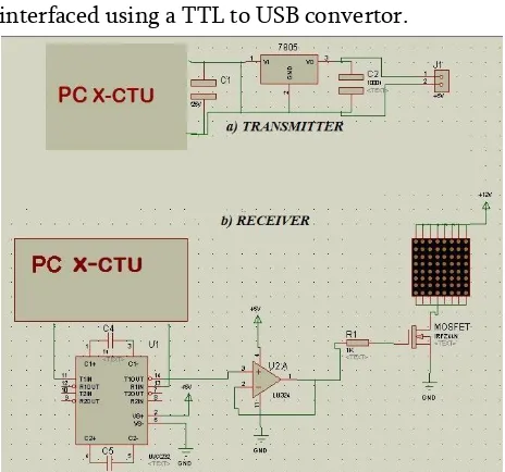
corresponding ASCII value is generated and simultaneously converted to BINARY and given to the LED .The laptop and the circuit is interfaced using a TTL to USB convertor.
Figure 5. Circuit diagram of proposed data transfer system
The receiving terminal also comprises of similar hardware except for the photo detector to track the data sent through the light from the led system. It consists of the phototransistor as a light sensor, whose output is fed to a comparator built using low power OP-AMP The comparator circuit makes the DATA IN into binary compatible levels. Even though the amount of light falling on the phototransistor varies, the comparator ensures that it is modified to a correct binary level. The corresponding flickering to the BINARY 1s & 0s is performed continuously to form a data in the form of an array. This is done to obtain data rates in the range of hundreds of megabits per second. The LED intensity is modulated so rapidly that human eye cannot notice, so the light of the LED appears constant to humans.
The receiving section is interfaced with another laptop where the received data (from the transmitter) is seen in the X-CTU software, where the BINARY value that is converted to ASCII values and the output is displayed in the XCTU terminal of the laptop.
B. AUDIO TRANSMISSION AND RECEPTION The analog input is given through the AUX cable. Here analog input in form of music, which is connected with the biasing circuit consisting of BC337 transistors paired with passive components and connected to the 1W LED .The transmitted signal from the LEDs has to be detected and acknowledged. So in order to detect the message signal from the blinking led light we use a solar cell which comprises large number of photocells connected in series.
Figure 6. Block Diagram of proposed audio transfer system
The solar cell detects the variation in light, since the blinking can be easily detected and output of the solar cell will be in analog form. So using solar cell we could detect and demodulate the message signal transmitted. The demodulated signal will be at low voltage range.
IV.RESULTS AND DISCUSSION
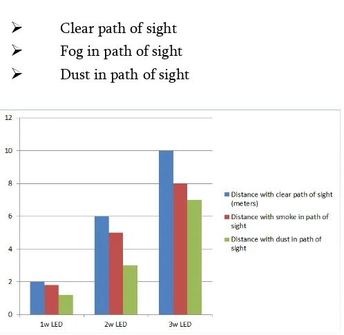
fog, Smog, dust, etc.. We have tested with 3 different cases as with
➢
Clear path of sight➢
Fog in path of sight➢
Dust in path of sightFigure 7. Comparison of different LEDs and distance travelled by light ray under different
conditions
We have found that the distance reached by the light ray with clear path of sight is maximum when compared with the distance reached with fog and dust in the path of sight.
The input voltage consumed by the existing and the proposed model is shown below:
Figure 8. Comparison between voltage consumed by proposed model and Atmel
Here the input is a constant 5V. But the output voltage fed to the LED in our project is the same 5V whereas in Atmel the voltage fed to LED is only 4V and 1V is consumed by the circuit.
AUDIO TRANSMISSION RECEPTION USING Li-Fi Similarly the waveforms are plotted for the input and output audio signals using MATLAB. The input analog signal from the transmitter circuit and the output signal received at the other end of the circuit is recorded and the waveforms are plotted accordingly.
Figure 9. Transmitted Audio
Figure 10. Received Audio
By comparing the above two waveforms, we have proved that the signal sent and received are almost same.
input voltage input
V. CONCLUSION
Li-Fi is the trend of today and near future. It is one of the cheapest and efficient mode of data transfer. These methods can be used to transfer data and audio in a better way. Based on the observations and the graphical results obtained from the proposed circuitry it is clear that the transfer of data and audio without the use of microcontrollers is much more efficient and powerful.
VI.REFERENCES
[1]. K. Lakshmisudha, Divya Nair, Aishwarya Nair,
Pragya Garg” Li-Fi (Light Fidelity)”,
International Journal of Computer Applications (0975 – 8887) Volume 146 – No.15, July 2016 [2]. Mr. Shailendra Yadav and, Mr. Pradeep Mishra
“LI-FI Technology for Data Transmission
through LED” in Imperial Journal of
Interdisciplinary Research (IJIR) Vol-2, Issue-6, 2016
[3]. Deepali Bajaj, Isha Mangal, Asha Yadav,
“Towards an understanding of Li-Fi: Next generation Visible Light Communication Technology, Volume 4 Issue 4 (April 2015) [4]. Anil jaykumar chinchawade, Prof. K.Sujatha
“light based Audio transmission with
home\office automation system” Vol. 5, Issue 7,
July 2016
[5]. S.Dimitrov and H.Haas, principle of LED light communication: toward networked Li-Fi. Cambridge University press, Mar 2015.
[6]. Nikhil Gujral, “LiFi(LED Based Data
Transfer),International journal on recent and innovation in computing and communication,vol:4 issue:3
[7]. Girish Radakrishnan, “How to make simple LiFi circuit”, Feb2015
[8]. Li-Fi (LED Based Data Transfer) N. Gujral , Sagar Dolas, in International Journal on Recent
and Innovation Trends in Computing and Comm. ISSN: 2321-8169 Volume: 4 Issue: 3 [9]. Liju Sajan1 , Lince Mathew2 , Abraham
Thomas3 , Sarun Sathyan4, Bibin Baby”
WIRELESS DATA TRANSFER USING VISIBLE
LIGHT COMMUNICATION” IJRET:
International Journal of Research in Engineering and Technology.
[10]. Harald Haas and C.Chen, ”What is Li-Fi” in
journal of light wave technology,July 2011 [11]. H.Haas, “wireless data from every light bulb,”
TED Website,Aug2011.
Cite this article as :