CSEIT1722276 | Received : 07 April 2017 | Accepted : 16 April 2017 | March-April-2017 [(2)2: 822-827]
International Journal of Scientific Research in Computer Science, Engineering and Information Technology © 2017 IJSRCSEIT | Volume 2 | Issue 2 | ISSN : 2456-3307
822
Walking Stick and ITS Important Features
Shallu Dhiman, Ramanpreet Kaur, C. K. Raina
Department of Computer Science and Engineering, Punjab, India
ABSTRACT
In modern era everyone wants to be independent. Independence is the building methodology in achieving goals and objectives in life. The persons who are physically challenged also want to be self-dependent. He never wants to depend on others .There are millions of visually impaired or blind people in this world who are always need of helping hands. From many years white cane are used for navigation for blind people and later this white cane has been improved by remote sensors which helps these visually challenged people in every walk of their life. Blind people have to face many problems while walking on streets and on stairs with the white cane. Another technology improvement is the invention of electronic stick which makes blind people life more convienient.The main motive of this paper is to spread knowledge to the blind people about these inventions of technologies.
Keywords: - Blind Stick, Microcontroller, And Infrared, Ultrasonic.
I.
INTRODUCTION
There are approximately millions of people across the globe who are blind. Even for the non-visually impaired the congestion of obstacles is sometimes problematic, it‟s even worse for the visually impaired. People with visual disabilities are often dependent on others such humans, trained dogs, or special electronic devices as support systems for decision making. Existing devices are able to detect and recognize objects that come on the floor, but a considerable risk is also includes the objects that are at a sudden depth, or stairs. Thus we were motivated
To develop a smart white cane to overcome these limitations. The most common tool that the blind Currently use to navigate is the standard white cane. We decided to modify and enhance the walking cane, since blind are only able to detect objects by touch or by cane. The user sweeps the cane back and forth in front of them. When the cane hits an object or falls off of the edge of a stair, the user then becomes aware of the obstacle –sometimes too late. We accomplished
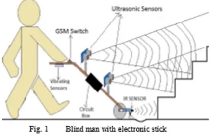
This goal by adding ultrasonic sensors at specific positions to the cane that provided information about the environment to the user through audio feedback. Smart white cane is specially designed to detect obstacles which may help the blind to navigate carefree. The vibration feedback and the audio messages will keep the user alert and considerably reduce accidents. The cane will warn whenever there are steps ahead and communicate whether they are going up or down accordingly. The intensity of vibrations is an indication of the closeness of an obstacle in the walking path of the user.
II.
REVIEW OF EXISTING DEVICES
Many ETS and robot technologies have been applied, to guide the blinds that aimed at improving their way of life in terms of safety, detect obstacles on ground, uneven surfaces, holes, stairs and puddles.
2.1 Laser Cane Walking Stick
It is specifically designed to help people with gait freezing or gait ignition failure such as occurs in Parkinson‟s disease and other Parkinson and conditions.
It is also useful for:
Abnormal gait patterns such as Ataxia Stroke rehabilitation which typically last at least six months
All wires and laser components are hidden and doors in conjunction with either a cane, a guide dog or residual vision. The use of the device must be taught by a correctly trained Mobility Instructor. Our experience has revealed that, provided the client has suitable primary mobility skills, the use of the Sonic Pathfinder may be learned in five or six training sessions spread over two or three days. The Sonic Pathfinder gives the user advanced warning of objects which lie within his or her travel path. In the absence of any such object the device switches to its lower priority function of providing information about the proximity of the shoreline. Increased safety is the main goal; however, this secondary role means that the device also provides some useful orientation information. Although designed for outdoor use, an accomplished user might well obtain some value using it in large public buildings. Use in a normal home setting is virtually impossible because of the presence of many close objects. The device will work in rain and snow; it will only fail when the transducers become saturated.
2.3 The NAVBELT - A Computerized Travel Aid for the Blind
In order for a blind person to follow a particular route, the person must have some concept or plan of that route. The traveller can learn the route while being guided by a sighted escort, or May only have verbal instructions to go by. The principle of the NavBelt is based on transferring an advanced obstacle avoidance system originally developed for mobile robots. The NavBelt consists of a belt, a small computer worn as a back pack, and equipped with ultrasonic sensors. The computer processes the signals arriving from the sensors, applies the obstacle avoidance algorithms, and relays them to the user via stereophonic headphones, using stereo imaging techniques.
III.
SYSTEM DESCRIPTION
The features are
Different types of vibrations for different obstacles. Automatic (during night time i.e. LDR dependent) high intensity (Red colour) LEDs.
A small Torch on the top.
A user controlled horn for traffic.
More efficient and inexpensive than other devices.
Easy to access for blinds.
Code can be upgrade or change easily.
3.1 Ultrasonic Sensor
Ultrasonic Sensor (transducers) is a type of sensor that uses sound waves to detect an object or target [10].It works on similar principle of radar or sonar which generates high frequency sound waves and evaluates the echo which is received back by the sensor [7]. Sensors calculate the time. Interval between sending the signal and receiving the echo to determine the distance to an object.
3.2. Infrared Sensor
An IR sensor is an electronic device that emits and/or detects infrared radiations in order to sense
some aspect of its surroundings [17]. When an object is close to the sensor, the light from the IR transmitter led bounces off the object and received by receiver led.
3.3. GSM
GSM stands for Global System for Mobile Communication and is an open, digital cellular technology used for transmitting mobile voice and data services. GSM module makes use of
Narrowband Time Division Multiple Access (TDMA) technique for transmitting signals.
3.4. ATmega328
ATmega328 is a microcontroller, can be also use in Arduino board which is an open-source physical computing platform based on Atmel microcontrollers, and a development environment for writing software for the board. It can be used to develop interactive objects, taking inputs from a variety of switches or sensors, and controlling other physical outputs.
IV.
FUNCTIONAL DESCRIPTION
A. Ultrasonic Sensor
wave moves at a velocity (the wave velocity) that is determined by the material properties and shape of the medium [15]. Laplace proposed that the speed of a longitudinal wave is given by
Where, from equation (1), P is the pressure, is density a d γ is dimensionless constant. At atmospheric pressure γ=1.4, P= 0.76×13600×9.8 Pa and =1.29, therefore, ν = 332 m/s, it means ultrasonic waves travel in air with speed of 332 m/s. The function of the transducers is to convert electrical energy into mechanical energy which directly corresponds to ultrasonic vibration [1].
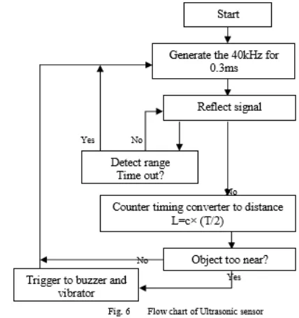
Fig. 5 shows the principles of measuring distance and is called the "pulse reflection method" which count the number of reference pulses [10]. This method is used to measure reflection time up to the object between transmitting pulse and receiving pulse of the ultrasonic wave. The relationship between the distance up to the object L and the reflecting time T can be expressed by L = c × T/2 Where, c is the velocity of wave.
The table shows the error % of gathered data of SR04, as shown in fig. 2, ultrasonic sensor which provides approximately 2cm-300cm non-contact measurement function with accuracy of 3mm. Fig.
6 shows the working flow chart of an ultrasonic sensor
B. Infrared Sensor
In an unknown environment, it is important to know about the nature of surface properties in order to interpret IR sensor output as a distance measurement. IR sensors using reflected light intensity to estimate the distance from an object. The function of the detector led (RX) is to detect the energy reflected by an obstacle from the emitter IR led (TX).The signal returned from the sensor is dependent on the energy emitted from the transmitter LED.
op-amp ≈ 3 and assuming R3 = 10kΩ, R2 = 4.7kΩ. Resistance R1=220kΩ must be larger than maximum resistance of detector led. R4 (~150Ω) is a voltage divider, calibrate according to intensity of emitter led [4]. When the intensity of emitter led is high, more energy will fall on detector led and resistance of detector is low, so the value of the potential (VIN) is high. Similarly when the intensity is low, the resistance of the detector is high and so the value of potential is low. This potential is compared with a reference potential. According to these compared potentials the output will be 1 or 0 i.e. „ON‟ or „OFF‟.
C. GSM
A GSM (Global System for Mobile communication) module is a specialized type of module which accepts a SIM (Subscriber Identity Module) card, and operates over a subscription to a mobile operator. When a GSM module is connected to a microcontroller (ATmega328), this allows the microcontroller to use the GSM module to communicate over the mobile network. A GSM module exposes an interface that allows applications to send and receive messages over the module interface. To perform these tasks, a GSM module must support an “extended AT command set” for sending/receiving SMS messages. The AT commands are sent by the microcontroller to the module. The module sends back an Information Response i.e. the information requested by the action initiated by the AT command. This is followed by a Result Code. The result code tells about the successful execution of that command. Text message may be sent through the module by interfacing only three signals of the serial interface of module with microcontroller i.e., TXD, RXD and GND. In this scheme RTS and CTS signals of serial port interface of GSM Modem are connectedwith each other.
AT+CMGF = 1, this command configures the GSM module in text mode. AT+CMGS = +917708377615, this command sends the mobile number of the recipient mobile to the GSM module. GSM configured with microcontroller using two modes- automatic and manual. If the object is too near and system is sending alert sounds and vibrations then automatically it send the message to the stored mobile number. Fig. 8 shows an algorithmic flow chart of GSM module for blind stick.
D. Microcontroller (ATmega328)
An ATmega328, has 14 digital input/ output pins (of which 6 can be used as PWM (Pulse Width Modulation) outputs), six analog inputs with one 16 MHz crystal oscillator. For Communication purposes it has a number of facilities for communicating with a computer, or with other microcontrollers. The ATmega328 provides UART TTL serial communication which is available on digital pins 0(RX) and 1(TX)
V.
LITERATURE SURVEY
water sensor. Even this is a PIC based system. The feedback given is through the vibration as well as the headphones. There is a GPS system where-in the user has to feed his location. No information on how a blind man would do that. Also they haven‟t mentioned anything about the size and shape of their cane and neither about the placement of their circuitry.
VI.
SALIENT FEATURES
6.1. Affordability - The estimated price for mass production should not exceed Rs.500. As majority of blind
6.2. Population in the developing countries are poor, this provides an economical solution. Versatility – Apart from the low level obstacles even the ones above waist and types of staircases can be determined.
6.3. Design – The bottom wheel – The blind generally tap while sweeping which is avoided by using a wheel.
6.4. The entire circuitry along with the battery compartment is concealed inside the stick reducing the risk of damage to the circuit and reducing bulkiness. Handle – ON/OFF switch, vibration feedback and the audio jack is provided on the handle itself.
6.5. Audio feedback – Short pre-recorded messages informing the user about the obstacles are played. The benchmark in aid for the blind like crutches is for the paraplegic.
VII.
CONCLUSION
As awalking stickis a device used to facilitatewalking, for fashion, or for defensive reasons but in the whole paper it works like a helping hand for visually impaired people who cannot see the things and need someone for their help. The walking stick works like a human being who is physically challenged. It affection so we have the duty as a human being that we should not show sympathy to these people like a poor I fact we should help them that they can be like a normal human being with the help of these new invited
technologies. I would conclude that for the dumb people there is an opportunity to live a happy life without depends on others for their day-to-day work.
VIII.
REFERENCES
[1]. Manoj Badoni and Sunil Semwal, "Discrete Distance And Water Pit Indicator Using Avr Atmega8 In Electronic Travel Aid For Blind”, International Journal of Disaster Recovery and Business Continuity Vol. 2, November, 2011. 2Sung Jae Kang, Young Ho, Kim, In Hyuk Moon, "Development Of An Intelligent Guide-Stick For The Blind”, IEEE International Conference on Robotics & Automation Seoul, Korea, May 21-26, 2001.
[2]. Alessio Carullo and Marco Parvis, "An Ultrasonic Sensor for Distance Measurement in Automotive Applications”, IEEE Sensors Journal, Vol.1, No.2, August 2001.
[3]. http://www.societyofrobots.com/schematics_infr aredemitdet.html
[4]. Zul Azizi Hailani, Sakinah Jamaluddin, "An Electronically Guided Walking Stick for the Blind” University Tenaga Nasional, Malaysia. [5]. Johann Borenstein and Iwan Ulrich, "The Guide
Cane- A Computerized Travel Aid for the Active Guidance of Blind Pedestrians”, IEEE International Conference on Robotics and Automation, Albuquerque, NM, Apr. 21-27, 1997.