CSEIT1846149 | Published – 08 May 2018 | May-June 2018 [ (4 ) 6 : 783-792 ]
National conference on Engineering Innovations and Solutions (NCEIS – 2018)
International Journal of Scientific Research in Computer Science, Engineering and Information Technology
© 2018 IJSRCSEIT | Volume 4 | Issue 6 | ISSN : 2456-3307
783
A Novel Solution for Clearance of High Resistive Faults in
High Voltage Transmission Lines
Ashwini S M1, Shaik Nadeem2, Shivakumara Swamy.R3, Narendra kumar k4 1M.Tech in Power Systems AIT, Bangalore, Karnataka, India
2Application manager – ABB, Karnataka, India
3Asst. prof-Acharya Institutes Bangalore, Karnataka, India
4Sr. Test Engineer-ABB Karnataka, India
ABSTRACT
As per grid code (CEA – Central Electric Authority) EHV & UHV faults should be cleared in 100ms for better power system stability and availability. Generally EHV and UHV line will be longer enough to give Distance protection to clear any type of fault in the line with numerical relay within 100ms using scheme communication. But single phase faults can be high resistive in nature and frequent also. Failure of Distance protection relay for such High Resistive Faults (HRF‟s) is observed in many places at Indian substations. In this paper, reasons for failure of Distance protection relay during HRF‟s are explained using simulations carried out in Mipower software with low, medium and high resistive faults in a 400kV transmission line. Distance protection fails even if fault resistance is equal to load resistance. At present, protection system in India is depending on Directional earth fault protection for HRF‟s and load resistive faults by compromising on the delayed trip since fault current cannot be very high during HRF's. But delayed trip in 400kV and above systems is generally not a good practice because of higher voltages in healthy phases with HRF in one phase. A novel solution is prepared in PCM (Protection and Control Manager) software using Directional earth fault protection and scheme communication of Directional earth fault protection to clear HRF‟s and load resistive faults instantaneously without no major wiring and scheme changes for easy implementation. Prepared logic in PCM is tested in the laboratory using ABB REL670 numerical relay and omicron injection unit. This testing is carried out for a disturbance took place in a 400kV transmission line HRF where Distance protection failed to clear the fault instantaneously.
Keywords. CEA, EHV & UHV lines, HRF, REL670, and PCM.
I.
INTRODUCTION
The electric power system is divided into many different sections, one of which is the transmission system. The electric energy produced at generating stations is transported over high voltage transmission lines to utilization points. Transmission lines could encounter various types of malfunctions usually referred as faults. Fault is simply defined as a number
of undesirable but unavoidable incidents that can temporarily disturb the stable condition of the power system that occurs when the insulation of the system fails at any point. Moreover if a conducting object comes in contact with a bare power conductor, short-circuit (or) fault is said to have occurred.
power system faults occur in transmission lines. The highest occurring faults in transmission lines are single line to ground faults. The causes for these faults are lightning, fires, bird pollution and a tree touching the power line. In most of the cases the single line-ground faults occur due to tree falling (or) bird shooting which are high resistive in nature, such HRF detection is difficult due to low fault current which is much lower than the normal rated current carried by the transmission lines.
Many papers have been published related to effects of High Resistive Faults on the Distance protection schemes, new methods and algorithms for detection of high resistive faults. But no solution is provided yet to instantaneously clear the HRF without longer time delay to maintain the system stability at higher voltage levels.
II.
EFFECT OF HIGH RESISTIVE FAULTS ON
DISTANCE PROTECTION
1) High Resistive Single Line to Ground fault When a HRF occurs on a transmission line, the Distance protection relay fails to operate due to fault impedance locus originating outside the Distance protection characteristics in R-X plane. For example, if a High Resistive Fault occurs on a 400kV transmission line with fault resistance of Rf () and the fault resistance set in the distance relay is Rrelay() in line with the power system protection standards, the location of the fault resistance lies outside the resistive reach of the Distance relay when Rf > Rrelay . Hence the Distance protection relay fails to operate for High Resistive faults. This scenario is shown in R-X distance characteristics given in Figure 1.
Figure 1. R-X diagram of Distance protection characteristics with HRF location
2) Load Encroachment
Load current may also affect the Distance relay characteristics and for Mho relays with significant cross polarizing, the source impedance conditions further complicate the issue.
In some cases the load impedance might enter the zone characteristics without any fault on the protected line. The phenomenon is called load encroachment and it might occur when an external fault is cleared and high emergency load is transferred on the protected line [2]. The effect of load encroachment is illustrated in the Figure 2. Since the Distance protection should not operate during maximum allowable loads, resistive reach in Distance protection should be chopped in the load area as shown in Figure 2. But this load encroachment will reduce the sensitivity of the protection, that is, the ability to detect resistive faults in the load area.
3) Infeed effect
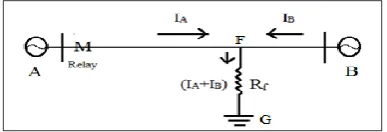
Distance relay failure due to infeed effect is explained in this section. Resistive fault in a transmission line fed from both sides is shown in Figure 3.
Figure 3. Effect of Infeed effect on Distance protection
The voltage drop in Rf will be Rf (IA+IB) which will influence the bus voltage at the relaying point while the current supplied to the relay will be only IA at A end.
Voltage seen by relay at A= Voltage across AF+ Voltage across FG
i.e. VA = (IA*ZAF)+ {(IA+IB)*RF} ……. (1)
Where ZAF is line impedance between point A and F. Current seen by the relay at A = IA,
Hence impedance seen by the relay Zf = VA / IA … (2)
Higher impedance seen by the relay than actual fault impedance is (IA / IB)*RF.
Thus the relay will under reach. that is the fault will appear to be electrically “further away” and may be outside the reach of Distance relay. In such cases the sequence components of voltage and current applicable at the relaying point have to be calculated and the impedance seen by the relay is determined from the formula of
Zk ……. (3)
Where I0 is the zero sequence current at the relay end.
III. POWER SYSTEM NETWORK DESIGN
AND SIMULATION OF FAULT CASES FOR A
400KV PRACTICAL SYSTEM
The network line diagram of the practical system showing 400kV protected line along with adjacent associated elements is considered as shown in Figure 4. The network diagram will indicate the voltage level, transformer /generator rated MVA & fault contributions of each element for 3-ph fault at station-A and for 3-ph fault at station-B [1]
Figure 4. Network line diagram of the protected line.
Equivalent representation of the protected line shown in Figure 4 is simplified and indicated in Figure 5 with equivalent source fault impedances at station-A and station-B, positive and zero sequence impedance of the protected line.
Line parameters
Line. Substation-A to Substation-B Frequency. 50Hz
Line data. R1 + jX1 = 0.0288 + j0.307 Ω/km R0 + jX0 = 0.2689 + j1.072 Ω/km R0M + jX0M = 0.228 + j0.662 Ω/km Line length. 190km
CT ratio. 1000/1A CVT ratio. 400/0.11kV
Maximum expected load on line both import and export. this shall be obtained from the load flow analysis of the power system under all possible contingency. From the load flow studies 1500MVA is the maximum expected load under worst contingency on this line at 90% system voltage.
Distance relay behavior during different types of single phase faults are simulated in Mipower software and explained below
1) Case-1. SLG Fault at 10% distance of the protected line with zero fault resistance
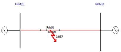
The equivalent system shown in Figure 5 is designed using Mipower tool, the line parameters used to design the model have been given. A SLG fault with zero fault resistance at 10% distance of the protected line is simulated using short circuit analysis as shown in Figure 6.
Figure 6. SLG fault at 10% distance of protected line with zero fault resistance
The quadrilateral characteristics of Zone-1 and Zone-2 with load encroachment and location of the fault impedance are indicated in R-X impedance diagram in below Figure 7.
Figure 7. Fault impedance location with distance protection characteristics - case 1
The location of the fault lies inside the operating region of quadrilateral characteristics and Distance protection trips effectively with no time delay for this case.
2) Case-2. SLG Fault at 10% distance with fault resistance of 50 ohm on the protected line
A SLG fault at 10% distance from bus-1 with fault resistance of 50 on the protected line is simulated using short circuit analysis and shown in Figure 8.
Figure 8. SLG fault at 10% distance with RF=50
The quadrilateral characteristics of Zone-1 and Zone-2 with load encroachment and location of the fault impedance for SLG HRF with fault resistance value of 50() are indicated in R-X impedance diagram in below Figure 9.
Figure 9. Fault impedance location with distance protection characteristics - case 2
3) Case-3. SLG Fault at 10% distance with fault resistance of 150 ohm on the protected line
A SLG fault at 10% distance at bus-1 with fault resistance of 150 on the protected line is simulated using short circuit analysis and shown in Figure 10.
Figure 10. SLG fault at 10% Distance with RF=150
In this case the fault impedance calculated using the fault current and post fault voltage at bus-1 lies far away from the operating region of Distance protection scheme, i.e. the relay fails to detect the high resistive faults. The quadrilateral characteristics of Zone-1 and Zone-2 with load encroachment and location of the fault impedance for SLG HRF with fault resistance value of 150() are indicated in R-X impedance diagram in below Figure 11.
Figure 11. Fault impedance location with distance protection characteristics - case 3
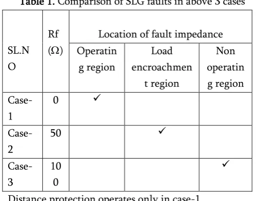
Table 1 gives the overall comparison of the SLG faults simulated in 3 cases to determine the operating characteristics of the Distance protection relay.
Table 1. Comparison of SLG faults in above 3 cases
SL.N
Distance protection operates only in case-1
IV.
FAILURE OF SCHEME COMMUNICATION
TO DETECT HIGH RESISTIVE FAULTS
Below are the scheme communications generally used in Distance protection of UHV and EHV transmission lines.
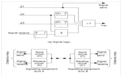
1) Direct Under-reach Transfer Tripping Scheme The simplest way of reducing the fault clearance time at the terminal that clears an end zone fault in Zone 2 time is to adopt a direct transfer trip or intertrip technique, the logic of which is shown in Figure 12. A contact operated by the Zone 1 relay element is arranged to send a signal to the remote relay requesting a trip. The scheme may be called a 'direct under-reach transfer tripping scheme‟, „transfer trip under-reaching scheme', or „intertripping under reach Distance protection scheme‟, as the Zone 1 relay elements do not cover the whole of the line. [4]
Figure 12. Logic for direct under reach transfer tripping scheme
2) Permissive Under-reach Transfer Tripping (PUP) Scheme
The direct under-reach transfer tripping scheme described above is made more secure by supervising the received signal with the operation of the Zone 2 relay element before allowing an instantaneous trip, as shown in Figure 13. The scheme is then known as a 'permissive under-reach transfer tripping scheme' (sometimes abbreviated as a PUTT, PUR or PUP Z2 scheme) or „permissive under reach Distance protection‟, as both relays must detect a fault before the remote end relay is permitted to trip in Zone 1 time. [4]
Figure 13. Permissive under-reach transfer tripping scheme
3) Permissive Over-reach Transfer Tripping (POP) Scheme
In this scheme, a Distance relay element set to reach beyond the remote end of the protected line is used to send an intertripping signal to the remote end. However, it is essential that the receive relay contact is monitored by a Directional relay contact to ensure that tripping does not take place unless the fault is within the protected section; see Figure 14. The instantaneous contacts of the Zone 2 unit are arranged to send the signal, and the received signal, supervised by Zone 2 operation, is used to energize the trip circuit. The scheme is then known as a 'permissive over-reach transfer tripping scheme' (sometimes abbreviated to POTT, POR or POP), 'Directional comparison scheme', or „permissive overreach Distance protection scheme‟. [4]
Figure 14. Permissive over-reach transfer tripping scheme
minimum time delay for improved protection of the transmission lines by reducing the fault clearance time at terminals to maintain the system stability. But all these scheme communication types fail to detect the high resistive faults on the transmission line because of the fault resistance location lying outside the operating zones of the Distance protection relay which doesn‟t initiate a carrier send signal as no zone starts in quadrilateral characteristics.
V.
DIRECTIONAL EARTH FAULT
PROTECTION FOR HIGH RESISTIVE FAULTS
As evident from the previous section of the paper, High resistive faults which occur frequently on transmission line are not able to be detected by Distance protection relay due to its condition for high resistance values in its R-X impedance diagram. Hence an alternative protection should be used for detection and clearance of high resistive faults on lines.
The alternative protection used in power system is Directional earth fault protection based on zero sequence currents in EHV and UHV transmission lines. It can also be used to provide a system back-up protection, for example, in case of the primary protection being out of service due to communication or voltage transformer circuit failure. The Directional earth fault relays can have an inverse or definite time delay characteristics and it can be set to Directional or non-Directional mode as per requirements. But as per grid standards it is recommended to use directional mode.
But the Directional earth fault protection is not a unit type protection which clears the fault without any time delay, i.e. the relay doesn‟t trip instantaneously. The time delay of Directional earth fault protection is generally coordinated with Zone-3 time delay of Distance protection and hence minimum time delay of Directional earth fault protection is 1.1sec as per power system protection
standards. But the Directional earth fault protection for high resistive faults will be much higher than 1.1 sec since fault current will be very low, which is not acceptable in high voltage transmission systems as high resistive fault in single phase imposes an increased voltage on other 2 healthy phases and
4) Effects of increased voltage on the 2 phases of HV transmission system
The effect of increase in other 2 phase voltages during HRF SLG fault in one phase may increase the air ionizing area around each phase of the line, which in turn increases the chance of arcing between the 2 phases or power conductor to ground. This effect is not acceptable in high voltage transmission systems as it may cause huge damage to the power line.
For HV transmission systems the insulator discs used are high in number based on voltage rating of the lines, for example. 400kV lines will have 25 insulator discs for providing proper insulation for the line. If the voltage rating of any phase increases above the maximum limit, the insulators on the line will be stressed and breakdown occurs which destroys the whole insulation system of the transmission line which is not acceptable for the power transmission line and causes a huge capital loss. In addition to the transmission line, other associated elements connected to the same substation may also get damage due to overvoltage, i.e. transformers, bus bars , reactors etc.
VI.
A NOVEL SOLUTION USING
DIRECTIONAL EARTH FAULT PROTECTION
AND SCHEME COMMUNICATION OF
DIRECTIONAL EARTH FAULT PROTECTION
From the discussion in the earlier sections, it is evident that Distance protection relay fails to detect the HRF and load resistive faults. The present protection system in India is compromised on Directional earth fault protection to clear HRF and load resistive fault which is a delayed protection and the fault cannot be cleared instantaneously.
A solution using Directional earth fault protection and scheme communication of Directional earth protection is an effective scheme to clear the HRF‟s and load resistive faults instantaneously. In this scheme if a SLG HRF occurs on one phase of the transmission line, start of Directional earth fault protection (67N) at one end will send carrier to remote end and vice-versa.
In the next step, local end Directional earth fault start is going to be ANDed with carrier received (Directional earth fault carrier) from remote end will be issued trip instantaneously as shown in Figure 16(a) & (b). Trip from both side Directional earth fault protections will be delayed based on fault current magnitude and relay settings but start of Directional earth fault at both ends will be instantaneous. Hence total time delay for trip during HRF‟s will be only PLCC communication delay (10 to 20ms)
Figure 15. Scheme communication of Directional earth fault protection
To incorporate this function in PCM software the
local end Directional earth fault protection start and remote end Directional earth fault protection start signal (CR=1) is given to AND logic, when both the input signals are high the Directional earth fault protection goes to instantaneous trip without any time delay at both the ends of the transmission line as shown in Figure 16.
Figure 16. (a) Logic block for scheme communication of Directional earth fault protection
Figure 16. (b) Logic block for scheme communication of Directional earth fault protection in PCM software
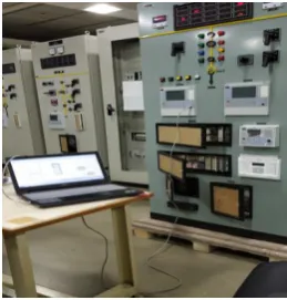
The prepared logic in PCM software is tested in the laboratory using ABB REL670 numerical relay and omicron injection unit which is used to inject the voltage and current values to the relay for testing as shown in Figure 17.
In present case the voltage and current values for injection are taken from a real disturbance at a 400kV transmission line where the Distance protection failed to operate. When the DR file received from the site is transplayed in laboratory, omicron injects the voltages and currents corresponding to disturbance took place in substation. Hence the behavior of numerical relay REL670 will be same as that of relay available at site.
The high resistive single line to ground fault was not cleared by Distance protection and hence Directional earth fault protection cleared this fault with a time delay of 750ms at the site. The test results were studied after the completion of testing process with the proposed solution. The study proved that the SLG HRF is instantaneously cleared by operation of Directional earth fault protection with scheme communication at both terminals of the transmission line.
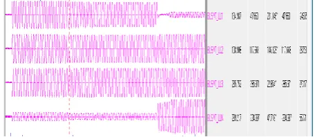
The phase currents and voltages of three phases and zero sequence currents during the incident at site where Directional earth fault protection cleared the fault in 750ms are shown in Figs 18 (a, b, c). The phase currents and voltages of three phases and zero sequence currents arrived during DR Transplay at laboratory are shown in Figs 19 (a, b, c).
Figure 18. (a) 3 phase analog current waveforms for SLG HRF
Figure 18. (b) 3 phase analog voltage waveforms for SLG HRF
Figure 18. (c) Binary trip signals initiated at SLG HRF
From Figure 18(c), it is evident that the Distance protection didn‟t start and the backup Directional earth fault protection started at 0s and issued trip command after 750ms which is generally not acceptable in 400kV transmission system.
Figure 19. (a) 3 phase analog current waveforms
for SLG HRF with logic
Figure 19. (c) Binary trip signals triggered at SLG HRF with logic
Figure 19(c) shows the trip signals initiated at the occurrence of SLG HRF, the Directional earth fault protection at local end starts instantaneously and sends a signal through PLCC to the remote end Directional earth fault protection. Both the start signals from local end and remote end gives a trip instantaneously to clear the SLG high resistive faults and load resistive faults to maintain the power system/grid stability in High voltage transmission lines.
VII.
CONCLUSION
A novel solution for clearance of High Resistive Faults in High Voltage transmission lines has been presented to detect and clear the single phase to ground HRF‟s instantaneously. Directional earth fault protection and scheme communication of Directional earth fault protection were used to develop the proposed logic to clear HRF‟s and load resistive faults. The proposed solution doesn‟t require any modification of panel wirings and cabling in field at substations and hence cost in-effective. This method is not affected by variations in fault location, fault inception angle, fault resistance, pre-fault load angle and line parameters. The solution is applicable for only SLG high resistive faults which are frequent and more in number. The proposed solution can be effectively used in national grids to clear single phase high resistive faults instantaneously with Directional earth fault protection and scheme communication.
VIII. REFERENCES
[1] „Task Force on Power System Analysis under Contingencies‟ Sub-committee ,Convener -B.S. Pandey, Power Grid ,Members - P. P. Francis, NTPC ,S.G. Patki, Tata Power ,R. H. Satpute,
MSETCL, Nagaraja, PRDC ,Bapuji Palki, ABB ,Vikas Saxena, Jindal Power
[2] Line Distance protection REL670 2.2 IEC, Technical manual-ABB
[3] „Task Force on Power System line setting calculations‟
[4] Network Protection & Automation Guide- Alstom Grid
[5] CIGRE- Modern Techniques for protecting and monitoring of transmission lines, 465-working group B5.07-June-2011
[6] CIGRE- Modern Distance protection functions and applications, 359-workinf group B5.15-October-2008