1
Failure Analysis of fractured Fixing Bolts of a Mobile Elevating Work Platform
using Finite Element Methods
2
Abstract
Mobile elevating work platforms (MEWPs) consist of a work platform, extending structure,
and chassis, and are used to move persons to working positions. MEWPs are useful but are
composed of pieces of equipment, and accidents do occur owing to equipment defects. Among
these defects, accidents caused by the fracture of bolts fixed to the extension structure and
swing system are increasing. This paper presents a failure analysis of the fixing bolts of MEWP.
Standard procedure for failure analysis was employed in this investigation. Visual inspection,
chemical analysis, tensile strength measurement, and finite element analysis (FEA) were used
to analyze the failure of the fixing bolts. Using this failure analysis approach, we found the root
cause of failure and proposed a means for solving this type of failure in the future. First, the
chemical composition of the fixing bolt is obtained by a spectroscopy chemical analysis method,
which determined that the chemical composition matched the required standard. The tensile
test showed that the tensile and yield strengths were within the required capacity. The stress
analysis was carried out at five different boom angles, and it was determined that the fixing
bolt of MEWP can withstand the loads at all the boom angles. The outcomes of the fatigue
analysis revealed that the fixing bolt fails before reaching the design requirements. The results
of the fatigue analysis showed primarily that the failure of the fixing bolt was due to fatigue. A
visual inspection of the fractured section of the fixing bolt also confirmed the fatigue failure.
We propose a method to prevent failure of the fixing bolt of the MEWP from four different
standpoints: the manufacturer, safety certification authority, safety inspection agency, and
owner.
Keywords: Fatigue Analysis, Finite Element Analysis(FEA), Mobile Elevating Work
3
1. Introduction
A mobile elevating work platform (MEWP) is a machine used for mobility. It moves persons
to working positions where they can carry out their work from the work platform, with the
intention that the workers board and disembark from the platform only at access positions at
the ground level or on the chassis. At a minimum, the MEWP consists of a work platform with
controls, an extending structure, and a chassis [1]. MEWP saves time and makes work at height
efficient, effective, and safer than using traditional methods of access. The use of MEWPs is
increasing as the benefits for productivity and safety are recognized. However, the increased
use of MEWPs in construction, maintenance, and other applications where trapping risks are
present has led to accidents in which people on the platform have been trapped between the
platform (often referred to as a cage or basket) and objects in the work area. In some cases,
these accidents have involved fatalities [2].
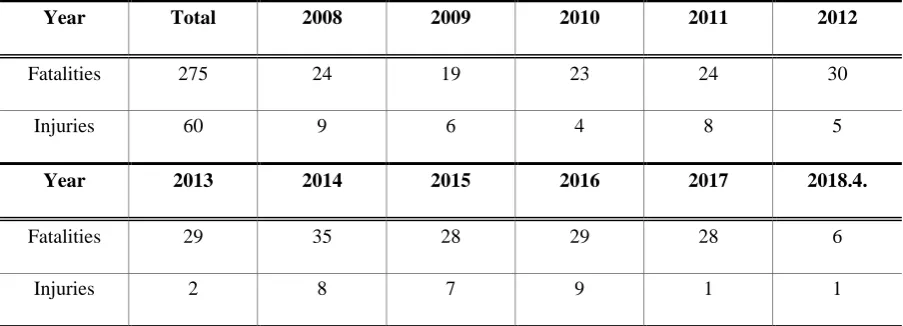
In Korea, unfortunately, a significant number of accidents involving the use of MEWPs have
occurred over the past 10 years, including tragic fatalities (Table 1). The number of accidents
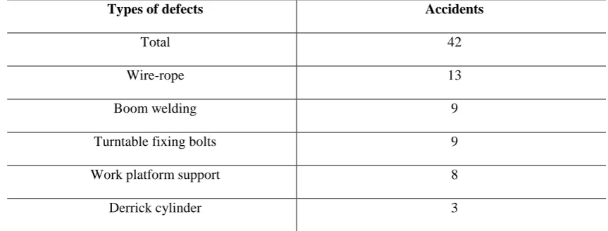
caused by mechanical defects is 42, and those caused by fixing bolt defects is 9, which is 21%
of the total (Table 2) [3].
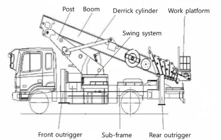
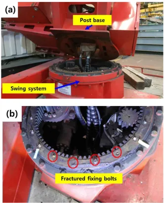
The failed MEWP of this study consists of a middle frame, X-shape front outrigger, rear
outrigger, turntable, 6-stage boom, one boarding work platform, and derrick cylinder, as shown
in Fig. 1. The main composition has various functions, such as left-right 360° operation (boom
rotation), withdrawal, and lead-in operation. These functions deal with the producer of oil
pressure power, which contains the oil pump and system. . The turntable was jointed
4
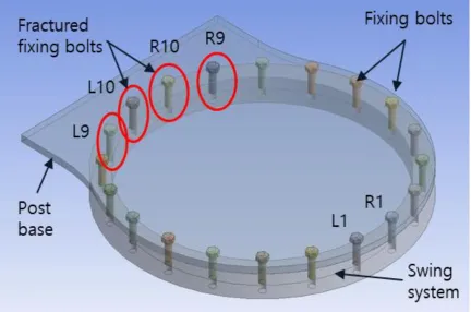
Out of these 20 bolts, 4 bolts were fractured [Fig. 2]. According to the information from the
customer, this MEWP failed after 40 months of service [Fig. 3]. Notably, none of the four
fractured bolts were accessible, and only one bolt (R10), which received the most loading, was
studied.
Several studies have been reported in the literature regarding the fracture of fixing bolts in
different engineering systems [4-9]. For example, in one of these case studies [4], addressing
the co-fracture of 16 connecting bolts of a filter press cylinder-piston system, it was concluded
that the bolts had failed owing to fatigue, apparently the result of insufficient torque used during
assembly. In another investigation [5], the fracture of worm-gear connecting bolts, due to
two-way bending fatigue, was reported. The main reason for the fracture was the large gap between
the bolts and their matching internal gear bolt holes, resulting from component wear.
Accordingly, failure analysis of the fractured fixing bolts to prevent similar failure accidents
was the main aim of the present study. Visual and material inspection, fracture mechanics, and
finite element analysis (FEA) of structure and fatigue were used to determine the main causes
5
2. Methods
To evaluate the material composition and mechanical properties of the fractured fixing bolts
of a MEWP, the mandatory tests of ISO 898-1 class 10.9 standard were performed [10]. For
this purpose, atomic absorption spectroscopy and tensile tests were performed according to the
ASTM E415 and ASTM A370 standards, respectively. The strength was measured according
to the instrumental indentation technique (using AIT-U made by FRONTICS) and the chemical
composition was determined by a spectroscopy chemical analysis method (using ARL iSpark
8880 made by Thermo Scientific).
Three-dimensional (3-D) finite element analysis (FEA) has been widely used for the
quantitative evaluation of stress in the critical zones of a structure. Therefore, in this study, a
well-known solid modeling software, SOLIDWORKS 2016 × 64 Edition, was used to design
the parts of the MEWP. Afterwards, these parts were imported to ANSYS 17.1 in the SLDPRT
format file. Finally, finite element modeling was proposed, and structural analysis and fatigue
6
3. Results and discussion
3.1. Physical testing and chemical analysis
3.1.1. Visual inspection
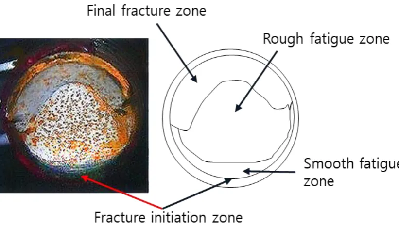
A visual inspection of the fractured section of the fixing bolt (R10) in the turntable revealed
characteristics of a fracture at the bolt thread near the contact part of the post base and swing
system. The fatigue crack appears to have propagated to the center of the bolt starting from the
thread, revealing three typical characteristics of fatigue failure—a smooth fatigue zone, rough
fatigue zone, and overload or final fracture zone at the fracture plane [5-7]. A schematic of the
fractured fixing bolt with specific zones is illustrated in Fig. 4.
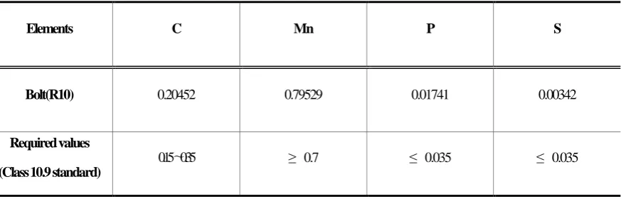
3.1.2. Chemical compositions analysis
Chemical composition analysis of the fractured fixing bolts was performed, and the results
are listed in Table 3 [8-9]. All the element properties of the bolts meet the technical
requirements of the class 10.9 standard.
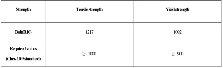
3.1.3. Tensile test
The tensile test results are presented in Table 4. The permissible values of ISO 898-1 for
class 10.9 mechanical properties are also included in this table [10]. In this regard, the tensile
7
3.2. Finite element model and boundary condition
3.2.1. Modeling
In this study, the height of the MEWP is 2985 mm, and it is equipped with a telescopic boom
of 16,000 mm maximum withdrawal when the boom angle is 0° and 28,000 mm when the
boom angle is 80° [12]. For structural and fatigue analysis of the turntable fixing bolts, as
shown in Fig. 5, a 3D model consisting of a swing system, post, and booms 1–6 was modeled
by SolidWorks. The 3D model was in the form in which the boom angle was increased by 20°
intervals from 0° to 80° within the working radius of the MEWP.
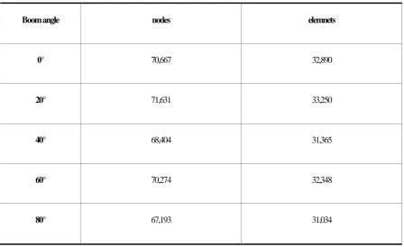
3.2.2. Mesh
To simplify the 3D shape for mesh work, unnecessary weld structures attached to the post
were removed, and mesh operations were performed. The type of element used is a tetrahedral
element, and the number of nodes and elements of the model according to each boom angle are
shown in Table 5, with the finite element model shown in Fig. 6.
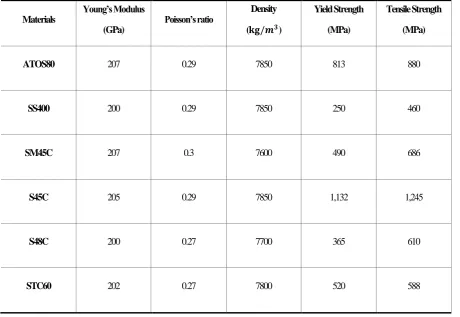
Among the components that make up the MEWP, the material of the pins and bushing are
SM45C, post base is SS400, booms 1–6 and the post are ATOS80, the fixing bolts are S45C,
the swing system is S48C, and the derrick cylinders are STC60. The properties of the material
are shown in Table 6 [13-15].
8
3.2.3. Boundary conditions
The load conditions are as follows. First, the bolt was torqued to the head of the bolt to
tighten the bolt; thus, a pretension value of 105,000 N was applied to the side of the bolt [16].
Second, the maximum load (3.9 kN) and the load of the workplatform (1.7 kN) was placed in
the direction of gravity at the end of boom 6. Finally, the gravity of the earth was considered
[17].
The boundary conditions of the structural analysis are shown in Fig. 7. The fixed support at
the lower end of the swing system was bonded to the post base, each boom and the
corresponding bolt head were bonded to the post base, the post base was bolted to the swing
system without separation, and the bolt side was bonded to the swing system, which was fully
engaged with thread. Each joint and pin served as a cylindrical support with a fully fixed radius
and axial direction, and the tangential direction was free [18].
For the fatigue analysis, the load condition and boundary condition were the same as those
in the previous structural analysis, and the S-N curve information of the fixing bolt (S45C) for
fatigue analysis was input in addition to the material properties [19-20]. The cyclic load
consisted of a sine-type zero-based load, and Goodman’s fatigue equation was applied [21-24]..
3.2.4. Result of structural analysis
The maximum von-Mises equivalent stress acting on the fixing bolt (R10) was obtained by
increasing the boom angle from 0° to 80° by 20° intervals according to the maximum work
radius of MEWP. The results of the structural analysis are shown in Fig. 8. The maximum
9
yield strength of fixing bolt, 1132 MPa, and the safety factor is 2.05, which is greater than the
MEWP design safety factor of 1.48 [25], confirming that the fixing bolt was designed safely.
3.2.5. Result of fatigue analysis
The finite element code of ANSYS Workbench was used to obtain the fatigue life, safety
factor, and damage distribution on the fixing bolt.
Fig. 9 represents the available life (number of cycles under constant loading conditions
before the fixing bolt fails owing to fatigue) for the given fatigue analysis. As the figure shows,
the minimum life (between 77,589 cycles and 83,443 cycles) has been determined for the zone
with the maximum von-Mises equivalent stress of the fixing bolt.
Fig. 10 indicates the fatigue damage, which is defined as the design life divided by the
available life. As this figure shows, the maximum damage (between 1.19 and 1.29) occurs at
the critical zones (a value greater than 1 indicates that the fixing bolt will fail from fatigue
before the design life is reached).
Fig. 11 represents the factor of safety (FS) with respect to fatigue failure at a given design
life. This value is valid between the minimum safe zones (0) and maximum safe zones (15). As
this figure shows, the minimum safety of the design (between 0.98 and 0.98516) designates the
10
4. Conclusions
The failure analysis of the fixing bolt of MEWP was investigated by visual inspection,
chemical composition analysis, tensile strength measurements, and FEA. The following
conclusions were drawn from the study.
1. The chemical composition of the fixing bolt was examined by the spectroscopy chemical
analysis method, which found that the chemical composition matched the required
standard.
2. The tensile test revealed that the tensile and yield strengths were within the required
capacity.
3. The stress analysis carried out at five different boom angles determined that the fixing
bolt of the MEWP can withstand the loads at all the boom angles. The results indicate
that the stresses in the fixing bolt are well within the safety limits, with a safety factor of
2.05.
4. The outcomes of the fatigue analysis revealed that the fixing bolt fails before reaching
the design requirements (fatigue life ≥ 100,000 cycles, safety of factor ≥ 1.0,
damage ≤ 1.0) [26], and the failure process (crack initiation – crack propagation –
fracture) starts at the zone with the maximum von-Mises equivalent stress.
The results of the fatigue analysis show that the fixing bolt may be damaged by fatigue if
MEWP is performed repeatedly for a long time. Therefore, we propose a method to prevent
the failure of the fixing bolt of the MEWP from four different standpoints— the manufacturer,
safety certification authority, safety inspection agency, and owner. The manufacturer should
11
authority should check the results of the fatigue analysis. In addition, the safety inspection
agency should inspect the crack through non-destructive means, and the owners should replace
the cracked fixing bolts and replace the entire fixing bolt set at regular intervals (e.g., 5 or 10
12
References
[1] Health and Safety Authority. Mobile Elevated Work Platforms Guidance on Safe Operating
Procedures.
[2] Strategic Forum for Construction. Best Practice Guidance for MEWPs Avoiding
Trapping/Crushing Injuries to People in the Platform.
[3] Accident Investigation Team. In-depth Analysis Report of the Accidents at the Mobile
Elevated Work Platform in the last 10 years. Ulsan (Korea): Korea Occupational Safety and
Health Agency; 2018. Report No.:2018-SAFETY-876. 38, 152 p. [in Korean].
[4] Sh. Molaei, R. Alizadeh, M. Attarian, Y. Jaferian. A failure analysis study on the fractured
connecting bolts of a filter press. Case Studies in Engineering Failure Analysis 2015; 4:
26-38.
[5] L. Li, R. Wang. Failure analysis on fracture of worm gear connecting bolts. Engineering
Failure Analysis 2014; 36: 439-46.
[6] S. D. Dalvi, Hariom, D. Chandrababu, S. Satav, Vijoykumar. Failure analysis of a carbon
steel roller shaft of continuous pad steam machine. Case Studies in Engineering Failure
analysis 2017; 9: 118-28.
[7] O. Asi. Failure of a stud bolt in a ring spinning frame textile machine. Engineering Failure
Analysis 2006; 13: 963-70.
[8] Z.-W. Yu, X.-L. Xu. Failure analysis on connection components of turbo-disk and
maim-shaft used in a locomotive turbocharger. Engineering Failure Analysis 2009; 16: 899-908.
[9] Z.-W. Yu, X.-L. Xu. Failure analysis of connecting bolts and location pins assembled on
the plate of main-shaft used in a locomotive turbocharger. Engineering Failure Analysis
2008; 15: 471-479.
[10] M. T. Milan, D. Spinelli, W. W. Bose Filho, M. F. V. Montezuma, V. Tita. Failure analysis
of a SAE 4340 steel locking bolt. Engineering Failure Analysis 2004; 11: 915-924.
[11] ISO 898-1. Mechanical properties of fastener made of carbon steel and alloy steel-Prat 1:
Bolts, screws and studs with specified property classes – Coarse thread and fine pitch thread.
2009.
13
[13] D. P. Hong, C. G. Park, B. K. Lee, Y. H., S. H. Hwang. Stress analysis for 46 kV insulated
boom design of 20 m-class high place operation car. Proceedings of the Korean Society for
Noise and Vibration Engineering 2012; 528-529.
[14] Online Materials Information Resource – MatWeb. http://www.matweb.com/
[15] T. Matsueda. An alternative method to evaluate endurance limit in plain steel specimens
(JIS, S15C S45C and A286). Applied Mechanics and Materials 2014; 563: 85-89.
[16] J. K. Kwon. Structural analysis of bolt. CAD&Graphic 2010; 12: 144-147.
[17] J. H. Lee, J. M. Hong. Structure analysis of boom joint for 2.5 ton class aerial lift truck.
The Korean Society for Precision Engineering Spring Conference 2017; 5: 586-587.
[18] J. M. Hong, J. H. Lee. Optimal design of boom joint for 2.5 ton class aerial lift truck.
Journal of the Korean Society for Precision Engineering 2018; 35: 769-775.
[19] G. H. Majzoobi, G. H. Farrahi, N. Habibi. Experimental evaluation of the effect of thread
pitch on fatigue life of bolts. International Journal of Fatigue 2005; 27: 189-196.
[20] S. Hanaki, M. Yamashita, H. Uchida, M. Zako. On stochastic evaluation of S-N data based
on fatigue strength distribution. International Journal of Fatigue 2010; 32: 605-609.
[21] K.-S. Nam, D.-W. Lee, J.-G. Choi, M.-H. Park, Z. Shang, S.-S. Lee. Structure and fatigue
analysis of pull-in winch frame using the FEA. The Korean Society of Mechanical Engineers
Spring Conference 2014 ;5: 363-365.
[22] J. H. Ko, D. M. Kang. CAE analysis on strength and fatigue of rear door of passenger car.
Journal of the Korean Society of Manufacturing Engineers 2014; 13: 63-69.
[23] Y.-J. Shin, C.-H. Choi, S.-G. Lee, J.-H. Kim. Fatigue CAE analysis of a rebar bending
machine roller. Journal of the Korean Society of Manufacturing Engineers 2015; 14: 75-80.
[24] D. Ozmen, M. Kurt, B. Ekici, Y. Kaynak. Static, dynamic and fatigue analysis of a
semi-automatic gun locking block. Engineering Failure Analysis 2009; 16: 2235-2244.
[25] ISO 8686-2. Crane-design principles for loads and load combinations – Part 2: Mobile
cranes. 2004.
[26] ISO 16368. Mobile elevating work platforms – Design calculations – Stability criteria –
14
Table 1. Number of injuries in the last 10 years*
Year Total 2008 2009 2010 2011 2012
Fatalities 275 24 19 23 24 30
Injuries 60 9 6 4 8 5
Year 2013 2014 2015 2016 2017 2018.4.
Fatalities 29 35 28 29 28 6
Injuries 2 8 7 9 1 1
* Note. Sourced and modified from KOSHA (2018-SAFETY-876). 2018. In-depth Analysis
Report of the Accident at the Mobile Elevating Work Platform in the last 10 years. Ch. 3. pp.
15
Table 2. Number of accidents caused by mechanical defects in the last 10 years*
Types of defects Accidents
Total 42
Wire-rope 13
Boom welding 9
Turntable fixing bolts 9
Work platform support 8
Derrick cylinder 3
* Note. Sourced and modified from KOSHA (2018-SAFETY-876). 2018. In-depth Analysis
Report of the Accident at the Mobile Elevating Work Platform in the last 10 years. Ch. 5. pp.
16
Table 3. Chemical composition analysis results of the fractured fixing bolt (mass, %)
Elements C Mn P S
Bolt(R10) 0.20452 0.79529 0.01741 0.00342
Required values
(Class 10.9 standard)
17
Table 4. Mechanical properties of the fractured fixing bolt (MPa)
Strength Tensile strength Yield strength
Bolt(R10) 1217 1092
Required values
(Class 10.9 standard)
18
Table 5. The number of nodes and elements of FEM according to boom angle
Boom angle nodes elemnets
0° 70,667 32,890
20° 71,631 33,250
40° 68,404 31,365
60° 70,274 32,348
19
Table 6. The mechanical properties used in structural analysis
Materials
Young’s Modulus
(GPa)
Poisson’s ratio Density (𝐤𝐠/𝒎𝟑)
Yield Strength
(MPa)
Tensile Strength
(MPa)
ATOS80 207 0.29 7850 813 880
SS400 200 0.29 7850 250 460
SM45C 207 0.3 7600 490 686
S45C 205 0.29 7850 1,132 1,245
S48C 200 0.27 7700 365 610
20
Fig. 1. Schematic of mobile elevating work platform working device*
* Note. Sourced and modified from HANSIN SPECIAL EQUIPMEMT CO. Instruction
21
22
Fig. 3. Failure scene of the fractured turntable fixing bolts: (a) turntable and boom after the
23
24
25
26
27
Fig. 8. Von Mises equivalent stress distribution on the fixing bolt according to boom angle
28
Fig. 9. Fatigue life simulations of the fixing bolt according to boom angle from 0° to 80°: (a)
29
Fig. 10. Fatigue damage contours of the fixing bolt according to boom angle from 0° to 80°:
30
Fig. 11. Minimum safety areas on the fixing bolt according to boom angle from 0° to 80°: