Design of Automatic Irrigation System using Arduino and IoT
M.V. Sudhakar
1, A.Kavya
2, M.Nagamalli
3, V.Bhavya
4, J. S.Susan
51
Professor,
2,3,4,5Student, Department of Electronics and Communication,
Lakireddy Balireddy College of Engineering, Mylavaram, India.
Abstract:
This project aims to aid the farmers in regulating their farms as they may not be able to keep an eye on them and moisten round the clock, so this renders such feasibility from their own residences. This proposed system also provides ease in their daily life. This is made possible by using Sensor Technology, IoT, Cloud memory and GSM module as a subsidiary in case the farmer fails to connect to the server. Initially the sensor acquires the information regarding the levels of soil moisture, then processed through arduino which is later stored in cloud memory. Farmer can retrieve this information and can perform actuations like switching on the motor as per the level of water required on his farm. Because of this automation, optimum utilisation of resources is achieved.
Keywords
Sensor Technology, Automation, Cloud Computing, IoT, GSM Module, Arduino.
1. Introduction
Agriculture is the basic source of food supply of all the countries of the world. The water taken up by the crops is totally provided through human intervention. In this process of irrigation, adaptation of trending technologies improves the growth and productivity. As of now, automation has gained a lot of importance in recent times in order to call any device as a "smart" one.
Automation can be defined as a technology concerned with performing a process by means of programmed commands combined with automatic feedback control to ensure proper execution of instructions. The resulting system is capable of operating without human intervention. The development of this technology has become increasingly dependent on usage of computing related technologies (computers, laptops, smart phones). This technology has matured to a point
where a number of other technologies have developed from it and have achieved recognition like ANN and SCADA. The recent one is IoT (Internet of Things) which has been implemented in the present proposed project.
Internet of Things is a computing concept that describes the connection of every physical object to Internet and thus this can improve the actual capabilities of the object. This concept is a network of everyday devices that are installed with required embedded system in order to get connected to other devices as well as Internet for the exchange of data. Things in IoT can refer to wide variety of devices, as of now they refer to the soil parameters in the current proposed system.
2. Literature Survey
to control irrigation pumps and sprinklers from far distance through a website and to meet the standard values. The disadvantages of this paper is no proper actuation is provided and also during the network unavailability this project is no use since it does not inform the conditions of the farm to the farmer residing at far distances from his farm.
3. Methodology
The proposed system contains four major blocks.
● Sensing block ● Processing block ● Actuating block ● Communicating block
Figure 1. Basic blocks in Proposed System
Sensing block:
The sensors used in this system are Soil Moisture sensor, Atmospheric temperature sensor and Magnetic sensor. The soil moisture sensor is used to know the amount of water content in the soil. The atmospheric temperature sensor measures the climatic temperature in the neighborhood of the crop field. The magnetic sensor is used to know the presence of the motor.
Data is collected from all these sensors and is given to the processing unit in order to perform the necessary actions on the soil according to the read parameter values.
Processing block:
This unit constitutes of a micro-controller which takes the outputs of sensors, processes and gives the information to actuation unit and communication unit. A code that converts the output voltage levels of sensors into actual parameter values has to be dumped into memory of the microcontroller. Based
on the information processed, necessary control signals have to be given to the actuation block and communication block.
Actuating block:
This unit comprises of a relay driver and a motor. The relay driver switches the motor on or off based on the controller output. Controller turns on the motor when the sensed moisture levels are below the lower threshold level. It turns the off the motor when the moisture levels reach the upper threshold level.
Communicating block:
The communicating block has two modes of transferring information to the owner of the farm. In the first mode, this block sends the status of the moisture level, the status of the motor whether it is in on state or off state as well as the presence of motor in the farm (motor theft condition) via SMS using GSM MODEM Module. The second mode of communication is to upload the information regarding the atmospheric temperature, soil moisture and the presence of motor using Wi-Fi Module and Router into Cloud memory.
4. Hardware Implementation
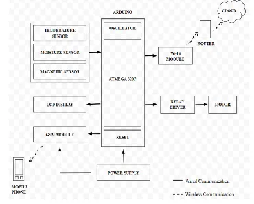
Figure 2 shows the block diagrammatic representation of entire hardware that is used in the proposed project. A detailed explanation of all the components is given in the latter paragraphs.
Figure 2. The Block diagrammatic representation of hardware components
Temperature Sensor (Thermistor):
A thermistor [6] is a special type of resistor which changes its physical resistance when exposed Sensing
Block
Processing Block
Actuating Block Communica
to changes in temperature. Thermistors are generally made from ceramic materials such as oxides of nickel, manganese or cobalt coated in glass which makes them easily damaged. The type of thermistor that are used in this system have a Negative Temperature Coefficient of resistance or (NTC), that is their resistance value goes down with an increase in the temperature. This thermistor measures the atmospheric temperature which can also be a parameter for soil humidity.
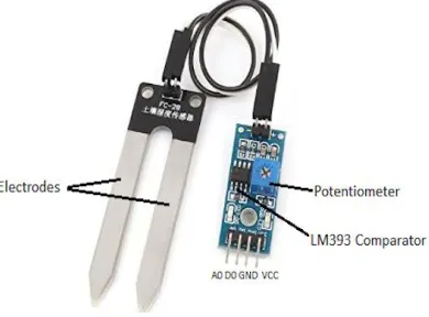
Soil Moisture Sensor (FC-28):
The soil moisture sensor FC-28[3] consists of two probes that are used to measure the volumetric content of water. The two probes allow the current to pass through the soil, which gives the resistance value to measure the moisture value. When there is water, the soil will conduct more electricity, which means that there will be less resistance. Dry soil conducts electricity poorly, so when there is less water, then the soil will conduct less electricity, which means that there will be more resistance. The specifications of the FC-28 soil moisture sensor are Input Voltage: 3.3–5V, Output Voltage: 0–4.2V, Input Current: 35mA, Output Signal: both analog and digital. The FC-28 soil moisture sensor has four pins as shown in the fig 4. The module also contains a potentiometer, which will set the threshold value. This threshold value will be compared by the LM393 comparator. The output LED will light up and down according to this threshold value.
Fig 3. FC-28 Soil Moisture Sensor
Magnetic Sensor (MC-38):
Magnetic Sensor (MC-38)[8]has a pair of magnetic materials. The two contacts are normally opened when there is no external magnetic field. If there is a small magnet near by the magnetic sensor makes the contacts to be short circuited this connected to the Opto-isolator. One of the magnetic strips is attached to the motor; the other strip is in contact with the prior strip. Whenever the magnetic strips are in contact, it indicates that the motor is in the field itself, the microcontroller receives bit 0. When an intruder tries to rob the motor, the strips get disconnected by the magnetic field, then the microcontroller receives bit 1.
Arduino:
Arduino[5] board contains ATMEGA328P microcontroller. This performs the key action of entire system ie. Processing of sensed data and initiating the necessary actions by giving control signals to the actuation unit. Initially the temperature sensor, soil moisture sensor and magnetic sensor give the sensed data in the form of voltages. Depending on the code that is dumped and executed the processing takes place. The code which is dumped into the arduino is C++. Along with the microcontroller, arduino has power supply (a combination of 12V-0-12V step down transformer and rectifying unit), LCD display, buzzer for indication a partial status of the system.
GSM Module (SIM900A MODEM):
Wi-Fi Module (ESP8266):
The ESP8266[9] is a low-cost serial module Wi-Fi microchip with a built-in TCP/IP stack and has the capability of connecting any small MC platform wirelessly to Internet. It has a 32-bit MC which works at 80MHz. It has 32 Kib instruction RAM and 80 Kib data RAM. It takes 3.3V DC supply. It uses AT commands to connect with WiFi networks and open TCP connections without the need to have TCP/IP stack running in our own microcontroller. It can simply connect any microcontroller to ESP module and start pushing data up to Internet.
Cloud (Thingspeak):
Cloud storage is a model of data storage in which the digital data is stored in logical pools, the physical storage spans multiple servers (and often locations), and the physical environment is typically owned and managed by a hosting company. These cloud storage providers are responsible for keeping the data available and accessible, and the physical environment protected and running. People and organizations buy or lease storage capacity from the providers to store user, organization, or application data. ThingSpeak[4] is an open source Internet of Things (IoT) application and API to store and retrieve data from things using the HTTP protocol over the Internet or via a Local Area Network. ThingSpeak enables the creation of sensor logging applications, location tracking applications, and a social network of things with status updates.
Figure 4. Entire Arrangement of Proposed System
Figure 5. On board connections for Arduino
5. Pseudo Code
The code is written in such a way that two threshold values are set, Lower Threshold Limit (LTL) and Upper Threshold Limit (UTL). If the soil moisture level falls below the UTL, relay driver turns the motor ON. The motor is in ON state itself until the soil moisture level reaches the UTL. Once the moisture level reaches UTL, motor goes to OFF state. The pseudo code for the actual code is shown below.
moist_level=0; //declaration and initialization of variable that has store soil moisture levels
LTL=50; //declaration and initialization of variable that has store Lower Threshold Level
UTL=135; //declaration and initialization of variable that has store Upper Threshold Level
processing of sensed values from FC-28
while (moist_level>UTL) //condition for off state of motor
{
Turn off the Motor;
}
{
Turn on the Motor;
}
When the moisture level once touches LTL, the motor is in ON state until it reaches UTL. When the moisture level once touches UTL, the motor is in OFF state until it reaches LTL.
The pseudo code for Theft condition of motor is,
motor_theft=0; //declaration and
initialization of variable that has store motor theft case
Processing of sensed values from the magnetic sensor MC-38
if (motor_theft=1) //condition for occurrence of motor theft
{
Send an SMS as well as update in the cloud storage that theft has occurred;
}
6. Results
The results of the proposed system are observed at three levels,
At the Soil In SMS
In Thingspeak platform At the Soil:
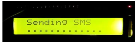
The 16x2 LCD display which has been incorporated in the project displays the atmospheric temperature and soil moisture levels at the soil level. Also the status of GSM module while it is sending an SMS is also displayed in the LCD display. This is better understood by below figures.
Figure 6. Indication of Atmospheric temperature and Soil moisture in 16x2 LCD display
Figure 7. Indication of status of GSM module while sending SMS
In SMS:
This level uses a mobile phone set to know the status of soil moisture and motor. Messages are sent to mobile of farmer when the soil moisture falls below LTL, and when the soil moisture reaches to a value above UTL. Also alert messages are sent in the case of motor theft. The following screenshots depict the results observed in the farmer’s mobile phone set using GSM module.
Figure 8. SMS showing moisture below LTL
Figure 9. SMS showing moisture above UTL
Figure 10. SMS showing motor theft case
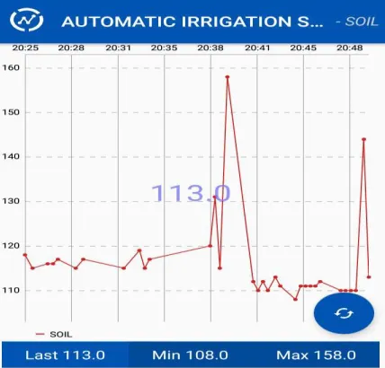
In Thingspeak platform:
values in the cloud are clearly understood by using the below figures.
Figure 11. Atmospheric temperature values vs Time
Figure 12. Soil Moisture Values vs Time
Figure 13. Motor Theft Values vs Time
7. Conclusion
The proposed method helps in monitoring the farm and controlling the moisture levels automatically. This system reduces the efforts of the farmer and makes his life easy. The system is a bit more efficient than the previous methods that have been proposed till date. It is because of the feature that the system is capable of detecting the absence of motor. Also the system constantly updates the farmer about the status of the soil and irrigation system. Hence this paper helps in introducing an efficient system to enhance the way the farmers have been monitoring their farm.
8. References
[1] M.Priyadharsini, V.Arunbalaji and T.Karthikaa, GSM Based Motor Control for Irrigation System, International Journal of Advanced Research in Electrical, Electronics and Instrumentation Engineering, Volume 5, Special Issue 1, March 2016.
[2]Pushkar Singh and Sanghamitra Saikia, Humanitarian Technology Conference (R10 – HTC) Agra, India, 2016.
[3]
https://www.google.co.in/search?q=fc-28+soil+moisture+sensor&source=lnms&tbm=isch& sa=X&ved=0ahUKEwjs5cmIs5naAhWJRo8KHYhv BdIQ_AUICigB&biw=1396&bih=625#imgrc=kJngv FffQKtmUM:
[5]https://en.wikipedia.org/wiki/Arduino
[6]https://www.google.co.in/search?q=thermistor&so urce=lnms&tbm=isch&sa=X&ved=0ahUKEwiy-tSqtpnaAhVEuI8KHT1yCAcQ_AUICigB&biw=139 6&bih=625#imgrc=61lC3UlZePaZKM:
[7]https://www.google.co.in/search?q=thermistor&so
urce=lnms&tbm=isch&sa=X&ved=0ahUKEwiy-tSqtpnaAhVEuI8KHT1yCAcQ_AUICigB&biw=139 6&bih=625#imgrc=61lC3UlZePaZKM
[8]https://en.wikipedia.org/wiki/GSM