A CLONAL SELECTION ALGORITHM FOR ARRAY PATTERN NULLING BY CONTROLLING THE POSITIONS OF SELECTED ELEMENTS
B. Babayigit
Department of Computer Engineering Faculty of Engineering
Erciyes University 38039, Kayseri, Turkey
K. Guney andA. Akdagli
Department of Electrical andElectronics Engineering Faculty of Engineering
Erciyes University 38039, Kayseri, Turkey
Abstract—In this paper, a methodbasedon clonal selection
algorithm (CLONALG) is proposedfor null steering of linear antenna arrays by controlling only the positions of selectedelements. The CLONALG is a relatively novel population-basedevolutionary algorithm inspiredby the clonal selection principle of the human immune system. In order to illustrate the accuracy and flexibility of the proposedalgorithm, several numerical examples of Chebyshev pattern with the single anddouble nulls imposedat the directions of interference are given.
1. INTRODUCTION
(amplitude and/or phase) and positions of array elements. These null steering techniques have been usedwith their own benefits and limitations in the antenna array pattern nulling.
It is well known that the classical optimization techniques are likely to be stuck in local minima if the initial guesses are not reasonably close to the final solution. The most of the classical optimization techniques andanalytical approaches also suffer from the lack of producing flexible solutions for a given antenna pattern synthesis problem. The disadvantages of the classical andanalytical techniques andrapiddevelopment of computer technologies in recent years have encouragedthe researcher to use the evolutionary optimization algorithms basedon computational intelligence methodologies. It was shown that the evolutionary optimization techniques such as the genetic algorithm [3], ant colony optimization [4], particle swarm optimization [5] anddifferential evolution [6] are capable of performing the better andmore flexible solutions than the classical optimization techniques andthe conventional analytical approaches.
The position only methods require a mechanical driving system such as servomotors to move every element in the array. When the number of elements in the array increases, the computational time to findthe new position perturbations will also increase along with the number of mobilizedelements in the array. To reduce the number of mobilizedelements in the array andto effectively increase the array robustness, the methodof controlling only the positions of selected elements is preferred[7].
In this paper, a methodbasedon CLONALG [8] is presented to steer single and double nulls to the directions of interference by controlling only the positions of selectedantenna array elements. The CLONALG is a simple population-basedevolutionary algorithm inspiredby the clonal selection principle [9] of the human immune system. The CLONALG has some distinguished features. It operates on a population of points in search space simultaneously, not on just one point, does not use the derivatives or any other information, and employs probabilistic transition rules insteadof deterministic ones. It also has the ability of getting out local minima. As a relatively novel optimization algorithm, the CLONALG has been successfully applied to solve various engineering problems [8, 10–15].
2. PROBLEM FORMULATION
situatedandexcitedaroundthe center of the linear array, the far field array factor of such an array is real, andit can be written as
F(θ) = 2
N
k=1
akcos
2π
λ dksinθ
(1)
whereλis the wavelength, θis the scanning angle from broadside, ak
is the amplitude of the kth element, and dk is the distance between
position of the kth element andthe array center. The contribution of each element position of the array to the null locations is calculated by replacing dk given in Eq. (1) by dk+δk where δk is the position
perturbation of the kth element. In order to find an optimal set of element position values that achieves the desired nulling performance, the following cost function will be minimizedby using the CLONALG
C=
90◦
θ=−90◦
[W(θ)|Fo(θ)−Fd(θ)|+ESL(θ)] (2)
whereFo(θ) andFd(θ) are, respectively, the pattern obtainedby using
CLONALG andthe desiredpattern. W(θ) andESL(θ) are included in the cost function to control the null depth level and maximum sidelobe level, respectively.
3. CLONAL SELECTION ALGORITHM
3.1. Human Immune System (IS)
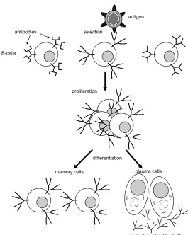
Figure 1. The clonal selection principle.
3.2. Clonal Selection Principle
new cells to match the antigen more closely. The B-cells with high affinities are selected to differentiate into memory cells which do not secret antibodies but instead remember the antigenic pattern. The B-cells that are not stimulatedas they do not match any antigens in the human body will eventually die.
Once the body has successfully defended against an antigen, memory cells remain andcirculate in the blood, lymph, andtissues for very long periods of time. When the same or similar antigen is encounteredin the future, memory cells are stimulatedandmore abundant production of antibodies is observed.
3.3. Clonal Selection Algorithm (CLONALG)
The CLONALG [8] inspiredby the clonal selection principle [9] of the human IS is a newly discovered, high-performance evolutionary algorithm capable of solving general N-dimensional, linear and nonlinear optimization problems [8, 10–15]. The concept of the CLONALG is shown in Fig. 2.
BEGIN
Construct the initial population of antibodies REPEAT
Evaluate antibodies to calculate their affinities Select the n best affinity antibodies and clone them Maturate the clones and evaluate them
Allow the best antibody from each subpopulation to survive
Replace the d lowest affinity antibodies with new antibodies randomly produced UNTIL A termination criterion is satisfied or the maximum generation number is reached END
Figure 2. A simple CLONALG.
The CLONALG starts by randomly generating the initial population (Npop) of antibodies in a given bounds for the problem
considered. Each antibody which means a candidate solution is representedby a binary string of bits. The bit string length is suitably selectedby the user corresponding to the problem for obtaining a reasonable precision. The antibodies are evaluated over an affinity (fitness) function and ranked in decreasing order of affinity. The first nantibodies are selected for cloning operation. The number of clones generatedfor all thesenselectedantibodies is given by
Nc = m
i=1
round
βNpop
i
(3)
operation, the clones are subject to a hypermutation process inversely proportional to their affinity; the higher the affinity the smaller the mutation rate. Hence, the mutation rate of a clone is inversely proportional to the fitness of its parent. The antibodies in each subpopulation which consists of the parent andits clones maturated by hypermutation operation are then evaluatedin the affinity function, andthe best antibody of each subpopulation becomes memory cell andis allowedto survive. The antibodies with d lowest affinities are replaced by the new antibodies generated randomly to maintain the diversity of antibody population so that the new areas of the search space can be potentially explored. The next generation starts with a new antibody population produced as described above. These processes are repeateduntil a termination criterion is attainedor a predetermined generation number is reached. A very clear overview of the clonal selection principle andthe CLONALG, from immunology andengineering points of view, can be foundin [8].
4. NUMERICAL RESULTS
In order to illustrate the effectiveness and flexibility of the proposed CLONALG, two examples are presented. In the examples, a 30-dB Chebyshev pattern for 20 equispacedelements with an interelement spacing of 0.5λ was usedas the initial pattern. The affinity value of the antibodies in CLONALG is calculated by
AF F = 1
1 +C (4)
The population size of the antibodies (Npop) andthe number of
iteration are, respectively, selectedas 70 and150, andeach antibody is representedby a string of 16 bits. The typical CLONALG parameter values of n, β, and d are set to 40, 2, and30, respectively. The simulation results are obtainedwithin 2–3 minutes on a personal computer with a Pentium IV processor running at 2400 MHz. In all of the examples, the cost function parameters given in Eq. (2) are chosen as
Fd(θ) =
0, for θ=θi
Initial Chebyshev pattern, elsewhere (5)
W(θ) =
100, for θ=θi
1, elsewhere (6)
ESL(θ) =
5, ifM SL(θ)>−28 dB
whereMSL given in Eq. (7) represents the maximum sidelobe level of achievedpattern in the sidelobe region.
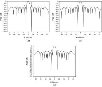
In the first example, a single null imposedat the direction of the secondpeak (θi = 14◦) from the main beam of the Chebyshev pattern
is considered. The achieved patterns produced by the CLONALG are illustratedin Figs. 3(a), (b), and(c) when the positions of all elements, the selected14 and12 elements of the array are perturbed, respectively. As can be seen from Fig. 3 that all desired nulls are deeper than 115 dB. The position perturbations obtainedby the CLONALG to produce the patterns in Fig. 3 are listedin Table 1. The position perturbations given in Table 1 are usedto findthe significance of each element to the null locations andconsequently findthe number of controlledelements. The methodproposedhere freezes the positions of the element that have insignificant contributions to the nulls.
(degree)
-80 -60 -40 -20 0 20 40 60 80
IF ( )I ( d B ) -150 -140 -130 -120 -110 -100 -90 -80 -70 -60 -50 -40 -30 -20 -10 0 (degree)
-80 -60 -40 -20 0 20 40 60 80
IF(
)I (d
B) -150 -140 -130 -120 -110 -100 -90 -80 -70 -60 -50 -40 -30 -20 -10 0
(a) (b)
(degree)
-80 -60 -40 -20 0 20 40 60 80
IF( )I (dB) -150 -140 -130 -120 -110 -100 -90 -80 -70 -60 -50 -40 -30 -20 -10 0 (c) θ θ θ θ θ θ
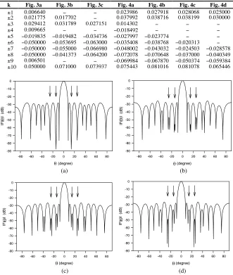
Table 1. Element position perturbations (δk) in λ for Figs. 3 and4
obtainedby using CLONALG.
k Fig. 3a Fig. 3b Fig. 3c Fig. 4a Fig. 4b Fig. 4c Fig. 4d
±1 0.006640 − − 0.023986 0.027918 0.028068 0.025000 ±2 0.021775 0.017702 − 0.037992 0.038716 0.038199 0.030000 ±3 0.029412 0.031789 0.027151 0.014302 − − −
±4 0.009665 − − −0.018492 − − −
±5 −0.019835 −0.019482 −0.034736 −0.027997 −0.023774 − − ±6 −0.050000 −0.053695 −0.063000 −0.035408 −0.038768 −0.020313 − ±7 −0.050000 −0.055000 −0.066980 −0.048002 −0.043032 −0.024503 −0.028578 ±8 −0.050000 −0.041373 −0.064200 −0.072078 −0.070648 −0.037000 −0.040349 ±9 0.006501 − − −0.069984 −0.067870 −0.050374 −0.059384 ±10 0.050000 0.071000 0.073937 0.075443 0.081016 0.081078 0.065446
(degree)
-80 -60 -40 -20 0 20 40 60 80
IF(
)I (d
B ) -90 -80 -70 -60 -50 -40 -30 -20 -10 0 (degree)
-80 -60 -40 -20 0 20 40 60 80
IF( )I (dB ) -90 -80 -70 -60 -50 -40 -30 -20 -10 0
(a) (b)
(degree)
-80 -60 -40 -20 0 20 40 60 80
IF ( )I (d B) -90 -80 -70 -60 -50 -40 -30 -20 -10 0 (degree)
-80 -60 -40 -20 0 20 40 60 80
IF(
)I (dB)
-90 -80 -70 -60 -50 -40 -30 -20 -10 0
(c) (d)
θ θ
θ θ
θ θ
θ θ
Figure 4. Radiation pattern with double nulls imposed at 14◦ and 25◦ obtainedby using the position perturbations for (a) 20 elements, (b) 16 elements, (c) 14 elements, and(d) 12 elements.
and θi2 = 25◦) from the main beam is considered. The resulting
patterns obtainedby the CLONALG are shown in Figs. 4(a), (b), (c), and(d) when the positions of all elements, the selected16, 14 and12 elements of the array are perturbed, respectively. The corresponding position perturbations of the array elements are given in Table 1.
It is apparent from Figs. 3 and4 that the patterns are symmetric with respect to the main beam. This is because the symmetry property of the element positions aroundthe array center results in a pattern that is symmetric about the main beam. Therefore, when a null imposedat the one side of the main beam, an image null occurs at the other side of the main beam. The results depicted in Figs. 3 and4 show that the CLONALG proposedin this work can accurately obtain the nulling patterns by controlling only the selectedelement positions of the linear array. From the null depth and the maximum sidelobe level points of view, the performances of the patterns are also very good. Furthermore, the nulling technique based on CLONALG preserves the characteristics of the initial Chebyshev pattern with little pattern disturbance except for the nulling directions.
5. CONCLUSION
A new technique basedon the CLONALG is presentedfor null steering of linear antenna arrays by controlling only the positions of selected elements. Numerical results show that the algorithm can obtain the patterns with satisfactory null depth and maximum sidelobe level. It is worth noting that even though the CLONALG presentedhere is usedto a particular synthesis of linear array with isotropic elements, it can easily be implementedto nonisotropic-elements antenna arrays with different geometries for the design of various array patterns. We hope that the CLONALG can be very useful to antenna engineers for the pattern synthesis of antenna arrays since it has goodaccuracy and does not require complicated mathematical functions.
REFERENCES
1. Balanis, C. A.,Antenna Theory: Analysis and Design, John Wiley andSons, 1982.
2. Mailloux, R. J., Phased Array Antenna Handbook, Artech House, Boston, 1994.
3. Liao, W. P. andF. L. Chu, “Array pattern nulling by phase and position perturbations with the use of the genetic algorithm,”
4. Karaboga, D., K. Guney, andA. Akdagli, “Antenna array pattern nulling by controlling both the amplitude and phase using modified touring ant colony optimization algorithm,” Int. J. Electron., Vol. 91, 241–251, 2004.
5. Khodier, M. M. and C. G. Christodoulou, “Linear array geometry synthesis with minimum sidelobe level and null control using particle swarm optimization,” IEEE Trans. Antennas Propagat., Vol. 53, 2674–2679, 2005.
6. Yang, S., Y. B. Gan, andA. Qing, “Antenna-array pattern nulling using a differential evolution algorithm,” Int. J. RF Microwave Computer Aided. Eng., Vol. 14, 57–63, 2004.
7. Hejres, J. A., “Null steering in phasedarrays by controlling the positions of selectedelements,”IEEE Trans. Antennas Propagat., Vol. 52, 2891–2895, 2004.
8. De Castro, L. N. andF. J. Von Zuben, “Learning andoptimization using the clonal selection principle,”IEEE Trans. Evol. Comput., Vol. 6, 239–251, 2002.
9. Ada, G. L. and G. Nossal, “The clonal selection theory,”Scientific American, Vol. 257, 50–57, 1987.
10. Campelo, F., F. G. Guimaraes, H. Igarashi, andJ. A. Ramirez, “A clonal selection algorithm for optimization in electromagnetics,”
IEEE Trans. Magnetics, Vol. 41, 1736–1739, 2005.
11. Babayigit, B., A. Akdagli, and K. Guney, “A clonal selection algorithm for null synthesizing of linear antenna arrays by amplitude control,” Journal of Electromagnetic Waves and Application, Vol. 20, 1007–1020, 2006.
12. Akdagli, A., K. Guney, and B. Babayigit, “Clonal selection algorithm for design of reconfigurable antenna array with discrete phase shifters,” Journal of Electromagnetic Waves and Application, Vol. 21, 215–227, 2007.
13. Zhang, L., Y. Zhong, B. Huang, J. Gong, andP. Li, “Dimensional-ity reduction based on clonal selection for hyperspectral imagery,”
IEEE Trans. Geosci. Remote Sens., Vol. 45, 4172–4186, 2007. 14. Dong, W., G. Shi, andL. Zhang, “Immune memory clonal
selection algorithms for designing stack filters,” Neurocomputing, Vol. 70, 777–784, 2007.