Stepped Slot Patch Antenna with Copper Ground Plane and Solar
Cell Ground Plane for Future Mobile Communications
Thandullu N. Suresh Babu1, * and Dhandapani Sivakumar2
Abstract—A new structure design of a multi-band suspended stepped slot microstrip patch antenna with copper ground plane for future mobile communications is proposed and presented. A parametric study for the effect on the proposed antenna is done on a par with the integration of a polycrystalline silicon solar cell. The compact low profile proposed antenna is developed using Printed Circuit Board (PCB) technology on a substrate, FR4 with physical size of 50×50 mm2. Simulated and measured results are presented to validate the usefulness of the proposed antenna structure for Wi-Max and future mobile communications. The measured result reveals that the presented stepped slot patch antenna with copper ground plane offers impedance bandwidth of 3.94% (covering 5.46 GHz–5.68 GHz band), 3.06% (covering 7.08 GHz–7.3 GHz band), and 9.26% (covering 8.34 GHz–9.15 GHz band). The same radiating patch with solar ground plane offers impedance bandwidth of 4.58% (covering 5.12 GHz– 5.36 GHz band) and 3.06% (covering 7.32 GHz–8.02 GHz band) for future mobile communications. Good VSWR and radiation pattern characteristics are obtained in the frequency band of interest.
1. INTRODUCTION
Today’s communication is mainly human-driven, but in future communications, a large number of machines will communicate with each other and with humans which have ambitious objectives in terms of performance and quality of service lofty expectations from consumers, developers, and businesses for 5th-generation (5G) wireless technology. Spectrum shortage problem occurs because the number of wireless users is increased. Thus, high-SHF (above 6 GHz) is today’s innovative frontier for emerging wireless mobile cellular networks, wireless local and personal area networks, simultaneous energy/data transfer, wearable networks, vehicular communications, and radar. In order to satisfy future expected requirements, such as super high bit rate, above 6 GHz bands are very attractive because wider frequency bandwidth is relatively easily obtained.
By considering the increase of low cost, compactness of electronic systems, and a need of embedding two or more narrowband systems together, microstrip patch antennas are most widely used in modern communication systems, because of their several advantages such as light weight, low volume, low fabrication cost, and capability of dual, triple, and more frequency operations. However, microstrip patch antennas have several limitations like narrow bandwidth, low efficiency, low gain, low power handling capacity, spurious feed radiation, and inherently low impedance bandwidth. To overcome these inherent limitations of microstrip antennas, slots are used for improving the characteristics like broadband operation, gain enhancement, side lobe level reduction, and radiation pattern stabilization with multiband operation.
For future mobile communication, 5G needs a spectrum within three key frequency ranges to deliver widespread coverage and support all use cases. The three ranges are: Sub-1 GHz, 1–6 GHz, and above
Received 16 October 2019, Accepted 15 December 2019, Scheduled 6 January 2020 * Corresponding author: Thandullu Naganathan Suresh Babu ([email protected]).
1 ECE Department, Adhiparasakthi Engineering College, Melmaruvathur, Tamilnadu 603319, India. 2 ECE Department, Eswari
is presented [4] by cutting U-slots in the patch for broadband operation. A set of slots including pi, triangular, and circular slots is presented, which can be used to enhance the gain of the patch antenna, reduce side lobe levels, and/or stabilize the radiation patterns by removing null from broadside [5].
By incorporating a triangular notch and parasitic slots, a wide slot antenna with a Y shape tuning element is presented [6] for wireless applications (GSM 1800, WiMAX, PCS, and ITM-2000). A novel single probe-fed, single-layer, and single-patch triple-band microstrip antenna is presented [7], by incorporating two identical U-slots in the patch, which can resonate for WLAN 2.4 GHz, WLAN 5.8 GHz, and 3.5 GHz of 5G (the fifth-generation mobile communication) operation. A modified π-shaped slot loaded multifrequency microstrip antenna is presented [8] and resonates at 3.3, 4.55, 5.56, and 6.08 GHz in microwave S and C bands. A compact low-profile and quad-band antenna with three differently shaped slots, suitable to be integrated with a portable device for varieties of wireless communication applications is presented [9] and covers frequency bands from 2.39 to 2.48 GHz for lower WLAN, 3.64– 3.73 GHz for downlink, and 5.98–6.30 GHz for uplink standard satellite communications, and 6.97– 7.18 GHz mainly used by the Indian National Satellite System. A low-profile and broadband slot antenna with artificial magnetic conductor (AMC) surface is designed [10] for X and Ku communication, which improves the radiation and impedance matching properties of the broadband slot antenna. A trident shape ultra-large band fractal slot EBG antenna is presented [11], and it is highly compatible with various wireless devices associated with IoT based wireless application between the ranges of 1.59 and 13.31 GHz frequencies.
Solar energy fetching is alluring and alternative to powering autonomous communication systems. These devices often involve the use of separate photovoltaic (PV) cells and antennas, which demand a compromise in the utilization of the limited space available. The solar cells act as a ground plane, in addition to their function as a power source and can also be integrated with microwave patch antennas [14–17].
A simple and compact design of a slot patch antenna integrated on an amorphous silicon solar cell for dual band (2.4/5.2 GHz) wireless local area network applications is proposed [18]. A transparent patch antenna on a-Si thin-film glass solar module [19] and solar cell stacked dual-polarized patch antenna module [20] is presented for WiMAX applications. The integration of slot antennas in a class of commercial photovoltaic (PV) solar panels are proposed for stand-alone communication systems operating in the GSM/UMTS and WiMAX frequency bands [21]. A poly-Si solar cell stacked self-complementary shaped multiple-L slot loaded suspended microstrip patch antenna is presented [22] for 2.4/5.2 GHz band WLAN and 2.5/3.3/5.8 GHz band WiMAX networks. A patch antenna integrated on the cover glass of a commercial space-certified solar cell [23] is studied. A wideband integrated photovoltaic (PV) solar cell patch antenna [24] for 5 GHz Wi-Fi communication is presented and discussed. A parametric study presented for the effect of the antenna is done on a par with the integration of the polycrystalline silicon solar cell for above 6 GHz satellite applications [25, 26]. This integration of microwave antennas and PV technology on the same surface has led to the development of self-powered integrated systems that can be configured by a variety of design techniques and can help to reduce the weight and peripheral expense of the system.
microstrip antennas with constant gain over the wide frequency range. In this paper, a multi-band suspended stepped slot patch antenna with ground plane of both copper and solar cell is presented and serves as 5G for future mobile communications. Simulations of the design with HFSS (High Frequency Structure Simulator) Software show promising results. This paper is structured as follows. Section 2 describes the design, parameters, and geometry of a microstrip patch with specifications. Section 3 shows the results explaining antenna parameters like return loss, VSWR, and gain. Finally, Section 4 shows the conclusion.
2. STEPPED SLOT PATCH ANTENNA DESIGN AND FABRICATION
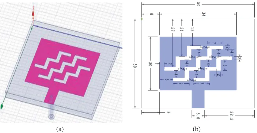
The proposed stepped slot patch antenna with dimensions of 50 mm×50 mm×1.6 mm together with the feeding structure is designed using HFSS as shown in Fig. 1(a). The antenna is developed on an FR4 epoxy substrate with relative dielectric constant ofεr4.4, loss tangent of 0.02, and height of 1.6 mm, with a copper ground plane on the lower side of the substrate. In this design, the overall patch dimensions are determined based on the transmission line model for designing a solid patch to operate at the desired frequency [12, 13]. The patch antenna comprises a length of the said antenna about 30 mm, and width of the said antenna is 34 mm while the said stepped slots are arranged at the center of the said patch with spaced intervals according to a direction of radiation of the said patch antenna. The plurality of slots has a length of 7 mm, height of 8 mm, and width of 2 mm. The said plurality of first, second, and third elongated stepped slots are arranged in parallel to each other. The said first elongated stepped slots and second elongated stepped slots are separated by a distance of vertically 4 mm and horizontally 2 mm. Similarly, the second elongated stepped slots and the third elongated stepped slots are separated by a distance of vertically 4 mm and horizontally 2 mm. The said ground radiating copper plane and the patch are fed by a microstrip line shown in Fig. 1(b). For improving the impedance matching, a coaxial power feed is connected at a pre-determined location on microstrip line.
(a) (b)
Figure 1. Stepped slot microstrip patch antenna. (a) Overall view in HFSS. (b) Geometry of the proposed patch.
(a) (b)
Figure 2. Fabricated proposed solar cell integrated stepped slot patch antenna. (a) Front view. (b) Back side view.
3. SIMULATION AND MEASUREMENT RESULTS
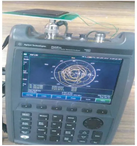
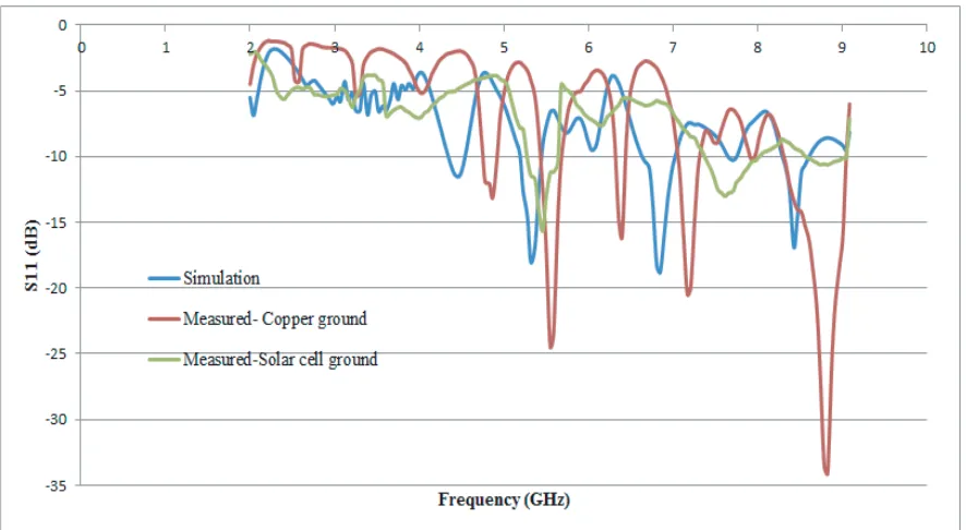
The VNA antenna measurement setup model is shown in Fig. 3. The simulated and measured return losses S11 versus frequency and VSWRs versus frequency of the proposed antenna are illustrated in Fig. 4 and Fig. 5. It is evident in Fig. 4 and Fig. 5 that there are multi-resonances, each providing broad bandwidth according to the simulation and practical results. The simulated results are carried out using HFSS and show thatS11response of better than−10 dB is achievable over 5.2 GHz–5.43 GHz, 6.8 GHz–7.04 GHz, and 8.3 GHz-8.61 GHz bands with VSWR less than 2. An Agilent network analyzer and coaxial calibration standard are used to conduct measurements on the prototype. The measuredS11
Figure 4. Return loss (S11) versus frequency.
Figure 5. VSWR versus frequency.
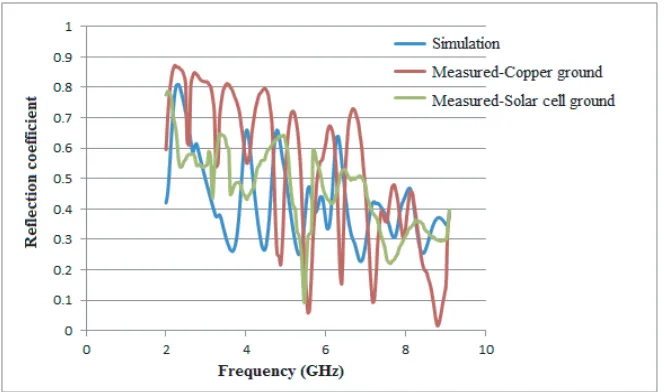
Figure 6. Reflection coefficient versus frequency.
(a) (b)
Figure 7. Current distribution across the stepped slot patch. (a) Electric field distribution. (b) Surface current density distribution.
Figure 7 shows the simulated electric field and surface current distribution of the stepped slot microstrip patch antenna with copper ground plane. The surface current flows through the feed line towards the stepped slots radiating element, and the current is distributed into the vertical and horizontal directions along the slot edges. The current density induces an E-field across the slots, therefore, contributes to radiation and creates resonance frequency modes. From the simulation, the obtained maximum electric field and surface current density of proposed antenna with copper ground plane are 3.87 e2V/m and 5.03 A/m, respectively.
(a) (b)
(c)
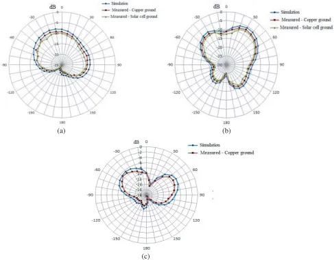
Figure 8. Gain radiation pattern of the proposed antenna for (a) 5.5 GHz, (b) 7.2 GHz, (c) 8.5 GHz.
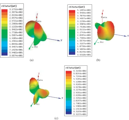
at 8.5 GHz are obtained, with 6.03 and 7.23 dBi directed at 60◦ and 6.64 and 7.84 dBi directed at 40◦, respectively. In summary, it can be seen that there is a good general agreement between simulated and measured results. There are a number of factors that account for a slight difference between the two sets of results, such as the fabrication tolerances of the antenna, calibration of the vector network analyzer, and possible multi-reflections in the measurement environment. Fig. 9 shows the 3D simulated radiation patterns for the frequencies 5.5, 7.2, and 8.5 GHz, respectively. The directivity is a function of patch width and dielectric constant. For the normal patch antenna with single substrate, the directivity is 6–8 dB. The simulated directivity radiation pattern of proposed antenna is shown in Fig. 10. The maximum directivity is obtained from the simulation results which is 0.153, equivalent to 8.12 dB. The probable air gap between the solar cell and antenna substrate in assembly shifts the resonant frequency of the antenna. The solar cell may increase the overall effective permittivity of the substrate for the antenna and accordingly lower the resonant frequency.
(a) (b)
(c)
Figure 9. 3D radiation pattern of the Stepped slot patch antenna with copper ground for (a) 5.5 GHz, (b) 7.2 GHz, (c) 8.5 GHz.
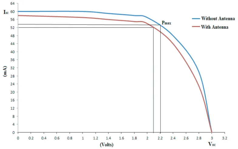
and current. The solar cell electrical characteristics, such as open-circuit voltage (VOC) and short-circuit current (ISC), are measured with and without integration of a stepped slot microstrip patch antenna as shown in Fig. 11. For the non-integrated antenna solar cell element, VOC and ISC values are measured to be VOC = 3 V and ISC= 60 mA. In contrast, when the stepped slot antenna element is placed above the solar cell, the observed output values are slightly decreased to VOC = 3 V and ISC = 58 mA. The rated output and VI characteristics of the solar cell with and without an antenna at different light
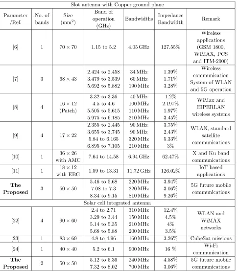
Table 1. Operating parameters of proposed antennas.
Antenna type Band of
operation (GHz)
Return
Loss (dB) VSWR
Impedance Bandwidth Stepped slot patch
antenna with copper ground plane
5.46–5.68 −24.25 1.12 3.94%
7.08–7.3 −20.47 1.2 3.06%
8.34–9.15 −34.06 1.03 9.26%
Stepped slot patch antenna with solar cell ground plane
5.12–5.36 −15.66 1.20 4.58%
Figure 10. Directivity radiation pattern. Figure 11. Solar cell DC characteristics measurement.
Figure 12. VI characteristics of solar cell with and without antenna.
[6] 1 70×70 1.15 to 5.2 4.05 GHz 127.55%
applications (GSM 1800, WiMAX, PCS and ITM-2000)
[7] 3 68×43
2.424 to 2.458 3.479 to 3.539 5.692 to 5.882
34 MHz 60 MHz 190 MHz 1.39% 1.71% 3.28% Wireless communication System of WLAN and 5G operation
[8] 4 16×12
(Patch)
3.32 to 3.36 4.5 to 4.6 5.505 to 5.615 5.975 to 6.185
40 MHz 100 MHz 110 MHz 210 MHz 1.2% 2.197% 1.97% 3.45% WiMax and HiPERLAN wireless systems
[9] 4 17×22
2.355 to 2.445 3.655 to 3.745 5.84 to 6.165 6.895 to 7.105
90 MHz 90 MHz 320 MHz 210 MHz 3.75% 2.43% 5.33% 3% WLAN, standard satellite communications
[10] 1 36×26
with AMC 7.64 to 14.58 6.94 GHz 62.47%
X and Ku band communications
[11] 1 18×12
with EBG 1.59 to 13.31 11.72 GHz 126.02%
IoT based applications
The
Proposed 3 50×50
5.46 to 5.68 7.08 to 7.3 8.34 to 9.15
220 MHz 220 MHz 810 MHz 3.94% 3.06% 9.26%
5G future mobile communications
Solar cell integrated antenna
[22] 4 90×60
2.4 to 2.71 3.29 to 3.44 5.14 to 5.35 5.68 to 5.88
310 MHz 150 MHz 210 MHz 200 MHz 12.4% 4.5% 4% 3.5% WLAN and WiMAX networks
[23] 1 83×69 4.8 to 4.96 160 MHz 3.26% CubeSat missions
[24] 1 40×40 5.2 to 6.1 900 MHz 16 % Wi-Fi
communication The
Proposed 2 50×50
5.12 to 5.36 7.32 to 8.02
240 MHz 700 MHz
4.58% 3.06%
performance, and also the solar ground plane acts as both a ground plane for radio communication and dc energy conversion.
4. CONCLUSION
In this paper, the design of a multi-band suspended stepped slot microstrip patch antenna with copper ground plane and solar cell ground plane has been proposed and demonstrated. The stepped slot patch antenna with copper ground plane covers the frequency bands ranging 5.46 GHz–5.68 GHz, 7.08 GHz– 7.3 GHz, and 8.34 GHz–9.15 GHz, and also the same radiating patch with solar ground plane covers the frequency bands ranging 5.12 GHz–5.36 GHz and 7.32 GHz–8.02 GHz. These new designs provide a building block for an integrated communication system for future mobile communications and also fulfill the need of dc generation. The proposed antenna system has several initiatives like data strategy, spectrum sharing for mobile and wireless data services, the quality and quantity of information on spectrum use which are relevant, or potentially relevant, to 5G and/or bands above 6 GHz.
ACKNOWLEDGMENT
The authors would like to thank Tamil Nadu State Council for Science and Technology (TNSCST) for sponsoring this work under short term Grants SPS 2016-2017.
REFERENCES
1. Yang, S.-L. S., A. A., Kishk, and K.-F. Lee, “Frequency reconfigurable U-slot microstrip patch antenna,” IEEE Antennas and Wireless Propagation Letters, Vol. 7, 127–129, 2008.
2. Bakariya, P. S., S. Dwari, M. Sarkar, and M. K. Mandal, “Proximity-coupled multiband microstrip antenna for wireless applications,”IEEE Antennas and Wireless Propagation Letters, Vol. 14, 755– 758, 2015.
3. Xu, K. D., Y. H. Zhang, R. Spiegel, Y. Fan, W. T. Joines, and Q. H. Liu, “Design of a stub-loaded ring-resonator slot for antenna applications,” IEEE Transactions on Antennas and Propagation, Vol. 63, No. 2, 517–524, 2015.
4. Mok, W. C., S. H. Wong, K. M. Luk, and K. F. Lee, “Single-layer single-patch dual-band and triple-band patch antennas,” IEEE Transactions on Antennas and Propagation, Vol. 61, No. 8, 4341–4344, 2013.
5. Khan, Q. U., D. Fazal, and M. bin Ihsan, “Use of slots to improve performance of patch in terms of gain and side lobes reduction,”IEEE Antennas and Wireless Propagation Letters, Vol. 14, 422–425, 2015.
6. Bhupendra, K., N. K. Shukla, and K. B. Rajendra,, “Wide slot antenna with Y shape tuning element for wireless applications,”Progress in Electromagnetics Research M, Vol. 59, 45–54, 2017. 7. Lu, H., Y. Liu, F. Liu, and W. Wang, “Single-feed single-patch triple-band single-beam/dual-beam
U-slotted patch antenna,”Progress In Electromagnetics Research M, Vol. 77, 17–28, 2019.
8. Das, S., P. P. Sarkar, and S. K. Chowdhury, “Modified π-shaped slot loaded multifrequency microstrip antenna,”Progress In Electromagnetics Research B, Vol. 64, 103–117, 2015.
9. Xue, W., M. Xiao, G. Sun, and F. Xu, “A compact low-profile and quad-band antenna with three different shaped slots,” Progress In Electromagnetics Research C, Vol. 70, 43–51, 2016.
10. Song, X. Y., T. L. Zhang, and Z. H. Yan, “Broadband and low-profile slot antenna with AMC surface for X/Ku applications,” Progress In Electromagnetics Research M, Vol. 71, 189–197, 2018. 11. Goswami, P. K. and G. Goswami, “Trident shape ultra-large band fractal slot EBG antenna for
multipurpose IoT applications,”Progress In Electromagnetics Research C, Vol. 96, 73–85, 2019. 12. Garg, R., P. Bhartia, I. Bahl, and A. Ittipiboon, Microstrip Antenna Design Handbook, Artech
House, Inc., 2001.
patch antenna on a-Si thin-film glass solar module,” Electronics Letters, Vol. 47, No. 2, 85–86, 2011.
20. Yurduseven, O. and D. Smith, “Solar cell stacked dual-polarized patch antenna for 5.8 GHz band WiMAX network,”Electronics Letters, Vol. 49, No. 24, 1514–1515, 2013.
21. Caso, R., A. D’Alessandro, A. Michel, and P. Nepa, “Integration of slot antennas in commercial photovoltaic panels for stand-alone communication systems,”IEEE Transactions on Antennas and Propagation, Vol. 61, No. 1, 62–69, 2013.
22. Yurduseven, O., D. Smith, N. Pearsall, and I. Forbes, “A solar cell stacked slot-loaded suspended microstrip patch antenna with multiband resonance characteristics for WLAN and Wi-MAX systems,”Progress In Electromagnetics Research, Vol. 142, 321–332, 2013.
23. Yekan, T. and R. Baktur, “An experimental study on the effect of commercial triple junction solar cells on patch antennas integrated on their cover glass,”Progress In Electromagnetics Research C, Vol. 63, 131–142, 2016.
24. Elsdon, M., O. Yurduseven, and X. Dai, “Wideband metamaterial solar cell antenna for 5 GHz Wi-Fi communication,”Progress In Electromagnetics Research C, Vol. 71, 123–131, 2017.
25. Al-Shalaby, N. A. and S. M. Gaber, “Parametric study on effect of solar-cell position on the performance of transparent DRA transmit array,” AEU-International Journal of Electronics and Communications, AEUE 51545, 1–6, 2016.