High Gain FSS Aperture Coupled Microstrip Patch Antenna
Niaz Muhammad1, *, Hassan Umair1, Zain Ul Islam1, 2, Zar Khitab1, Imran Rashid1, and Farooq A. Bhatti1
Abstract—This paper presents a high-gain cavity resonant antenna (CRA), consisting of an FSS layer placed above an aperture coupled microstrip patch antenna (ACMPA). Geometry of the proposed FSS superstrate is highly reflective with |Γ>0.9|. Ray-tracing method has been employed for determining the resonant condition of the antenna. ACMPA operating at S-band is serving as a feeding source. The coupling aperture of the antenna is of novel design, and several figures of merit have been presented for the proposed coupling aperture. Analysis of CRA has been carried out with the design parameters of the CRA. HFSS-13 has been utilized as simulation tool. Measured results are in good agreement with the simulated ones.
1. INTRODUCTION
Frequency selective surface (FSS) is a good candidate to be used as a superstrate over the antenna to increase its directivity and gain. The principle to achieve high directivity has been defined in [1] and is based on simple Ray-tracing phenomenon. It consists of multiple reflections taking place between the FSS layer and the ground plane of the source antenna. The waves in the process of multiple reflections are slightly leaked out of superstrate layer (FSS), otherwise the phenomenon is the same as in a Fabry-Perot resonator. Due to this resemblance these antennas are also known as Cavity Resonant antennas (CRA). Electromagnetic wave propagation can be controlled and manipulated by periodic structure called electromagnetic band-gap (EBG). High directive CRA is an application example of EBG antennas [2–4]. It is shown in the literature that cavity resonance based antennas have ability to enormously increase the directivity as compared to conventional antennas [5–7] and [9–13]. In these devices patch antenna, waveguide aperture or a dipole is used as a single feeding source and FSS is used as a superstrate above the feeding source at a distance ofλ/2 in [5–12] orλ/4, where the ground plane acts as the artificial magnetic conductor (AMC) [13]. In order to achieve high gain and wider input impedance, CRA with FSS-type superstrate is more beneficial than CRA with high permittivity type superstrates as the former is easy to fabricate and is of low cost [14].
For planar antenna configuration, aperture coupled microstrip patch antenna (ACMPA) has the advantages of low profile, low cost and ease of integration [15]. Gain and bandwidth are essential design parameters of a wireless communication system. However, these parameters are complimentary matrices, in that if one is improved, other is degraded. The study of gain bandwidth product (GBWP) with different slot shapes has been carried out in [16] and [17]. To obtain the desired performance out of the ACMPA, there are a number of structural geometries that need to be optimized. Among these, shape and size of coupling aperture is the most critical. The performance of various aperture types in terms of their GBWP is investigated in [16] and [17].
In this paper, a high directive CRA is presented. It consists of an FSS layer placed above ACMPA, here ACMPA serves as a feeding source. The coupling aperture in ACMPA is novel in design. Several
Received 21 February 2016, Accepted 25 April 2016, Scheduled 9 May 2016
* Corresponding author: Niaz Muhammad ([email protected]).
1 Department of Electrical Engineering, College of Signals, National University of Sciences & Technology (NUST), Islamabad,
figures of merit including GBWP are presented to validate the proposed coupling aperture. The designed FSS superstrate layer is composed of two dimensional periodic array of metallic patches. It is highly reflective with |Γ>0.9|. Parametric analysis over FSS geometry and its height from the ground plane has been carried out. Design frequency is 2.6 GHz. Simulated and measured results are given for validation. In Section 2 the complete design of the CRA and the ray tracing formulas are presented. Section 3 covers the GBWP and other figures of merit to assess the efficiency of the novel coupling aperture. Parametric study of the antenna is presented in Section 4. Final design and measured results are given in Section 5.
2. CRA DESIGN
CRA with ACMPA as a source antenna is shown in Figure 1(a). The ray tracing illustration of the process showing multiple reflections in a cavity and leaky waves outside the cavity through FSS layer is depicted in Figure 1(b) [14]. The complete design of ACMPA and FSS superstrate is discussed below.
(a) (b)
Figure 1. (a) Cavity resonance antenna (CRA) fed by aperture coupled antenna and (b) illustration of multiple reflections and leaky waves.
2.1. Aperture Coupled Microstrip Patch Antenna Design
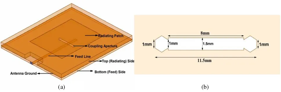
Aperture coupled microstrip patch antenna (ACMPA) as shown in Figure 2(a) is designed at operating frequency of 2.6 GHz. The antenna consists of two substrates, Taconic TLC (εr = 3.2, tanδ = 0.003)
(a) (b)
Figure 3. S11of ACMPA with different slot lengths.
(a) (b)
Figure 4. Simulated results of ACMPA, (a) S11 of the aperture coupled antenna and (b) gain of the
aperture coupled antenna.
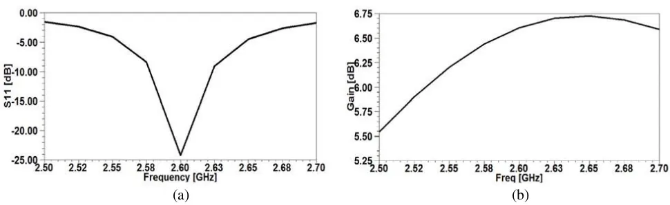
with 0.79 mm thickness and Rogers RT/Duroid 5880 (εr = 2.2, tanδ = 0.0009) with thickness of 1.575 mm. Both substrates have copper cladding of 35µm. Rogers has the radiating patch at the top and ground plane with a coupling aperture at the bottom. Taconic has the ground plane with coupling aperture at the top and feed-line at the bottom. The radiating rectangular patch with length and width of 35 mm and 28 mm respectively, is excited by the feed line through aperture/slot in the ground plane. The coupling aperture has a rectangular slot of length 8 mm and width 1.5 mm with augmented hexagonal slots at each end. The side length of hexagonal slot is 1 mm. The complete aperture is shown in Figure 2(b). The purpose of introducing rectangular slot with augmented hexagonal shaped slot is to introduce unique design and to perform the comparative analysis of the proposed aperture in terms of FOMs to establish its usefulness. By increasing the aperture size resonance resistance and coupling level increases. Resonant frequency is also very sensitive to the aperture length. By increasing the aperture length resonant frequency decreases. It is evident from Figure 3 that increase in length of the coupling aperture causes the resonant frequency to shift towards the lower frequency. The return loss and gain of the aperture coupled antenna is shown in Figure 4(a) and Figure 4(b) respectively. At 2.6 GHz, S11
is−24 dB and gain is 6.67 dB.
2.2. FSS Design
(a) (b)
Figure 5. (a) FSS array of metallic patches and (b) FSS unit cell.
(a) (b)
Figure 6. Reflection and transmission coefficients of FSS unit cell, (a) phase, (b) magnitude.
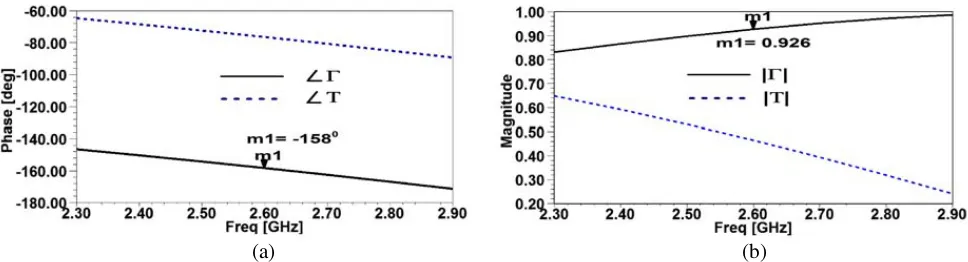
hexagonal elements at the four ends as a single entity in order to achieve the benefits of both the shapes. HFSS Floquet port analysis was used to design the unit cell. The phase of the FSS reflection and transmission coefficients is shown in Figure 6(a) and the magnitude of the FSS reflection and transmission coefficients is shown in Figure 6(b). The result shows that the FSS screen is highly reflective with reflection coefficient |Γ>0.9| and phase−158◦. To achieve high directivity, the superstrate and the radiating source need to be in resonant condition [8] and [18] and the resonance frequency of the reflecting layer (FSS superstrate) has to be in the frequency band of operation [20].
2.3. Resonance Estimation and Ray-tracing
The resonance condition for achieving the maximum power at the bore-sight for the antenna at an operating frequency “f” can be calculated as [21].
h= N λ
2 +
ψΓ(f) +ϕΓ(f)
π
λ
4 (1)
whereh is the height of the FSS superstrate layer from the ground plane, N the integer number equal to 1, and ϕΓ and ψΓ are the reflection phases of the ground plane and FSS, respectively. The value of
ψΓ from Figure 6(a) is−158◦ whereas the value of ϕΓ is calculated from the following equation:
ϕΓ ≈∠jZd
tan(βd)−Z0
jZdtan(βd) +Z0
=π−2 tan−1(Zdtan(βd)/Z0) (2)
turns out to be 179.88◦. Using the values of ϕΓ and ψΓ in Equation (1), resonant air gap turns out to
be 61.19 mm at resonant frequency of 2.6 GHz. For calculating the estimated directivity at bore-sight, an expression is derived in [1] and [6].
Dr =
1 +|ΓFSS|
1− |ΓFSS| (3)
The magnitude of the reflection coefficient of the FSS at 2.6 GHz is 0.92. The relative directivity is calculated to be 13.8 dBi. This means that if the directivity of the source antenna is from 6 dBi–7 dBi and we place this FSS layer with appropriate dimensions and at suitable height over the source antenna, we can achieve directivity as high as 19.8 dBi–20.8 dBi. The size of FSS used in this work is of 3×3 and 5×5 array of metallic patches. The simulated gain of the CRA with 3×3 FSS is 14.05 dB, and that of 5×5 is 15.67 dB. Much higher gain can be achieved by using greater size of the FSS, i.e., 7×7, 9×9. However, the constraint would be computational complexity. Besides, this also leads to a considerably large size of the antenna.
3. GAIN BANDWIDTH PRODUCT OF ACMPA AND CRA
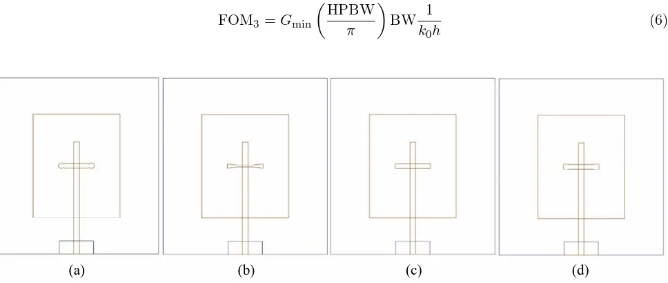
In this section, the performance of different shaped coupling apertures is analyzed for the designed antenna, with and without the FSS layer. ACMPA with different shaped coupling slots is shown in Figure 7. These aperture shapes include rectangular, hour-glass, H-shaped and proposed coupling aperture. Bandwidth and gain play significant role in defining the antenna performance and are key design characteristics that define the performance of a coupling aperture in case of aperture coupled antenna [16].
In order to define the efficiency of the proposed coupling aperture, some figures of merit (FOM) are calculated and comparatively studied. GBWP is one of them. It is established in [17] that the approximate formulae for the calculation of GBWP are used only for electrically thin substrates. GBWP is given as [17].
FOM1 = GBWP =GAVGBW (4)
where GAVG is the average linear gain. FOM2 in terms of the electrical height and minimum gain is
defined as [17].
FOM2 =GminBW
1 k0h
(5)
where Gmin is the minimum gain over the band and k0h the electrical height at central frequency fc. The FOM3 in terms of the HPBW is defined as [17].
FOM3 =Gmin
HPBW π
BW 1
k0h
(6)
(a) (b) (c) (d)
(a) (b)
Figure 8. Effect of ACMPA with different coupling apertures, (a) gain of ACMPA and (b) S11 of
ACMPA.
Table 1. FOMs of ACMPA with different shaped slot.
Antenna without FSS Gain BW HPBW/π k0h FOM1 FOM2 FOM3
This work 6.30–6.80 dB 0.050 0.444 0.059 0.227 3.771 1.674
H-shaped coupling
aperture antenna 6.42–6.67 dB 0.054 0.448 0.059 0.244 4.024 1.803
Hour-glass shaped
coupling aperture antenna 6.40–6.68 dB 0.044 0.453 0.059 0.198 3.251 1.473 Rectangular shaped
coupling aperture antenna 6.41–6.65 dB 0.046 0.455 0.059 0.206 3.411 1.552
Table 2. FOMs of CRA with different shaped slots.
Antenna with FSS Gain BW HPBW/π k0h FOM1 FOM2 FOM3
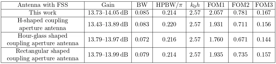
This work 13.73–14.05 dB 0.085 0.214 2.57 2.057 0.781 0.167
H-shaped coupling
aperture antenna 13.43–13.89 dB 0.083 0.220 2.57 1.931 0.711 0.156
Hour-glass shaped
coupling aperture antenna 13.79–13.97 dB 0.072 0.216 2.57 1.760 0.671 0.144 Rectangular shaped
coupling aperture antenna 13.79–13.99 dB 0.079 0.214 2.57 1.935 0.735 0.157
(a) (b)
Figure 9. Effect of different coupling apertures of CRA, (a) gain of CRA and (b)S11of CRA.
(a) (b)
Figure 10. Effect of FSS at different heights from the ground plane on (a) gain, (b)S11.
4. PARAMETRIC STUDY OF THE ANTENNA
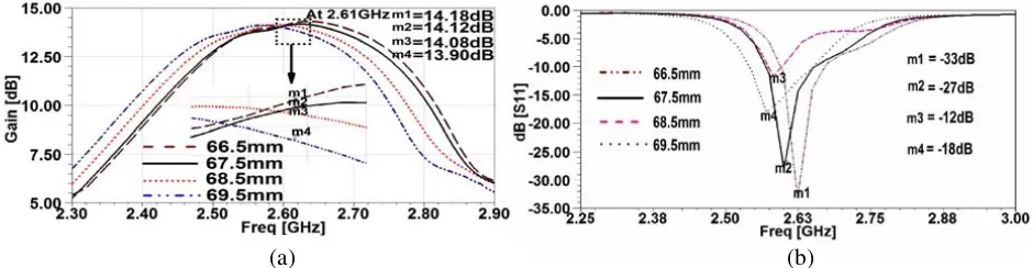
In this section, parametric analysis of the height and dimensions of FSS layer will be carried out. A full wave analysis of the designed CRA has been done by using FEM based (ANSOFT HFSS) software. It is established that the resonance frequency of the CRA antenna is affected by varying the distance between the ground plane of the antenna and the FSS superstrate layer. The large variations of height have more effect on the resonance condition than those of small variations. Therefore, in order to keep the antenna at resonance condition, for every height change some modifications in the design of the FSS are needed. To study the effect of FSS layer height on CRA, simulations at different heights have been carried out. Figure 10(a) illustrates the variation in gain by changing the height of the superstrate from the ground plane of the source antenna. Result shows that by decreasing the height, gain increases and shifts toward the higher frequencies. It is because of the fact that the magnitude of reflection coefficient of FSS increases with frequency. Therefore, high reflective superstrates have high gain capability. Figure 10(b) shows S11 for different heights of the FSS layer. Result shows that by
increasing the height of the superstrate, the resonance frequency of the CRA shifts toward the lower frequencies. Conversely, by decreasing the height, the resonance frequency increases. This is because of the well known effect that the FSS height and the resonant frequency are inversely related.
The dimension of the FSS is another very important parameter in designing CRA. Varying the array size shifts the resonance frequency. In order to make the antenna resonate at desired frequency, optimization in the design of the unit cell has to be carried out. The effect of increasing the array size of the FSS layer, also leads to the enhancement of the radiating aperture of the antenna. The deviation in S11 and gain for various FSS array sizes with respect to frequency is depicted in Figure 11(a) and
(a) (b)
Figure 11. Effect of FSS array size on (a) S11, (b) gain.
5. FINAL DESIGN AND MEASURED RESULTS
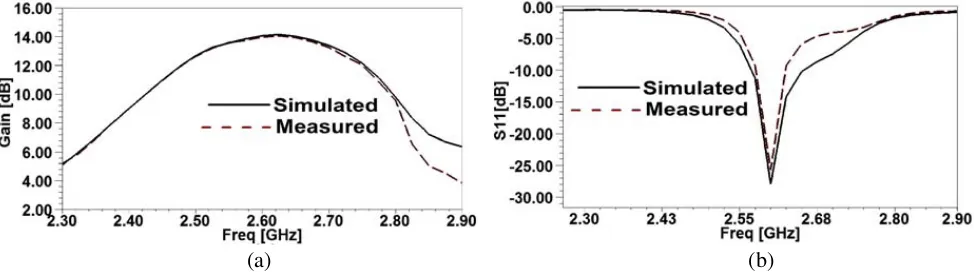
The fabricated antenna is shown in Figure 12. Figure 13(a) depicts the simulated vs measured gain. The simulated value of gain at 2.6 GHz is 14 dBi whereas measured value is 13.97 dBi. Return loss of the final optimized structure of the CRA is shown in Figure 13(b). The simulated value of S11 at
2.6 GHz is−27 dB whereas measured value is−24 dB. The bandwidth of the return loss (RL <−10 dB) for aperture coupled antenna from Figure 4(a) is 50 MHz (2.58–2.63) GHz and from Figure 13(b) the bandwidth of the CRA is 85 MHz (2.570–2.655) GHz. This shows that in comparison with aperture coupled antenna, percent bandwidth of the CRA has increased by 1.5%. The measured gain of the CRA antenna is about 13.97 dBi and that of the aperture coupled antenna is 6.67 dBi. This shows that the gain of the CRA antenna has increased by more than 100% due to the FSS superstrate layer.
(a) (b) (c) (d)
Figure 12. Fabricated antenna, (a) radiating ACMPA, (b) feed line, (c) coupling aperture in the ground plane and (d) CRA.
(a) (b)
(a) (b)
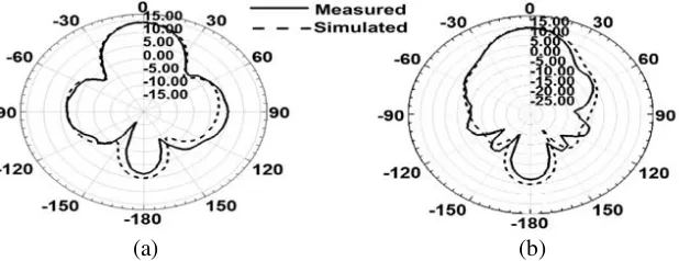
Figure 14. Measured and simulated radiation patterns of the 3×3 FSS CRA, (a) H-plane and (b) E-plane.
(a) (b)
Figure 15. Simulated radiation pattern of the 5×5 FSS CRA, (a)E-plane and (b) H-plane.
The final superstrate height from the ground plane of the source antenna is 67.5 mm. The periodicity of the patch type FSS elements is 10 mm. The width of the metallic patches of the FSS is 30 mm.
Simulated vs measured H-plane andE-plane gain plots of CRA with 3×3 FSS array at 2.6 GHz are depicted in Figure 14(a) and Figure 14(b), respectively. The HPBW of the E-plane gain plot is 38.5◦. The back lobes seen in the radiation patterns are due to aperture in the ground plane and can be reduced by using metallic reflector or an absorber material. A very good match can be observed in all simulated and measured results. The simulated gain plots at E-plane and H-plane of the 5×5 FSS array CRA are shown in Figure 15(a) and Figure 15(b) respectively. For 5×5 gain of 15.67 dB is achieved at the resonance frequency of 2.6 GHz. The HPBW of the E-plane gain plot is 33.2◦. To fix the frequency shift, 5×5 FSS dimensional parameters were not modified. The results in Figure 11 and Figure 15 show only the effect of FSS array size whereby increasing the overall array size of the FSS, resonant frequency shifts toward lower frequencies. In order to make CRA to resonate at 2.6 GHz the FSS dimensional parameters will need to be optimized.
6. CONCLUSION
employed with an array of patch (source) antennas. This will result in a much higher gain and can be explored further as a future work.
REFERENCES
1. Von Trentini, G., “Partially reflecting sheet arrays,” IRE Transactions on Antennas and Propagation, Vol. 4, No. 10, 666–671, 1956.
2. Boutayeb, H., K. Mahdjoubi, A. C. Tarot, and T. A. Denidni, “Directivity of an antenna embedded inside a Fabry-Perot cavity: Analysis and design,” Microwave and Optical Technology Letters, Vol. 48, No. 1, 12–17, 2006.
3. Weily, A. R., K. P. Esselle, B. C. Sanders, and T. S. Bird, “High-gain 1D EBG resonator antenna,”
Microwave and Optical Technology Letters, Vol. 47, No. 2, 107–114, 2005.
4. Lee, Y. J., J. Yeo, R. Mittra, and W. S. Park, “Application of electromagnetic band gap (EBG) superstrates with controllable defects for a class of patch antennas as spatial angular filters,”IEEE Transactions on Antennas and Propagation, Vol. 53, No. 1, 224–235, 2005.
5. Cheype, C., C. Serier, M. Thevenot, T. Monediere, A. Reineix, and B. Jecko, “An electromagnetic band gap resonator antenna,” IEEE Transactions on Antennas and Propagation, Vol. 50, No. 9, 1285–1290, 2002.
6. Feresidis, A. P. and J. C. Vardaxoglou, “High gain planar antenna using optimized partially reflective surfaces,” IEE Proceedings Microwave and Antennas Propagation, Vol. 148, No. 6, 345– 350, 2001.
7. Guerin, N., S. Enoch, G. Tayeb, P. Sabouroux, P. Vincent, and H. Legay, “A metallic Fabry-Perot directive antenna,”A Metallic Fabry-Perot Directive Antenna, Vol. 54, No. 1, 220–224, 2006. 8. Ge, Y. and K. P. Esselle, “A resonant cavity antenna based on an optimized thin superstrate,”
Microwave and Optical Technology Letters, Vol. 50, No. 12, 3057–3059, 2008.
9. Feresidis, A. P. and J. C. Vardaxoglou, “A broadband high-gain resonant cavity antenna with single feed,” Proceedings 1st EuCAP, 1–5, 2006.
10. Lee, D. H., Y. J. Lee, J. Yeo, R. Mittra, and W. S. Park, “Design of novel thin frequency selective surface superstrates for dual-band directivity enhancement,”IEEE Antennas and Wireless Propagation Letters, Vol. 1, No. 1, 248–254, 2007.
11. Moustafa, L. and B. Jecko, “EBG structure with wide defect band for broadband cavity antenna applications,” IEEE Antennas and Wireless Propagation Letters, Vol. 7, 693–696, 2008.
12. Ge, Y., K. P. Esselle, and T. S. Bird, “The use of simple thin partially reflective surfaces with positive reflection phase gradients to design wideband, low-profile EBG resonator antennas,”IEEE Transactions on Antennas and Propagation, Vol. 60, No. 2, 743–750, 2012.
13. Feresidis, A. P., G. Goussetis, S. Wang, and J. C. Vardaxoglou, “Artificial magnetic conductor surfaces and their application to low-profile high gain planar antennas,” IEEE Transactions on Antennas and Propagation, Vol. 53, No. 1, 209–215, 2005.
14. Foroozesh, A. and L. Shafai, “Investigation Into the effects of the patch-type FSS superstrate on the high-gain cavity resonance antenna design,”IEEE Transactions on Antennas and Propagation, Vol. 58, No. 2, 258–270, 2010.
15. Pozar, D. M., “Microstrip antenna aperture-coupled to a microstripline,” Electronics Letters, Vol. 21, No. 2, 49–50, 1985.
16. Bilgic, M. M. and K. Yegin, “Gain-bandwidth product for aperture-coupled antennas,” IEEE Computational Electromagnetic Workshop, 21–22, 2013.
17. Bilgic, M. M. and K. Yegin, “High gain wideband aperture coupled microstrip antenna design based on gain-bandwidth product analysis,” ACES Journal, Vol. 29, No. 8, 560–567, 2014.
18. Pirhadi, A., M. Hakkak, F. Keshmiri, and R. K. Baee, “Design of compact dual band high directive electromagnetic band gap (EBG) resonator antenna using artificial magnetic conductor,” IEEE Transactions on Antennas and Propagation., Vol. 55, No. 6, 1682–1690, 2007.
20. Pirhadi, A., H. Bahrami, and J. Nasri, “Wideband high directive aperture coupled microstrip antenna design by using a FSS superstrate layer,” IEEE Transactions on Antennas and Propagation, Vol. 60, No. 4, 2101–2104, 2012.