Scholarship@Western
Scholarship@Western
Electronic Thesis and Dissertation Repository
8-15-2019 10:30 AM
Pneumatic Hyperelastic Robotic End-Effector for Grasping Soft
Pneumatic Hyperelastic Robotic End-Effector for Grasping Soft
Curved Organic Objects
Curved Organic Objects
Alexandre Galley
The University of Western Ontario
Supervisor Knopf, George K.
The University of Western Ontario
Graduate Program in Mechanical and Materials Engineering
A thesis submitted in partial fulfillment of the requirements for the degree in Master of Engineering Science
© Alexandre Galley 2019
Follow this and additional works at: https://ir.lib.uwo.ca/etd Part of the Other Mechanical Engineering Commons
Recommended Citation Recommended Citation
Galley, Alexandre, "Pneumatic Hyperelastic Robotic End-Effector for Grasping Soft Curved Organic Objects" (2019). Electronic Thesis and Dissertation Repository. 6392.
https://ir.lib.uwo.ca/etd/6392
This Dissertation/Thesis is brought to you for free and open access by Scholarship@Western. It has been accepted for inclusion in Electronic Thesis and Dissertation Repository by an authorized administrator of
ii
Abstract
Pneumatically-driven soft robotic grippers can elastically deform to grasp delicate, curved organic objects with minimal surface damage. However, common actuators have multipart geometries and are fabricated with ultra-soft hyperelastic elastomers not originally intended for scientific applications. The complexity of the actuator geometry and extreme nonlinearity of their material’s stress-strain behaviour make it difficult to predict the actuator’s deformation prior to experimentation. In this work, a compact soft pneumatic gripper made with polydimethylsiloxane (PDMS) is developed for grasping delicate organic objects, analyzed through computational modelling and experimentally validated. COMSOL Multiphysics is used to simulate the impact of geometrical parameters on the actuator’s behaviour, allowing for the refinement of the proposed geometry prior to fabrication. Optimal parameters are selected for fabrication, with experimental tests matching simulations within ± 1.11 mm. Gripper performance is evaluated for three actuator wall thicknesses in terms of contact area with target, contact force, and maximum payload before slippage. The comparative assessment between simulations and experiments demonstrate that the proposed soft actuators can be used in robotic grippers tailored for grasping delicate objects without damaging their surface. Furthermore, analysis of the actuators provides additional insight on how to design simple but effective soft systems.
Keywords
iii
iv
Acknowledgments
This research is the result of collaboration between the University of Western Ontario (London, Ontario) and Vineland Research and Innovation Centre, Lincoln, Ontario, Canada. This research was funded, in part, by a Mitacs Accelerate Internship grant and Natural Sciences and Engineering Research Council of Canada (NSERC) Discovery Grant (Number: RGPIN/05858-2014.). Specifically, I would like to thank Drs. Gideon Avigad and Mohamed Kashkoush from Vineland Research for their support and guidance during the early stages of this research project.
Special thanks to my supervisor Prof. George K. Knopf for his continual support, advice, and encouragement. I appreciate the opportunity he gave me to work in such a complex and interesting field. I would also like to thank Dr. Dogan Sinar, who gave me advice on how to approach my work and how to get started with PDMS. The dedication you both show to your work is inspiring.
My appreciation also goes out to Prof. Aaron Price and the members of the Organic Mechatronics and Smart Materials Laboratory, especially Andrew Cullen, Ben Holness, and Rami Abu-Shammeh, for their insight, support, and friendship throughout my studies. Allowing me the use of their lab space proved critical to my work. I would also like to extend my thanks and gratitude to laboratory supervisor Mr. Dave Lunn, both for his friendship and for helping me throughout my studies and TA duties. Thank you to my colleague Mr. Ahmed Tanashi for his help and use of his TrakSTAR sensor system. I can very honestly say that I could not have done it without them.
v
Abstract ... ii
Summary for Lay Audience ... iii
Acknowledgments ... iv
List of Figures ... viii
List of Tables ... xiv
List of Appendices ... xv
List of Abbreviations, Terminology and Nomenclature ... xvi
1 Introduction ... 1
1.1 Research Motivation ... 2
1.2 Objectives of Research ... 3
1.3 Major Contributions ... 4
1.4 Thesis Organization ... 5
2 Background and Literature Review ... 6
2.1 Hyperelastic Theory ... 6
2.1.1 Governing Equations ... 7
2.2 Polydimethylsiloxane (PDMS) ... 11
2.2.1 Ultra-soft, Unpredictable Elastomers ... 11
2.2.2 Properties of PDMS ... 12
2.2.3 Importance of Degassing PDMS ... 14
2.2.4 Removing PDMS from a Mould ... 15
2.2.5 Partial Moulding Techniques ... 16
2.3 Soft Robotics Technology... 16
2.3.1 Review of Soft Pneumatic Actuators ... 17
vi
3 Design Methodology and Fabrication ... 33
3.1 Geometric Design of Elastomeric Actuators ... 33
3.2 Actuator Fabrication ... 35
3.3 Role and Functionality of COMSOL Multiphysics Software ... 40
3.3.1 Defining PDMS Material Properties for Finite Element Modelling ... 40
3.3.2 Model Implementation in COMSOL Multiphysics 5.3 ... 42
3.3.3 Mesh Generation for Finite Element Modelling ... 43
3.4 Chapter Summary ... 44
4 COMSOL Simulations and Results ... 45
4.1 Wall Displacement for a Parameter Change ... 45
4.2 Surface Loads ... 49
4.3 Relating to the Strain-Energy Function ... 50
4.4 Principal Strain and Principal Stretch ... 54
4.5 Chapter Summary ... 58
5 Experimental Setup and Testing ... 59
5.1 Actuator Displacement Under Applied Pressure ... 59
5.1.1 Experimental Setup ... 60
5.1.2 Measured Actuator Displacement ... 61
5.1.3 Wall Displacement over Pressure ... 62
5.2 Gripper Contact Forces and Maximum Payload Capabilities ... 63
5.2.1 Experimental Setup ... 63
5.2.2 Contact Force and Maximum Payload Results ... 65
5.3 Chapter Summary ... 66
6 Application Study and Discussion ... 67
6.1 Robotic Harvesting Systems in Horticulture ... 67
vii
6.2 Parameters for Evaluation ... 71
6.3 Application Testing ... 72
6.4 Discussion of Results ... 75
6.5 Design for Different Applications ... 79
6.6 Chapter Summary ... 80
7 Concluding Remarks ... 81
7.1 Summary of Thesis ... 81
7.2 Summary of Conclusions ... 83
7.3 Recommendations for Future Research ... 84
Bibliography ... 86
A PneuNet Actuators ... 92
B Vacuum Cups ... 96
C Supporting Information on Mushrooms ... 99
C.1 The White Mushroom, Agaricus Bisporus ... 99
C.2 Graze Harvesting Strategy ... 101
C.3 Overview of Existing Infrastructure at Vineland Research and Innovation Centre Inc. . 101
C.4 Mushroom Sample Measurements ... 103
D Actuator Moulding System CAD & Drawings ... 107
E Copyright Permissions ... 114
viii
List of Figures
Figure 2.1 Stress-strain curve during a loading cycle. (a) Elastomer hyperelastic material behaviour; (b) Linear elastic material behaviour. Note that the Young’s moduli are not to scale. As described by
[24], [26], [27]. ...7
Figure 2.2 Volume element subjected to (a) uniaxial stress (σ) and (b) principal stresses. ...7
Figure 2.3 Empirical formula of PDMS. As shown on Sigma-Aldrich [39]. ...12
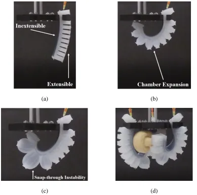
Figure 2.4 Pneumatic Network soft bending actuators. (a) Deflated state; (b) Inflated State; (c)
Ultra-soft material instability; (d) Limitations as a gripper design for the research application. Note that the
actuators shown in this figure were fabricated as part of preliminary work for this research thesis. ...18
Figure 2.5 Fiber-Reinforced actuators at different sleeve spacing configurations (Galloway et al. [63]
© 2013 IEEE, included with permission). ...21
Figure 2.6 FR actuator fabrication (Galloway). (a) Mould components; (b) Multi-step fabrication
process (Galloway et al. [63] © 2013 IEEE, included with permission). ...23
Figure 2.7 FR actuator fabrication (Miron) (Miron et al. [33] © 2018 CC-BY, included with
permission). ...24
Figure 2.8 Pneumatic artificial muscles. (a) PAM contraction for increasing pressure with constant
mass; (b) Enhanced view of PAM braided sleeve. Figures created at Western University. ...25
Figure 2.9 McKibben EBPAM. (a) Modified extensor McKibben actuator; (b) Extensor McKibben
actuator further modified to bend (Al-Fahaam et al. [66], © 2018 Elsevier, included with permission).
...26
Figure 2.10 Early Whitesides PneuNet grippers. Grasping an egg (top) and a sedated mouse (bottom)
(Whitesides et al. [6], © 2011 WILEY, included with permission)...28
Figure 2.11 PneuNet Gripper for delicate ocean reef sampling (Galloway et al. [70], © 2016 Mary
Ann Liebert, Inc., included with permission). ...29
Figure 2.12 Universal PneuNet gripper testing tunable actuator lengths (Hao et al. [58], © 2016
ix
Figure 2.14 Small (left) and large (right) variants of the Fiber Reinforced gripper developed at
Sherbrooke University (Miron et al. [33], © 2018 CC-BY, included with permission). ...31
Figure 3.1 (a) Bottom view of a gripper comprised of three soft pneumatic actuators. (b) Outside geometry of the actuator’s pneumatic chamber. (c) Internal structure of the chamber walls, location of
the strain-limiting fiber mesh (blue) and the impact of inflation δd on the active deformable wall
(red). Note that the deformation is for visualization purposes only. ...34
Figure 3.2 Top view of the (a) base for Mould 1; (b) base for Mould 2; and (c) detachable outer
walls. ...36
Figure 3.3 Key steps in the fabrication actuator fabrication process. (a) Assembly of outer walls on
the base for Mould 1; (b) Pour PDMS pre-polymer in mould cavity; (c) Extract PDMS part from
disassembled mould; (d) Fill bottom of base cavity of Mould 2 with partially cured PDMS and then
uncured pre-polymer; (e) Align and secure PDMS part on partially cured layer; and (f) disassemble
mould to remove completed actuator with a single air inlet through-hole to chamber. ...38
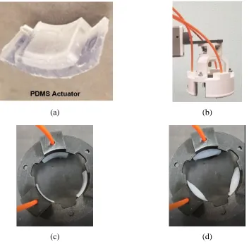
Figure 3.4 (a) Single moulded PDMS actuator; (b) Robotic end-effector with the elastomeric
actuators inserted into the gripper assembly (coloured white); Top view of gripper ring in (c) deflated
state and (d) moderate inflated state. For the sake of picture clarity, the actuators shown in (c) and (d)
of this figure were fabricated out of Ecoflex 00-30. Ecoflex is white while PDMS is nearly
transparent. ...39
Figure 3.5 Material data for PDMS from COMSOL Multiphysics’ Material Library Module. ...41
Figure 3.6 Wireframe of single actuator. (a) Fixed constraint highlighted in yellow; (b) Boundary
load to concave deformable wall highlighted in blue; (c) Finite element mesh generated over model
geometry and locally refined at concave deformable wall surface. ...42
Figure 4.1 (a) Simulated model showing wall displacement due to expansion; (b) top view of
simulated model of single actuator with expansion of the principle active wall. ...46
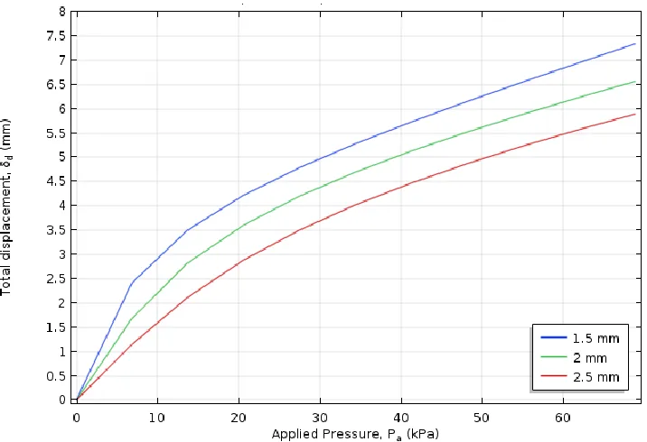
Figure 4.2 Simulated displacement (δd) values for three expandable wall thicknesses (td) at Pa =
x
Figure 4.4 Displacement (δd) as a function of both (a) actuator height (h) and (b) arc angle (α) for
td = 2 mm and Pa= 6.89 kPa. ...49
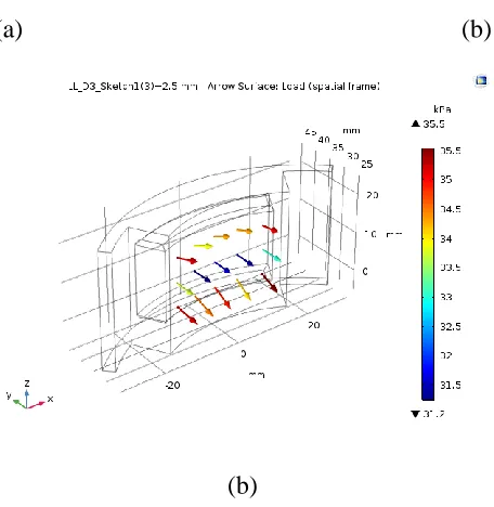
Figure 4.5 Simulated surface loads (Pc) with an applied pressure of 34.37 kPa. (a) td= 1.5 mm; (b) td= 2 mm; (c) td= 2.5 mm ...50
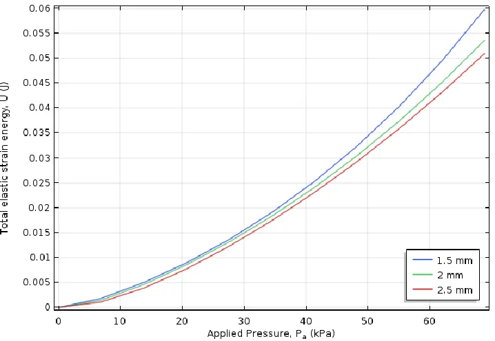
Figure 4.6 Simulated total elastic strain-energy (U) at different pressures (Pa, kPa). ...51
Figure 4.7 Simulated stored energy density (W) at different pressures (Pa, kPa). ...52
Figure 4.8 Simulated volumetric strain energy density (Wv) at different pressures (Pa, kPa). ...53
Figure 4.9 Simulated isochoric strain energy density (Wiso) at different pressures (Pa, kPa). ...53
Figure 4.10 Principal strain directions under applied pressures (Pa, kPa). (a) 0 kPa; (b) 68.94 kPa. ..54
Figure 4.11 Principal strains (ϵi) under applied pressure (Pa, kPa) for an actuator wall thickness of td = 1.5 mm. ...55
Figure 4.12 Principal stretches (λi) under applied pressure (Pa, kPa) for an actuator wall thickness of td = 1.5 mm. ...55
Figure 4.13 Principal stretches (λi) over time for an actuator wall thickness of td = 1.5 mm. ...56
Figure 4.14 Principal stretches (λi) over time for an actuator wall thickness of td = 2 mm. ...57
Figure 4.15 Principal stretches (λi) over time for an actuator wall thickness of td = 2.5 mm. ...57
Figure 5.1 Experimental setup and test procedure. (a) Testing of a single actuator with a positioning sensor; (b) Sensor data for displacement testing of a single actuator. The dips in the figure show three separate instances of displacement for one test. Note that this the test shown in this figure is performed over a period of 20 seconds. The time period is reduced to 10 seconds after the TrakSTAR system underwent initial calibration. ...61
xi
Figure 5.4 Setup for contact force tests. Top view of painted gripper ring in (a) deflated and (b)
inflated states; (c) 3D model of contact area on sphere. ...64
Figure 5.5 Experimental setup for payload tests. (a) Close-up of spherical target held in gripper; (b)
sphere target for payload test; and (c) cylindrical target for payload test. ...65
Figure 6.1 Commercially-available vacuum cups provided by Vineland. (a) Bellows-type cup; (b)
Bell-type cup. ...71
Figure 6.2 Experimental setup and manual test procedure. (a) Gripper placed over mushroom; (b)
Gripper lifting mushroom from threaded rod; (c) Organic test object (i.e., mushroom) embedded on
threaded rod. ...72
Figure 6.3 Results of grasp-and-hold experiments (success/failure) and observed damage to
mushroom surfaces during the tests (damaged/undamaged). These results are for tests with the
vacuum cups. ...73
Figure 6.4 Observed damage on mushroom cap inflicted by vacuum cup. (a) Indented ring of
damage; (b) Inflicted damage outlined with red circle; (c) Bell-type cup geometry collapsing under
vacuum pressure...74
Figure 6.5 Results of grasp-and-hold experiments (success/failure) and observed damage to
mushroom surfaces during the tests (damaged/undamaged). These results are for tests with the soft
PDMS gripper variants. ...75
Figure A.1 PneuNet Actuator. (a) At rest; (b) Full Actuation; (c) Observed Instability due to
ultra-soft hyperelastic Ecoflex 00-30. ...93
Figure A.2 PneuNet Gripper. (a) At rest; (b) and (c) show two separate instances of snap-through
instability. ...94
Figure A.3 Grasping attempt with 4 cm diameter foam sphere. (a) Positioning the sphere between the
PneuNet actuators; (b) PneuNet gripper failing to properly hold 4 cm diameter foam sphere by its
fingertips. ...94
xii
by its fingertips. ...95
Figure A.6 PneuNet gripper attempting to grasp a soft foam mushroom. (a) Initially succeeding but
(b) eventually failing to grasp by its fingertips. ...95
Figure B.1 Sketch of vacuum cup operating principle. ...96
Figure B.2 Vacuum cup geometries tested. (a) Bellows-type cup; (b) Bell-type cup; (c) Cup Iteration
1; (d) Cup Iteration 2; (e) Cup Iteration 3. ...97
Figure B.3 Results of grasp-and-hold experiments (success/failure) and observed damage to
mushroom surfaces during the tests (damaged/undamaged). These results are for tests with all
vacuum cups. ...98
Figure C.1 Basic anatomy of a mushroom (Leeuwen et al. [77], © 1999 Elsevier, included with
permission). ...99
Figure C.2 Development stages of Agaricus Bisporus in terms of growth (Hammond et al. [79], ©
1976 Journal of General Microbiology, included with permission). ...100
Figure C.3 Kinematic diagram of PreciseFlex robotic manipulator in use at the Vineland facility.
Adapted from PreciseFlex reference manual [80]. ...102
Figure C.4 Operating principle of Venturi vacuum ejector. (A) Ejector inlet; (B) Venturi nozzle; (C)
Sound-reducing silencer; (D) Vacuum connection. As described by the SCHMALZ webpage [82]. 103
Figure C.5 Mushroom sample measurements. (a) Cross-section dimensions; (b) Mass measurements
with Mettler Toledo digital scale. ...105
Figure C.6 Mushroom population for sample measurements (sample size n = 8). ...106
Figure D.1 CAD of actuator mould assemblies. (a) Mould set for actuator body; (b) Mould set for
actuator bottom. Both models shown have the closest wall, nuts, and bolts hidden to provide a view of
the mould interior. ...108
Figure E.1 Copyright permission statement by IEEE Publisher. ...116
xiii
Figure E.4 Copyright permission information for confirmation number 11824398. ...119
Figure E.5 Copyright permission information for confirmation number 4611460433957. ...120
Figure E.6 Copyright permission information for confirmation number 11824409. ...121
xiv
List of Tables
Table 2.1 Properties of PDMS, Sylgard 184, summarized from [39]. ...13
Table 2.2 Performance summary of actuator designs. ...27
Table 2.3 Performance summary of gripper designs. ...32
Table 3.1 Key design parameters used to analyze soft pneumatic actuators during operation. ...35
Table 5.1 Contact force and payload test results for all gripper geometries. Test object is a foam sphere unless stated otherwise in brackets. ...66
Table 6.1 Standard performance indicators for robotic harvesting systems...68
Table 6.2 Comparison of test results for Vacuum Cup and PDMS Soft Gripper performance with reported performance indicators in literature. ...77
Table 6.3 Summary of design guidelines. ...79
Table C.1 Development stages of Agaricus Bisporus in terms of mushroom cap diameter ranges. Adapted from [74]...100
Table C.2 Summary of mushroom sample measurements. ...105
xv
A PneuNet Actuators ... 92
B Vacuum Cups ... 96
C Supporting Information on Mushrooms ... 99
D Actuator Moulding System CAD & Drawings ... 107
xvi
List of Abbreviations, Terminology and
Nomenclature
Abbreviations
3D Three-Dimensional
ABS Acrylonitrile Butadiene Styrene CAD Computer-Aided Design
DOF Degree-of-Freedom
EBPAM Extensor Bending Pneumatic Artificial Muscle FEA Finite Element Analysis
FR Fiber-Reinforced
NSERC Natural Sciences and Engineering Research Council PAM Pneumatic Artificial Muscle
PDE Partial Differential Equation PDMS Polydimethylsiloxane PneuNet Pneumatic Network
Terminology
COMSOL Multiphysics
xvii
A constitutive model establishes a close approximation of a material’s real behaviour.
Direct farm cash receipt
A direct farm cash receipt represents the cash income received from the sale of agricultural merchandise and direct program subsidy payments.
Green deformation tensor
The Green deformation tensor is a measurement of large displacements and deformations as strain in material coordinates.
Gripper
A gripper is a type of end-effector or tool end on robotic manipulator systems. Situated at the end of the manipulator arm, the gripper’s purpose is to grasp a target object.
Hooke’s law
Hooke’s law states that, for linear materials, the strain in a solid is proportional to the applied stress within that solid’s elastic limit.
Hyperelastic material
A hyperelastic material is capable of large deformations under small loads. It is not characterized by Hooke’s law.
Inert
An inert material has properties that make it chemically inactive.
Mooney-Rivlin
xviii
A principal strain has a maximized normal vector.
Principal stretch
A principal stretch has a maximized normal vector.
Soft lithography
Soft lithography is a classification of techniques for fabricating or replicating elastomeric structures that includes stamps, open, and closed cavity moulding.
Soft robotics
The field of soft robotics covers robotic systems that implement inherent or material compliance.
Surfactant
A surfactant is a chemical solution that reduces adhesion between mould surfaces and pre-polymer mixtures by reducing surface tension of a fluid.
Thermosetting
A thermosetting material has properties that are permanently set when heated.
Venturi principle
The Venturi principle is the reduction in fluid pressure resulting when a fluid flows through a constricted pipe section.
Viscoelastic
xix 𝐴𝑐 Contact area
𝐶𝑖𝑖 Material constants
𝐹𝑏𝑢𝑜𝑦𝑎𝑛𝑐𝑦 Buoyancy force
𝐹𝑐 Contact force
𝐼𝑖 Principal strain invariant (i = 1, 2, 3, …)
𝐾1 Bulk modulus
𝑃𝑎 Applied pressure
𝑃𝑐 Contact pressure
𝑉𝑏 Volume of submerged body
𝑊𝑖𝑠𝑜(𝑓) Isochoric term, strain-energy density
𝑊𝑣(𝑓) Volumetric term, strain-energy density
𝑙𝑜 Original length
𝑚𝐿 Slip test payload mass
𝑡𝑑 Thickness of deformable wall
𝑡𝑟 Thickness of rear wall
𝛿𝑑 Displacement at center of actuator wall
𝜆𝑖 Principal stretch ratio, (i = 1, 2, 3, …)
xx 𝜖𝑖 Principal strain (i = 1, 2, 3, …)
°C Degrees Celsius °F Degrees Fahrenheit
ℎ Actuator chamber height
𝐴 Area
𝐸 Young’s Modulus
𝐹 Force
𝐽 Elastic volume ratio
𝑈 Strain-energy
𝑊 Strain-energy density
𝑑 Actuator chamber depth
𝑔 Gravity
𝑙 Final length
𝛥𝐴 Change in cross-sectional area
𝛥𝐹 Difference in force
𝛥𝑈 Difference in strain-energy
𝛥𝑉 Difference in volume
xxi 𝜈 Poisson’s Ratio
𝜎 Uniaxial stress
Chapter 1
Introduction
Soft robotics can be defined as the research field covering robotic systems that interact with their environment by relying on inherent or structural compliance [1]. Soft-material robotics is a specific branch of this field that studies inherent material compliance, and how deformation of a soft material can be controlled to achieve robotic functionality. A common feature of soft materials, whether they be liquids, gels, polymers, etc., is that they consist of large molecules or assemblies of molecules that move collectively. As a result, they provide a large, slow and nonlinear response to small forces [1]. Most research on soft-material robotics focuses on materials with a low Young’s modulus (< 1 GPa) at ambient temperature [1], [2].
2
very nonlinear stress-strain properties, making it difficult to predict the actuator’s behaviour. In many cases, the elastomeric materials used are commercially branded as special effects rubber for prosthetics in the performing arts, and thus the material data is rarely outlined. As a consequence of the inherent nonlinearity and lack of available material properties, most soft robotic grippers must be developed through an iterative design process based on trial-and-error experiments.
1.1 Research Motivation
There is an economic incentive to improving the design process of soft robotic grippers for horticultural product harvesting. A 2017 symposium report published by Vineland Research and Innovation Centre Inc. states that there are over 27,500 horticulture farms in Canada, covering approximately 1 million acres of land and producing $5 billion in annual direct farm cash receipts [8]. In the 5 years prior to the report, Ontario had accounted for nearly 60% of Canadian horticulture sales each year [8]. Labour costs take a significant toll on the horticulture sector, being as high as 40-50% of the cost of goods [8], [9]. In addition, a diminishing labour pool is recognizable in as early as 2014 when the industry was unable to fill 5,800 employment positions. This cost the industry over $350 million, with 60% of field-fruit and vegetable farms reporting sales losses. The shortage is projected to increase by 2025, and it is expected that 32-45% of the horticulture sector’s labour demands will not be met by domestic workers [8].
3
Mushrooms have a very delicate body that can be easily damaged by conventional gripper designs. They do not grow in neat, orderly lines. Instead, they spread across large growing beds, packed together by the thousands. Conventional rigid end-effectors are ill-suited for the manipulation of delicate organic objects in such a dense environment, as they are likely to damage both the collected target and mushrooms growing adjacent to it.
Prior attempts have been made to eliminate the rigid end-effector by employing robotic vacuum end-effectors [12]–[14], [16]–[22]. In theory, a non-rigid suction cup with a soft sealing base can deform around a mushroom cap’s irregular geometry and pull it from its growing bed. This method has proven only partially successful, as gripping forces applied to the cap surface can still be excessive due to the limited contact area of the suction cup. Conventional cups have a fixed open diameter which require accurate positioning over the cap. Misalignment can lead to further damage. Optimizing the conventional suction cup designs are not likely to fully eliminate damage inflicted to the mushroom due to the high variability in mushroom size, orientation, and cluster density.
1.2 Objectives of Research
4
In collaboration with the Vineland Research and Innovation Centre Inc., this research also aims to investigate the validity of these actuators in a proposed soft gripper design by comparing their performance to both commercial and custom vacuum cup geometries for automated mushroom harvesting. The target fungi in question is Agaricus Bisporus, more commonly known as the white mushroom. Although literature exists on numerous attempts at designing and optimizing systems and methods for automated mushroom harvesting, little is found on the implementation of soft robotics in this field. Thus, the secondary objective is to investigate the proposed soft gripper design’s viability for this application. By comparing the gripper design to both standard and modified vacuum cup geometries, the validity of the proposed design can be evaluated. In addition, modifying existing cup geometries proves that attempting to optimize vacuum cup systems will not fully resolve the issues related to mushroom harvesting.
1.3 Major Contributions
This thesis provides the following major contributions to the scientific community: • Starting foundation for hybrid computational/experimental design of soft robotic
grippers and actuators. A comparative method of assessing the performance of soft robotic actuators made of hyperelastic materials. This has been achieved through the classification of key parameters for analysis and comparing the impact of changing these parameters using nonlinear simulation software and experiments. This reduces the number of iterations required to be fabricated throughout the design process.
• Pneumatically-driven soft robotic gripper for automated mushroom harvesting.
5
• Established summary of design guidelines for soft robotic grippers. A summarized set of design guidelines for adapting the proposed gripper structure for various applications. These guidelines provide instruction on which parameters to modify to redesign the soft compliant end-effector for grasping different targets.
1.4 Thesis Organization
Chapter 2
Background and Literature Review
This chapter first provides an introduction to hyperelastic material theory. It also provides relevant background information on soft robotics technology, with a focus on air-driven soft material actuators and grippers. Additional background on the intended application, mushroom harvesting, is presented in this thesis. However, the goal of this chapter is to provide the necessary information fundamental to understanding soft robots and their functionality. Robotic harvesters in horticulture are presented at the beginning of Chapter 6. All additional information related to mushrooms is available in Appendix C.
2.1 Hyperelastic Theory
7
large deformations, taking into account intrinsic (relating to the material microstructure) and geometric (relating to the material’s shape) nonlinearities [28], [29].
(a) (b)
Figure 2.1 Stress-strain curve during a loading cycle. (a) Elastomer hyperelastic material behaviour; (b) Linear elastic material behaviour. Note that the Young’s moduli are not to scale. As described by [24], [26], [27].
2.1.1 Governing Equations
A material tends to store energy internally throughout its volume as it is deformed by an external load. This internal energy is related to material strain and is known as the strain-energy. Consider an object under tension, where a volume element of the object is subjected to a uniaxial stress (Figure 2.2a) [30].
(a) (b)
8
This stress in turn develops a force on the top and bottom faces of the element once it undergoes a displacement. The difference in these forces is defined by
∆𝐹 = 𝜎∆𝐴 = 𝜎(Δ𝑥Δ𝑦) (2.1) where (𝜎) is the uniaxial stress and (∆𝐴) is the change in cross-sectional area of the element normal to the stress, after the element of length Δ𝑧 undergoes a vertical displacement. Work is defined by the product of the force and related displacement. Since force is uniformly increased from zero to its final magnitude when this displacement is reached, the work done by the force on the element is equal to the product of the average force magnitude and the displacement. With the assumption of no energy loss, the external work becomes equal to the internal energy, also known as the strain-energy stored in the element. Therefore, the strain-energy can be defined by
∆𝑈 = (∆𝐹
2 ) 𝜖∆𝑧 = 1
2𝜎∆𝐴𝜖∆𝑧 (2.2)
∆𝑈 =1
2𝜎𝜖∆𝑉 (2.3)
where (𝜖) is the strain and (𝜖∆𝑧) is the material element’s vertical displacement. Equation (2.3) can be rewritten to formulate the strain-energy per unit volume of material. This is known as the strain-energy density.
𝑊 = ∆𝑈 ∆𝑉 =
1
2𝜎𝜖 (2.4)
Now consider this same volume element, now subject to three principal stresses (Figure 2.2b). Equation (2.4) can be rewritten such that each principal stress contributes a portion of the total strain-energy density.
𝑊 =1
2𝜎1𝜖1+ 1
2𝜎2𝜖2+ 1
2𝜎3𝜖3 (2.5)
9
elastic modulus is not sufficient for characterizing their behaviour when dealing with large deformations. A constitutive model is required for simulating the true behaviour of the hyperelastic material and associated structures at high strains [23], [25], [27], [28]. A suitable constitutive model can be derived from a strain-energy density function (𝑊) that represents the energy stored in the material per unit volume of the original geometry as a function of strain at that point in the material. Mathematically, this relationship is defined as [23]
𝑊 = 𝑓(𝐼1, 𝐼2, 𝐼3) = 𝑓((𝜆12+ 𝜆22+ 𝜆23), (𝜆12𝜆22+ 𝜆22𝜆32+ 𝜆32𝜆12), (𝜆12𝜆22𝜆32)) (2.6)
where 𝐼1, 𝐼2, and 𝐼3 are the three strain invariants of the Green deformation tensor. The individual strain invariants are a function of the principal stretch ratios (𝜆𝑖, 𝑖 = 1, 2 and 3).
The stretch ratio is a measure of the extensional strain that is normal to a material line element. It can be defined within either the natural or deformed state as the ratio between the final and initial lengths of the material line. In other words,
𝜆 = 𝑙 𝑙0 =
𝑙 − 𝑙0+ 𝑙0
𝑙0 = 𝜖 + 1 (2.7)
where 𝑙 is the final length, 𝑙0 is the original length, and 𝜖 is the material strain. Stretch
invariants are the properties by which the hyperelastic model can have a non-zero solution. The third invariant term given by equation (2.6) is related to the elastic volume ratio (𝐽) by 𝐼3 = 𝐽2. Introducing the volume ratio term enables a more convenient constitutive
model to be developed for nearly incompressible materials where
𝐼̅1 = 𝐼1
𝐽2 3⁄ and 𝐼̅2 =
𝐼2
𝐽4 3⁄ (2.8)
10
change in shape and is known as the volumetric term, 𝑊𝑣(𝑓). The strain-energy density can therefore be given as
𝑊 = 𝑊𝑖𝑠𝑜(𝐼̅1, 𝐼̅2) + 𝑊𝑣(𝐽) (2.9) where 𝐽 = √𝐼3. By assuming an incompressible material, 𝐽 = 1.
In this study, the Mooney-Rivlin model [23], [25], [27] is used to simulate the hyperelastic behaviour of the PDMS material used in the pneumatically-driven soft actuators. The generalized form of strain-energy density is given by
𝑊 =𝜇1
2 (𝐼̅1− 3) + 𝜇2
2 (𝐼̅2− 3) + 𝐾1
2 (𝐽 − 1)
2 (2.10)
where 𝜇 and 𝐾1 are the shear and bulk moduli of the solid, respectively. In this case, 𝜇1 =
𝐶10 = 7
16𝜇 and 𝜇2 = 𝐶01 = 1
16𝜇. Correspondingly, the shear modulus is 𝜇 = 2(𝐶10+
𝐶01). The material constants 𝐶10 and 𝐶01 are set as such to fulfill the approximation for rubber-like materials of 𝐶10= 7𝐶01 [27], [31], [32].
11
2.2 Polydimethylsiloxane (PDMS)
2.2.1 Ultra-soft, Unpredictable Elastomers
Pneumatically-driven soft actuators have been fabricated from a variety of commercially available silicone elastomers like Ecoflex™, DragonSkin™ and pre-made tubes of commercial silicone [33]. Although these elastomeric materials are ultra-soft and can be moulded into single and multi-chambered actuators, they were developed for non-scientific applications like theatrical prosthetics and, therefore, very little information is available about their underlying engineering properties. Furthermore, these ultra-soft materials exhibit inconsistent hyperelastic behaviour under pressurization making it very difficult to analyze fabricated chambers either through simulation or controlled repeatable experiments.
Ultra-soft elastomers are susceptible to modes of instability such as snap-through buckling, a bi-stable form of nonlinear buckling common in ultra-soft elastomers and thin-walled geometries [34], [35]. At high air pressure inputs, the elastomeric chambers undergo large deformations at an accelerated and unstable rate. The actuator chamber walls are more susceptible to buckling under these conditions, where the displacement under load will “snap-through”. When this occurs, the actuator’s chambers will exhibit a sudden and significant change in geometry before stabilizing at a new configuration [36]. Removing the pressure causes the chamber geometry to revert to its original stable form, or “snap-back”.
12
2.2.2 Properties of PDMS
PDMS is a mineral-organic polymer, with a structure that contains both carbon and silicon, from the siloxane family (silicon, oxygen, alkane) [25]. The brand used in this research, Sylgard 184, is available as a fluid monomer base and curing agent. To fabricate solid PDMS, the liquid base is mixed with the cross-linking agent and then poured into a mould to create the desired geometry. The empirical formula (Figure 2.3) of PDMS is
(𝐶2𝐻6𝑂𝑆𝑖)𝑛, and the fragmented formula is 𝐶𝐻3[𝑆𝑖(𝐶𝐻3)2𝑂]𝑛𝑆𝑖(𝐶𝐻3)3, where 𝑛 is the
number of monomer repetitions in the polymer chain [25].
Figure 2.3 Empirical formula of PDMS. As shown on Sigma-Aldrich [39].
13
reduction is attributed to thermal decomposition, which starts at 200 °C and reaches a peak at 310 °C. Work by McDonald and Whitesides [43] summarizes the material properties of Sylgard 184 PDMS, shown in Table 2.1.
Table 2.1 Properties of PDMS, Sylgard 184, summarized from [43].
Property Characteristic Consequence
Mechanical Elastomeric; tunable Young’s Modulus
𝐸 = 0.75 𝑀𝑃𝑎 – 4 𝑀𝑃𝑎
Conforms to surface; allows actuation by reversible deformation; facilitates release
from moulds
Thermal
Insulating; thermal conductivity,
0.2 𝑊(𝑚 · 𝐾); coefficient of thermal expansion, 310 𝜇𝑚/(𝑚 · °𝐶)
Can be used to insulate heated solutions; does not allow dissipation of resistive heating from electrophoretic separation
Interfacial
Low surface free energy
~ 20 𝑒𝑟𝑔/𝑐𝑚2
Replicas release easily from the mould; can be reversible sealed with materials
Permeability Impermeable to liquid water; permeable
to gases and nonpolar organic solvents
Contains aqueous solutions in channels; allows gas transport through the bulk material; incompatible with many organic
solvents
14
2.2.3 Importance of Degassing PDMS
Uncured PDMS is in the form of a thick liquid with a viscosity of approximately 3.5 kg/m·s [39]. This means that the fluid is susceptible to trapped gas bubbles before curing. Sylgard-184 PDMS is sold as a kit containing a monomer base and curing agent and mixing these two compounds together creates many air bubbles. Once the PDMS is cured, any bubbles that haven’t dissipated will remain trapped in the solid geometry, creating points of weakness in the actuator structure. Even worse, an air bubble that creates a hole through any of the actuator walls renders the whole geometry useless. Therefore, it is critical that all gas bubbles be completely removed before the PDMS can cure.
Techniques exist to improve the removal of gas bubbles from the uncured PDMS mixture by increasing the buoyant forces that the viscous liquid exerts upon them. The buoyancy force acting in the opposite direction of gravity, 𝑔, of a submerged body [46] is given by
𝐹𝑏𝑢𝑜𝑦𝑎𝑛𝑐𝑦 = 𝜌𝑓𝑉𝑏𝑔 (2.11)
where 𝜌𝑓 is the density of the fluid and 𝑉𝑏 is the submerged body’s volume. Vacuum degassing is the most common method of degassing PDMS. It is used in microfluidics [37], [38], as well as existing soft robotic [47], [48] literature where open cavity moulds are placed in a vacuum chamber. The mixed and heavily-aerated PDMS then becomes subject to negative pressure. The trapped air bubbles, previously at atmospheric pressure, now expand in volume. This also increases the exerted buoyant force in equation (2.11). Degassing with a vacuum chamber may require a long time to fully remove all bubbles depending on the initial number of bubbles present, the vertical distance they must rise to reach the surface, and wall friction effects.
15
multi-step moulding techniques described in Chapter 3 of this work, multiple degassing sessions are therefore necessary.
2.2.4 Removing PDMS from a Mould
Chapter 3 will present the multi-step moulding techniques used to fabricate the soft PDMS actuators. Extracting the part from the mould is a crucial and delicate process to preserve the overall quality of the demoulded geometry. For soft actuators, any defects, cuts or tears due to careless or improper removal techniques greatly diminishes, if not fully ruins, the functionality of the device. As mentioned in Table 2.1, the elastomeric properties of PDMS make fabricated geometries easy to peel off a complex master pattern. However, this is assuming that there is little-to-no adhesion between the PDMS and mould surface. Soft pneumatic actuators require much larger moulds compared to conventional microfluidics work, resulting in greater contact between the PDMS and multiple complex surface geometries. If enough adhesion between the mould surfaces and the PDMS part exists, actuator features may bond to the mould surface and tear when removal is attempted. Unwanted adhesion may result in high strains on the PDMS geometry during removal, which may cause permanent deformation.
16
structure warping, depending on the combined polymer and silane agent. Silanes can also be hazardous and costly. Chang-Yen et al. [52] proposes a safer and more cost-effective solution by replacing the silane agent with an industrial cleaning solution. The work found that a detergent-based agent on SU-8 patterns performed with greater success than silane agents.
2.2.5 Partial Moulding Techniques
The multi-step fabrication technique mentions partially curing the PDMS in some steps, where the PDMS is cured for only half the required time. In this case, the PDMS has only just solidified and its surface still contains bondable polymer chains. More uncured PDMS can be poured over this surface, and this will bond with the surface’s available polymer chains. Work by Eddings et al. [53] states that partial curing showed the highest bond strength compared to any other bonding technique.
2.3 Soft Robotics Technology
Research on soft-material robotic grippers using soft elastomers can be dated back to the late 1980s and early 1990s [1]. One of the first pieces of published work for a continuously-deforming elastomeric geometry is by Wilson and Mahajan in 1989 [54]. They present a pneumatically-driven arm made of soft elastomeric bellows. The attached grippers are made of additional bellows to create a soft robotic assembly. The actuation and bending of these bellows allowed the arm to perform pick-and-place operations of irregularly shaped objects [1], [54]. Other pieces of critical work include research by Suzumori et al. [55], [56]. In this research, the bellows-like actuators are replaced with novel tri-cellular units. The three cells are distributed about a central axis, each spanning 120°. The precise configuration of these units could be implemented in gripper designs and hexapod walkers for object manipulation and soft robotic locomotion [1], [55], [56].
17
improvement of new technologies. Interest in the field has rekindled in the early 21st
century since the establishment of soft materials as a field of material science research in the early 1990s. Many new soft materials have been created and made available on a commercial scale. The development of diverse fabrication techniques for soft materials, and the level of accessibility of these techniques, has increased. An increase is also noted in the magnitude of the research and work, published in high-profile journals, that demonstrate the use of soft materials in robotic applications. Overall, it is generally agreed in the relevant scientific community that soft robotic technologies can and should be used in future robotic applications where they would provide a naturally cheaper, safer, and more adaptive solution for intricate applications in unstructured environments as opposed to conventional rigid systems [57].
2.3.1 Review of Soft Pneumatic Actuators
Also known as Fluidic Elastomer Actuators, soft pneumatic actuators are one of the most common and widespread soft robotic design. During operation, the applied pressurized air causes the inflation and deformation of one or more inner chambers (i.e., cavities). These actuators are typically fabricated from ultra-soft and highly deformable materials including synthetic rubbers or silicone polymers and elastomers [3], [5]. Soft lithography techniques and the integration of soft composite materials (i.e., embedded strain-limiting membranes) are combined to fabricate the soft actuator structure and predict its motion [2]. Predicting actuator behaviour is further improved with design asymmetry and the careful selection of constituent materials.
2.3.1.1 Pneumatic Networks
18
expand and press against each other. This creates a difference in strain between the extensible and inextensible layers, resulting in a directional bending motion (Figure 2.4). The PneuNet actuator is meant to approximate the behaviour of a biological finger. Each additional inflating chamber within the PneuNet corresponds to an additional bending DOF. With the use of ultra-soft elastomers, the actuator can have an infinite number of DOF [58]. The principle behind the PneuNet’s bending motion has been implemented in a number of applications including multigait movement [5], medical rehabilitation devices [59], and the manipulation of various objects [58].
(a) (b)
(c) (d)
19
The most recent PneuNet design by Mosadegh et al. [4], of which a custom fabrication is shown in Figure 2.4, investigates the impact of reducing the expansion volume of the structure by adding gaps between the chambers. Less material between the chambers allow the chamber walls to expand preferentially under pressure, reducing the deformation and strain on portions of the structure not critical for bending. The study shows that reducing the expansion volume increases the speed at which the actuator bends (the actuation speed) and reduces the operating pressure for full actuation. The reduced deformation and operating pressure in turn reduce the material strain, significantly improving the actuator’s durable life. However, these improvements come at the reduction of applicable tip forces. The lower operating pressures reduce the actuator’s contact forces, consequently diminishing the structure’s payload capabilities as a gripper. The work also studied the impact of using different materials. The original design is fabricated with Ecoflex 00-30 and PDMS as the extensible and inextensible layers, respectively. Replacing the soft Ecoflex with a stiffer elastomer (Elastosil M4601) showed that while stiffer material geometries required significantly more pressure to fully actuate (approximately 8X more), a smaller change in volume is needed (approximately 1.5X less) to bend completely. It was also shown that the greater expansion volume required with softer material geometries is a direct consequence of the additional and extraneous expansion of non-critical actuator sections (i.e., walls not used in the bending motion). This means that actuators fabricated from a softer elastomer have a reduced actuation speed and apply lower tip forces for a given inflation pressure as compared to the same structure made with a stiffer material [4]. Performance parameters for the PneuNet design are established by Mosadegh et al. [4]. They are:
1. Speed achieved for a given rate of inflation. 2. Force exerted for a given pressure.
3. Change in volume required for a given degree of bending. 4. Number of actuation cycles before failure.
20
Two major limitations are present in Mosadegh et al.’s design. The length and size of the PneuNet structure, combined with the lack of material between the inflating chamber walls, cause the actuator to bend slightly under gravity. In addition, the actuator’s chambers may not expand simultaneously and uniformly when pressurized above a certain threshold (200 kPa). This is due to snap-through instability, as mentioned in Section 2.2.1.
Soft Robotics Toolkit, the website created for educational purposes by the Harvard Biodesign Lab, provides several methods of fabricating soft robotic sensors and actuators [60]–[62], including a simple method of creating a basic PneuNet actuator. As previously explained, the PneuNet actuators are composed of two parts; the top extensible body containing the chambers that deform when the actuator is pressurized, and a bottom inextensible layer containing a strip of strain-limiting material. These two parts are fabricated separately in specific mould geometries before being bonded together. The webpage discusses fabrication of the PneuNet with Ecoflex 00-30 as the hyperelastic material, a strip of paper as the strain-limiting layer and suggests using an oven to accelerate the curing process. The work by Mosadegh et al [4] elaborates on the fabrication process for the most recent PneuNet design in a supporting document [7]. Moulds are made of acrylonitrile butadiene styrene (ABS) polymer with a three-dimensional (3D) printer. Three mould parts are used: interior and exterior pieces for the top body, and a flat rectangular mould for the inextensible bottom. The flaw with this method lies in the strain-limiting material used. Paper strips are prone to tearing and can break down when submerged in a fluid (i.e., the elastomer mixture). A more durable strain-limiting material is therefore required. Some preliminary work is performed on the fabrication of a PneuNet design. It is presented in Appendix A.
2.3.1.2 Fiber-Reinforced Actuators
21
the strain-limiting layer preventing the flat surface of the actuator from stretching, the geometry will perform a bending motion. The fibrous material can include, but is not limited to, Kevlar thread, nylon, and string [33], [63], [64]. Contact points between the soft actuator membrane and the reinforcing fibers create sources of highly localized strains and abrasion, which are both known causes of actuator failure by rupture [33]. To reduce these strains, a sleeve cover can be placed over the fiber strands.
Figure 2.5 Fiber-Reinforced actuators at different sleeve spacing configurations (Galloway et al. [63] © 2013 IEEE, included with permission).
22
configuration exhibits the lowest radius of curvature for a given pressure. This suggests that the rigid laminate sheets can localize actuation to the sleeve spacing, an important concept for the purposes of this research thesis as it shows that incorporating passive rigid elements into a soft actuator assembly can improve control over the system [63].
Comparing the two elastomers used shows that the softer material (DragonSkin 10) exhibited the highest sensitivity to a given pressure with respect to bending deflection [63]. In all cases and configurations, the softer elastomer can achieve smaller radii of curvature. However, the softer material is also more susceptible to instabilities at high pressures (over 400 kPa) and becomes highly prone to failure by rupture. Like the work by Mosadegh et al. on the PneuNet [4], this suggests that while a softer material structure may initially produce forces comparable to a stiffer elastomer, the stiffer material can support higher pressures. Thus, it can also produce larger forces. In summary, the described research presents trade-offs in actuator performance between sensitivity of deformation to air pressure, output force, and radius of curvature for a FR actuator.
23
(a) (b)
Figure 2.6 FR actuator fabrication (Galloway). (a) Mould components; (b) Multi-step fabrication process (Galloway et al. [63] © 2013 IEEE, included with permission).
Another study by Miron et al. [33] in Sherbrooke, QC, presents a similar design. Though the design is primarily tested as a gripper system (and thus will be discussed in Section 2.3.2), the proposed design presents an emphasis on three fatigue principles for FR actuators. These are:
1. Reduction in local stresses and strains.
2. Reduction in surface damage from abrasion and fiber-on-membrane cutting. 3. Operating below a material’s fatigue limit; the strain under which the fatigue life
tends towards infinity.
24
Figure 2.7 FR actuator fabrication (Miron) (Miron et al. [33] © 2018 CC-BY, included with permission).
2.3.1.3 Pneumatic Artificial Muscles
25
(a) (b)
Figure 2.8 Pneumatic artificial muscles. (a) PAM contraction for increasing pressure with constant mass; (b) Enhanced view of PAM braided sleeve. Figures created at Western University.
26
(a)
(b)
Figure 2.9 McKibben EBPAM. (a) Modified extensor McKibben actuator; (b) Extensor McKibben actuator further modified to bend (Al-Fahaam et al. [66], © 2018 Elsevier, included with permission).
27
Table 2.2 Performance summary of actuator designs.
Actuator Material Mass Operating Pressure
Actuation Speed
Applied
Force Comments Reference
PneuNet EcoFlex 00-30 (extensible); PDMS (inextensible); Paper (strain-limiting layer)
- 72 kPa 130
milliseconds 1.4 N - [4]
FR Actuator
DragonSkin
10 - 172 kPa - 2.75 N
30 mm sleeve spacing
[63] Elastosil
M4601 - 414 kPa - 7.12 N
30 mm sleeve spacing
McKibben PAM
- 50 g 300 kPa -
650 N (rest); 300N (15%); 0 N (30%) 150 mm rest length, 14 mm diameter [65]
- 32 g 300 kPa -
220 N (rest); 100 N (10%); 0 N (20%) 150 mm rest length McKibben
EBPAM - - 500 kPa - 42 N
bending
actuator [66]
Soft robotic designs exist for end-effectors or manipulators that implement PAM actuators in object manipulation applications [68], [69]. These systems typically emulate the complex biological behaviour of elephant trunks or cephalopod tentacles, the nature of which is not suited for the purposes of this research thesis.
2.3.2 Review of Soft Pneumatic Grippers
28
gripper distributes the target’s load over the gripper’s entire surface instead of a few force points.
Figure 2.10 Early Whitesides PneuNet grippers. Grasping an egg (top) and a sedated mouse (bottom) (Whitesides et al. [6], © 2011 WILEY, included with permission).
29
Figure 2.11 PneuNet Gripper for delicate ocean reef sampling (Galloway et al. [70], © 2016 Mary Ann Liebert, Inc., included with permission).
30
Figure 2.12 Universal PneuNet gripper testing tunable actuator lengths (Hao et al. [58], © 2016 IEEE, included with permission).
Soft Robotics Inc., a company based in Cambridge, MA, produces and sells basic PneuNet grippers for industrial pick-and-place operations. Though information on their design is proprietary, application videos on their website show an alleged maximum payload of 4.5 kg [33].
2.3.2.1 Fiber-Reinforced Grippers
31
Figure 2.13 Maximum payload test of Fiber Reinforced grippers with different actuator sleeve spacing configurations (Galloway et al. [63], © 2013 IEEE, included with permission).
Using a similar FR actuator design, Miron et al. [33] developed two gripper assemblies: one small and one large. Both grippers are assembled by fixing the actuators to a 3D printed polymer plate. By configuring the actuators around the plate, the gripper can be organized as “fingers” on a “palm” [33]. The smaller gripper has three actuators in a 2-1 facing configuration, while the larger gripper can hold four actuators in a 2-2 offset configuration. However, the study performed its experiments with a large gripper having a 2-1 configuration to allow comparison between the two designs (Figure 2.14).
32
A summary of the performance of several gripper designs, including operating pressures and applicable forces and payloads, is available in Table 2.3.
Table 2.3 Performance summary of gripper designs.
Gripper Material Mass Operating Pressure Contact Force Contact Pressure Slip
Tests Payload Comments Reference
PneuNet Gripper Elastosil M4601 core; Smooth-Sil 950 exterior - 68.9 kPa
- 2 kPa -
2 kg
-
[70]
With foam insert
- 7 kPa - -
124 kPa - - 16.6 N Vertical
5.6 N Horizontal
DragonSkin
30 50 kPa - - 13.5 N -
Maximum value for all
trials
[58]
- - - 4.5 kg SoftRobotics
Inc. [33]
FR Actuator
Gripper
Elastosil
M4601 90 g 345 kPa - - -
3.45 kg No sleeve cover
[63] 4.68 kg 0 mm sleeve
spacing
6.1 kg
0 mm sleeve spacing; FR Laminate
sheets
- 112.6 g
275 kPa 20 N - - 52 N Small [33]
- 594 g 28 N - - 200 N Large
2.4 Chapter Summary
Chapter 3
Design Methodology and
Fabrication
This chapter outlines the design and fabrication of a pneumatically-driven soft robotic gripper. The geometric design for the soft actuator and gripper is proposed. Fabrication of the gripper actuators is outlined in detail, involving a multi-step moulding process. The role and functionality of the computational software, COMSOL Multiphysics, is presented.
3.1 Geometric Design of Elastomeric Actuators
34
A soft pneumatic gripper comprised of three compact PDMS actuators (Figure 3.1a) is developed for grasping irregular shaped organic objects such as mushroom tops, strawberries, and small citrus fruits during automated harvesting [10]. Each constituent actuator has a curved geometry (Figure 3.1b) and operates similarly to a single chamber PneuNet [2] with only one deformable concave wall that expands toward the center of the gripper assembly during pressurization (Figure 3.1c). Therefore, unlike bending actuator-based grippers that use a combination of interlocking actuator fingers and friction forces to grasp a target, the proposed design holds the target through friction forces alone. The modular single-DOF actuator was designed for functional simplicity, ease of fabrication and assembly, reliability, and repeatable performance. In addition, the design enabled a realistic model of the stress behaviour to be simulated using COMSOL Multiphysics software. The simulations were necessary to predict the impact of key design parameters on the gripper’s performance during air inflation.
(a) (b) (c)
Figure 3.1 (a) Bottom view of a gripper comprised of three soft pneumatic actuators. (b) Outside geometry of the actuator’s pneumatic chamber. (c) Internal structure of the chamber walls, location of the strain-limiting fiber mesh (blue) and the impact of inflation
(𝛿𝑑) on the active deformable wall (red). Note that the deformation is for visualization
purposes only.
35
inner wall (𝑡𝑑). The majority of chamber expansion will occur along the inner concave wall and, therefore, it is labeled the actuator’s primary active deformable wall. When inflated with pressurized air the freely moving expandable primary wall produces a center displacement (𝛿𝑑) with a predictable contact pressure (𝑃𝑐). The displacement and contact pressure are dependent upon both the actuator’s chamber geometry and the applied air pressure input (𝑃𝑎). The geometric parameters used to simulate and experimentally assess
the performance of the proposed hyperelastic actuator are given in Table 3.1. Furthermore, the impact of these parameters will be evaluated over a range of low applied air pressures
(𝑃𝑎).
Table 3.1 Key design parameters used to analyze soft pneumatic actuators during operation.
Parameter Range of Values
Wall thickness, 𝑡𝑑 1.5 mm, 2 mm, 2.5 mm
Actuator chamber height, ℎ 10 - 30 mm; increments of 2 mm Actuator arc angle, 𝛼 45°− 90°; increments of 5°
Applied air pressure, 𝑃𝑎 6.89Pa – 68.9 kPa (1psi - 10 psi)
3.2 Actuator Fabrication
Section 3.3 introduces the model setup in COMSOL Multiphysics for simulations that are described in Chapter 4. However, to keep the design and fabrication of the actuators together, Section 3.2 first describes the moulding process used to create the actuator prototypes. These actuators are validated through experiments presented in Chapter 5. The process described in Section 3.2 is general to all actuator prototypes fabricated. Note that the actuators are fabricated for testing after the simulations are completed.
36
has been bypassed by using only 3D printed ABS polymers for the mould components and by embedding the strain-limiting layer at the end of the whole process. Elastomers are acquired as pre-polymer mixtures to be prepared and poured into the moulds, avoiding the limitations imposed by purchasing pre-made silicone structures. This fabrication methodology provides complete control over every aspect of the soft PDMS actuator including geometry and material properties. The hyperelastic actuators are fabricated using a multistep soft lithography moulding process. The method requires two circular mould bases (Mould 1 and Mould 2) and a detachable outer wall as shown in Figure 3.2, where each reusable mould assembly can produce up to three compact pneumatic actuators at a time. Mould 1 is used to form the majority of the part geometry with a single open exposed surface while Mould 2 creates the final surface used to close the pneumatic chamber for the actuators. The moulds are designed for proper alignment during assembly and a combination of partial curing and adhesive bonding for assembling the discrete PDMS components. Before coming into contact with any PDMS pre-polymer, every surface of the mould assemblies is coated with a layer of surfactant. A mixture of soft detergent and water is used to prevent the pre-polymer from adhering to the 3D printed mould components.
(a) (b) (c)
Figure 3.2 Top view of the (a) base for Mould 1; (b) base for Mould 2; and (c) detachable outer walls.
37
38
Figure 3.3 Key steps in the fabrication actuator fabrication process. (a) Assembly of outer walls on the base for Mould 1; (b) Pour PDMS pre-polymer in mould cavity; (c) Extract PDMS part from disassembled mould; (d) Fill bottom of base cavity of Mould 2 with partially cured PDMS and then uncured pre-polymer; (e) Align and secure PDMS part on partially cured layer; and (f) disassemble mould to remove completed actuator with a single air inlet through-hole to chamber.
The PDMS pre-polymer is first degassed as soon as it is mixed until no air bubbles are observable. It is then slowly poured into the open moulds in small increments at a time. Once the moulds are filled, they are placed into the vacuum chamber and degassed again. Every step that involves the agitation of the PDMS pre-polymer is followed by another degassing session. This is to ensure that there are no bubbles in the mixture.
39
Once fabricated, three identical actuators (Figure 3.4a) are inserted into the 3D printed housing unit to form the circular ring-like gripper (3.4c and 3.4d). The rigid ring has inlets that allow polyurethane tubing to connect to the actuators. A coupling extension connects the gripper ring to a manipulator arm (3.4b). It also adds clearance between the arm and the gripper ring. All rigid structural components of the gripper housing unit and robot attachment are made of ABS polymer. The ring structure can hold the actuators of varying chamber heights and arc angles, but all experiments focus on the deformable inner concave wall thicknesses. The ABS ring weighs approximately 34 g, and each actuator weighs approximately 14 g. In total, each gripper weighs approximately 76 g.
(a) (b)
(c) (d)
40
3.3 Role and Functionality of COMSOL Multiphysics Software
COMSOL Multiphysics is an extensive, multi-functional finite element analysis (FEA) solver and simulation software package. Starting as a base program, additional software modules can be added to solve specific multiphysics problems. For this research, the Structural Mechanics Module was used with the Nonlinear Structural Materials Module for the analysis of hyperelastic geometries under static loads. The Material Library Module is used to implement material properties related to PDMS (10:1 mixing ratio, cured at 25°C). The CAD Import Module and LiveLink for SolidWorks add-on are used to synchronize the generated SolidWorks models with COMSOL simulations.
COMSOL Multiphysics provides a reliable and efficient method of analysis. Based on the simulations, the deformation of a particular actuator geometry can be calculated and used to quantify performance. This is advantageous to the process of soft robotic design, as it permits numeric comparison of various design geometries, identification of sources of strain, and a benchmark for assessing acceptability of performance.
Performing simulations introduces the benefit of being able to assess the impact of numerous geometrical parameters on the actuator’s performance at a significantly accelerated rate relative to fabricating physical iterations. By selecting a single geometrical parameter at a time, COMSOL can solve for a swept range of parameter values and provide quantitative results for each. These simulations can be performed in time-independent (stationary) and time-dependent conditions. In addition, COMSOL includes a detailed data-solving system with which a single simulation can provide a multitude of different results including displacements, stresses, strains, and contact forces generated by pressure loads. These results can be viewed in one, two, or three dimensions.
![Figure 2.3 Empirical formula of PDMS. As shown on Sigma-Aldrich [39].](https://thumb-us.123doks.com/thumbv2/123dok_us/1895675.1247924/33.612.257.393.270.372/figure-empirical-formula-pdms-shown-sigma-aldrich.webp)
![Table 2.1 Properties of PDMS, Sylgard 184, summarized from [43].](https://thumb-us.123doks.com/thumbv2/123dok_us/1895675.1247924/34.612.110.544.159.366/table-properties-pdms-sylgard-summarized.webp)
![Figure 2.12 Universal PneuNet gripper testing tunable actuator lengths (Hao et al. [58], ©](https://thumb-us.123doks.com/thumbv2/123dok_us/1895675.1247924/51.612.245.401.76.267/figure-universal-pneunet-gripper-testing-tunable-actuator-lengths.webp)