A BSTRACT: A low complexity an d erro r to leran t d esign has more demand in th e s ig n al p ro ces s in g s ystems. Parallel-prefix adders (also known as carry tree adders) are known to have the best performan ce in VLSI d es ig n s . Ho wev er, th is p erfo rman ce ad vantage does no t tran s late d irectly in to FPGA imp lementations due to constrain ts o n lo g ic b lo ck co nfigurations and routing overhead . FFTs are th e key building blocks in man y co mmu n icatio n an d s ignal processing systems. An efficient conflict -free ad dress scheme for arbitrary point memory-based fast Fo u rier transform (FFT) p ro ces s o r u s in g p arallel p refix add er was exh ib ited in th is p ap er. In th e p roposed scheme,the inputs are given along with th e twiddle factor and we g et th e o u tp u ts as fas t as p o ssible because of parallel prefix adders. Due to th e p resence of a fas t carry -ch ain , th e PPA d es ig n s exh ib it better delay p erfo rman ce. Th e carry -tree ad ders are expected to have a speed advantag e o v er th e RCA.The efficien t co mp u ta tio n o f Dis crete Fo u rier Transform (DFT) is an important issue as it is u s ed in almost all fields o f en g in eerin g fo r s ig n al p ro cessing. This paper presents a d ifferen t fo rm o f Rad ix-2 Fast Fo u rier Tran s fo rm (FFT) b as ed o n Decimatio n in time (DIT) to co mp u t e DFT.
Index terms: Fas t Fo u rier Tran s fo rms (FFTs ), Dis creteFourierTransform(DFT),FieldProgrammable Gate A rray (FPGA ).
1. INTRODUCTION
In Communication and Signal processing systems the complexity of the circuits increases. This is made feasible by the scaling of CMOS technology. Scaling means the transistor operates with low voltages and
more sensitive to the errors which are caused by the noise and manufacturing variations. Soft errors can change the logical value of a circuit node.
The Fast Fourier Transform is an algorithm optimization of the DFT—Discrete Fourier Transform. The “discrete” part just means that it’s an adaptation of the Fourier Transform, a continuous process for the analog world, to make it suitable for the sampled digital world. The main usage of FFT is that in DSP we convert a signal into its frequency components, so that we can have a better analysis of that signal. Fourier Transform (FT) is used to convert a signal into its corresponding frequency domain. Later on FFT (Fast Fourier Transform) was
created. Hence FFT is much faster than
DFT. The FFT and IFFT are optimized (very
fast) computer-based algorithms that
perform a generalized mathematical process called the discrete Fourier transform (DFT). The DFT is the actual mathematical transformation that the data go through when converted from one domain to another (time to frequency).
The discrete Fourier transform (DFT) is one of the most powerful tools in digital signal processing. The DFT enables us to conveniently analyze and design systems in frequency domain; however, part of the FPGA IMPLEMENTATION OF 16-BIT RADIX-2 FFT ARCHITECTURE
Dr. G.L.MADHUMATI HEAD OF THE DEPARTMENT
Dept. of E.C.E
DHANEKULA ENGINEERING COLLEGE,GANGUR,VJA NEKKALAPUDI SRUTHI
M.TECH – SCHOLAR Dept. of E.C.E
versatility of the DFT arises from the fact that there are efficient algorithms to
calculate the DFT of a sequence. A class of these algorithms are called the Fast Fourier Transform (FFT). An FFT
algorithm computes the discrete fourier
transform (DFT) of a sequence, or its inverse (IFFT).Fourier analysis converts a signal from its original domain to a
representation in the frequency domain and
vice versa. An FFT rapidly computes such transformations by the DFT matrix into a
product of sparse (mostly zero) factors. The
best-known FFT algorithms depend upon the factorization of N, but there are FFTs
with O(N log N)complexity for all N, even
for prime N. Many FFT algorithms only
depend on the fact that is an N-th primitive
root of unity, and thus can be applied to
analogous transforms over any finite field,
such as number-theoretic transforms. Since
the inverse DFT is the same as the DFT, but with the opposite sign in the exponent and a 1/N factor, any FFT algorithm can easily be adapted for it.
FFT's importance derives from the fact that in signal processing and image processing it has made working in frequency domain equally computationally feasible as working in temporal or spatial domain. Some of the important applications of FFT includes fast large integer and polynomial multiplication, Efficient matrix-vector multiplication and
other structured matrices, Filtering
algorithms, Fast algorithms for discrete cosine or sine transforms (example, Fast
DCT used for JPEG, MP3/MPEG
encoding).
II. EXISTED SYSTEM
The fast Fourier transform (FFT) is one of the most important algorithms in the field of digital signal processing, used to calculate the discrete Fourier transform efficiently. The FFT is part of numerous systems in a large variety of applications. Sometimes the system demands the computation of the FFT at a very high rate. For this purpose, pipelined FFTs are mainly used. In other systems, the demands in terms of performance are not so strict. Instead, there are demands in terms of area or hardware resources occupied by the architecture. Under these circumstances, the designers usually resort to memory-based FFTs also called in-place or iterative FFTs.
lower throughput. The above demerits of the memory architecture are totally eliminated by pipeline architecture at the expense of extra hardware in an acceptable way. The various types of pipeline architecture include Single delay feedback (SDF), Single delay commutator (SDC) and multiple delay commutator (MDC).
The pipeline architecture is a regular structure which can be adopted by using hardware description language in an easy manner. In the recent years, the communication systems need to transmit voice and video signals of high quality in an efficient manner. In present day the efficient module is a high speed, reliable technology
of communication [4]. Orthogonal
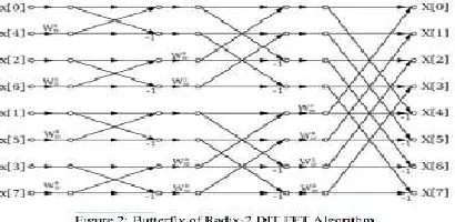
Frequency Division Multiplexing (OFDM) is such a reliable option to accomplish the above requirement. The algorithms of FFT can be grouped into fixed-radix, mixedradix and split radix algorithms in a rough manner [5]. The basic categories of algorithms of FFT include - Decimation infrequency (DIF) and the Decimation-in-time (DIT) as shown in Figure 1. Both of these algorithms depend on disintegration of transformation of an N-point sequence into many subsequences in a successive manner. There is no major difference between them as far as complexity of computation is concerned.
There are two types with respect to FFT algorithm devised by Cooley and Tukey - Decimation-in-Time algorithm (DIT) and Decimation-in-Frequency algorithm (DIF). In case of DIT the input sample is used bit reversal order while the output of DIT FFT coefficients is generated in natural order.In case of DIF the input sample is used in natural order while the output of DIF FFT coefficient is generated in bit reversed order.
The most popular architectures for computing FFT is the pipelined FFT, which consist of a series of a stages that process the data. Each stage contains a butterfly and a twiddle factor multiplier.
input sample is used bit reversal order while the output of DIT FFT coefficients is generated in natural order.
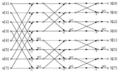
Figure 3, shows the butterfly of radix-2 DIF FFT algorithm. In case of DIF the input sample is used in natural order while the output of DIF FFT coefficient is generated in bit reversed order.
The fast Fourier transform (FFT) is an efficient computational method to calculate the discrete Fourier transform (DFT), which is the discrete version of the Fourier transform. FFT has been widely used in digital signal processing applications, such as image processing, orthogonal frequency division multiplexing (OFDM), spectrum analyzers and medical signal processing.
III.PROPOSED SYSTEM
In this proposed system we are using the Parallel prefix adder in order to calculate the 16 bit radix-2 fft algorithm. VLSI Integer adders find applications in Arithmetic and Logic Units (ALUs), microprocessors and
memory addressing units. Speed of the adder often decides the minimum clock cycle time in a microprocessor. The need for a Parallel Prefix Adder (PPA) is that it is primarily fast when compared with a ripple carry adder. PPA is a family of adders derived from the commonly known carry look ahead adders. These adders are suited for additions with wider word lengths. PPA circuits use a tree network to reduce the latency to O(log n) where ‘n’ represents the
number of bits. This chapter deals with the design proposal and implementation of new prefix adder architecture for 8-bit, 16-bit, 32-bit and 64-bit addition. The proposed architectures have the least number of computation nodes when compared with existing one’s. This reduction in hardware of the proposed architectures helps to reap a benefit in the form of reduced power and power-delay product.
Parallel-prefix adders, also known as carry-tree adders, pre-compute the propagate and generate
signals [6].The main disadvantage of
Fig 4: Parallel Prefix A d d itio n Op eratio n
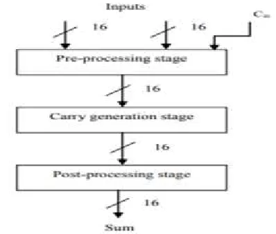
Parallel Prefix Adder contains three stages of operation.The first stage is the pre-processing stage and this stage is also called as prefix stage[8]. In this stage Generate and propagate are from each pair of inputs. Propagate gives XOR operation of input bits
P=A xor B.
Generate gives AND operation of input bits G=A and B.
The second stage of parallel prefix adder is Carry Generation Stage. In this stage, carry is generated for each bit and this is called as carry generate (Cg ).
The carry propagate and carry generate is generated for the further operation but final cell present in the each bit operation gives carry.The last bit carry will help to produce sum of the next bit simultaneously till the last bit.
Carry generate and carry propagate equations are given below as:
The final Stage of parallel prefix adder is post processing stage.Here the carry of a first bit is XOR ed with next bits of propagates and the o/p is given as sum and it is given by the equation as shown below:
The basic architecture of a 16 bit parallel prefix addition is shown below:
Fig 5: Architecture of PPA Adder.
Fig 6: Illustration of 16 bit PPA.
Now after calculating the prefix addition we have to calculate the sum[9]. As we all know that we use add half adder for addition of two bits.Full adder is used for the addition of three bits and produces sum and carry as outputs. For the addition of n-bits we use parallel prefix addition. So after applying this procedure we get the final outputs as a+jb,a-jb.
IV. RESULTS
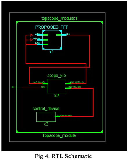
Fig 4. RTL Sch ematic
Fig 5. Ou tp u t wav efo rm
V.CONCLUSION
carries in parallel. The parallel prefix adders are more favorable in terms of speed when compared with other adders such as carry look ahead adder, carry select adder and carry skip adder. VLSI, in modern day technology has seen extensive use of PPA with a better delay performance. These pre-compute the carries and thus have upper hand over the commonly used Ripple Carry Adder (RCA). Addition has been an indispensible operation in most of the widely used applications. However, because of the structure of the configurable logic and routing resources in FPGAs, parallel-prefix adders will have a different performance than VLSI implementations. In particular, most modern FPGAs employ a fast-carry chain which optimizes the carry path.
VI. REFERENCES
[I] J. w. Tukey and J. w. Cooley, "An algorithm for the machine computation of the complex Fourier series," math computation, volumel9, year 1965, PP. 297-301.
[2] D.G. Manolakis and John G. Proakis,
"Digital Signal
ProcessingPrinciples,Algorithms, and Applications," year 2003, third edition, chapter 6, of Prentice Hall, India.
[3] Haining Jiang , Shanghai Jiao Tong Univ., China , Hanwen Luo , Jifeng Tian , Wentao Song, "An Area Efficient FFT Architecture for Orthogonal frequency division multiplexing DVB," Consumer Electronics, IEEE Trans. (Volume:51 , Issue: 4 ), 2005.
[4] Johnson, S.G. ; Frigo, M, " A modified split radix FFT with fewer arithmetic operations," Signal Processing, IEEE Transactions, year 2007, volume 55, issue I. [5] Rabiner S. and A. V. Oppenh., "Digital Signal Processing," PHI of India, 2002,Chapter-9.
[6] N. H. E. Weste and D. Harris, CMOS VLSI Design, 4th edition, Pearson–Addison-Wesley, 2011.
[7] R.P. Brent and H.T. Kung. A Regular
Layout for Parallel Adders. IEEE
Transactions on Computers, 3 1:260-264, Mar. 1982. Ncil Burgess.
[8] The Flagged Prefix Adder for Dual Additions. In Proc. SPIE ASPAAI-7, volume 3461, pages 567-575, San Diego, Jul. 1998.
[9] Eleanor Chu and Alan George, "Inside the FFT Black Box Serial and Parallel Fast Fourier
Transform Algorithms," CRC, New York, 2000.
[10] T. Hitana and A. K. Deb, “Bridging concurrent and non-concurrent error detection in FIR filters,” in Proc. Norchip Conf., Nov. 2004, pp. 75–78.
[11] S. Pontarelli, G. C. Cardarilli, M. Re, and A. Salsano, “Totally fault tolerant RNS based FIR filters,” in Proc. 14th IEEE Int. On-Line Test Symp. (IOLTS), Jul. 2008, pp. 192–194.
[12] B. Shim and N. R. Shanbhag, “Energy-efficient soft error-tolerant digital signal processing,” IEEE Trans. Very Large Scale Integr. (VLSI) Syst., vol. 14, no. 4, pp. 336– 348, Apr. 2006.
[13] E. P. Kim and N. R. Shanbhag, “Soft
Comput., vol. 61, no. 3, pp. 323–336, Mar. 2012.
[14] J. Y. Jou and J. A. Abraham, “Fault-tolerant FFT networks,”IEEE Trans. Comput., vol. 37, no. 5, pp. 548–561, May 1988.
[15] S.-J. Wang and N. K. Jha,
“Algorithm-based fault tolerance for FFT