Performance Analysis of MIMO-Frequency Diverse Array Radar
with Variable Logarithmic Offsets
Wasim Khan1, *, Ijaz M. Qureshi2, Abdul Basit1, Aqdas Naveed1, and Adnan Umar1
Abstract—Frequency diverse array (FDA) uses a small frequency increment at each antenna element to get a range, angle and time dependent beam pattern. Although linear frequency offset is used in most radar systems, nonlinear frequency offset is also very useful for analyzing FDA radar. A logarithmic frequency offsets based FDA (log-FDA) removes the inherent periodicity of FDA beam pattern to get a single maxima in area of interest. Multiple input multiple output frequency diverse array (MIMO-FDA) radar has also been presented recently to provide some improvements compared to FDA radar. In this paper, a hybrid scheme has been proposed in which each subarray of MIMO-FDA uses a variable logarithmic offset. The resultant system, called MIMO-log-FDA, uses not only a different logarithmic offset, but also unique waveform in each subarray. Different logarithmic offsets have contributed in terms of getting more control on width of beam pattern, while the different waveforms have provided diversity, which can be exploited at the receiver of the proposed system. Some improvements in transmit beam patterns have been shown for MIMO-log-FDA, followed by detailed signal model for better estimation of target at the receiving side. Performance analysis has also been done in terms of signal to interference plus noise ratio (SINR) and Cramer-Rao lower bound (CRLB). Simulation and results have verified the effectiveness of proposed scheme by comparing it with Log-FDA and MIMO-FDA radar.
1. INTRODUCTION
A flexible antenna array called frequency diverse array (FDA) [1] was originally proposed during last decade, which provided additional degree of freedom for existing radar applications. It used a small frequency offset between the adjacent elements of an array to generate a beam pattern as a function of frequency offset, time, range and angle. Application of FDA to various modes of operations in radar systems was presented in [2], while the periodicity of beam pattern in time, range and angle was explored in [3]. Two FDA based patents were issued to analyze the increasing degree of freedom due to time, range and angle dependency of beam pattern [4, 5]. A linear FDA was proposed in [6] to mitigate the range ambiguous clutters, which showed a considerable assistance in detecting relatively slow moving targets. The authors of [7] explored the radiation characteristics of an FDA to show its beam scanning feature. It was also proved that the scanning speed was related to frequency offset used between two neighboring antenna elements. The range and angle coupled beamforming with frequency diverse chirp signals was explored in [8]. Additionally, FDA range-angle dependent beamforming ability to suppress interferences at different ranges and directions was examined in [9], which resulted in an improved SINR compared to phased array radar (PAR).
The frequency offset across the FDA elements plays a very important role in improving the overall performance of an FDA radar in terms of controlling range-angle dependency and spatial distribution of generated beam pattern [10, 11]. Therefore, researchers have shown great interest in investigating the proper selection of frequency offset between the adjacent elements of a linear FDA for improved
Received 9 January 2016, Accepted 29 January 2016, Scheduled 9 February 2016 * Corresponding author: Wasim Khan ([email protected]).
performance. Recently, an FDA with an adaptive frequency offset selection scheme was proposed in [12] to maximize the output signal to interference noise ratio (SINR) criteria. Similarly, an FDA with a time-dependent frequency offset was proposed in [13] to achieve an improved time-dependent beam pattern for a given target range and direction. A new dimension of FDA based research applied non-uniform offsets across antenna elements to uncover some new interesting features of FDA radar. In [14], the inter-element spacing of FDA proportional to the signal wavelength was studied, which showed an improved range-angle localization of targets. Moreover, a logarithmically increasing inter-element frequency offset across antenna elements was presented in [15], which generated a single-maximum beam pattern for an arbitrary value of frequency offset, as well as suppressed interferences in region of interest. Another variation in FDA called MIMO-FDA radar [16–20] was reported in recent literature to exploit the benefits of MIMO and FDA radars. MIMO-FDA radars system combined the advantages of both radars, while mitigating the shortcomings. In [16], the pseudo-noise (PN) codes sent at slightly different frequencies were combined to give rise to a MIMO waveform having both angle and range as a function. Additionally, the concept of subarrayed FDA in [17] helped in estimating the target positions by using the beamspace-based MUSIC algorithm. Avoiding deceptive jamming to differentiate between true and false targets through MIMO-FDA was explored in [18]. A novel approach to jointly estimate target range and angle was presented in [19], which used an appropriate frequency offset value for MIMO-FDA to achieve improved range angle beam pattern for better detection and estimation performance. MIMO-FDA with logarithmic offset was proposed in [20], which generated several beam-pattern maxima for targets present in different range bins. The study only focused on generating a single maxima for each target through signal processing at the transmit side.
In this paper, a novel MIMO-FDA radar architecture with logarithmic frequency offset (MIMO-log-FDA) is proposed. Unlike [20], where same frequency offset value was used in each subarray, we apply a different frequency offset value in each subarray to add an extra degree of freedom in terms of controlling the beam pattern. In addition, the receiver side of the proposed MIMO-log-FDA is also presented and analyzed. The motivation for this design is driven by the fact that logarithmic offset based radar system can produce beam patterns with ability to reject all interferences in vicinity of the desired target, resulting in improvement of SINR. First part of the paper focuses on transmit side to show the impact of using different non-uniform offsets, i.e., logarithmic offset. It is observed that the variation in logarithmic offsets contributes to controlling the beam width of transmitted beam pattern. Moreover, numerous energy focused beams towards a particular target may provide a superior performance of the proposed radar compared to existing MIMO-FDA and MIMO-log-FDA radar. Likewise, the second part of the paper provides a detailed received signal model for MIMO-log-FDA. Performance analysis is also provided in terms of signal to interference plus noise ratio (SINR), as well as Cramer-Rao lower bound (CRLB) on target range and angle estimations. The results are compared with the existing FDA and MIMO-FDA, which clearly exhibit that the proposed MIMO-log-FDA outperforms existing FDA radar designs.
The organization of paper is as follows. Section 2 will give necessary details about data model of log-FDA followed by proposed MIMO-log-FDA radar in Section 3. SINR and CRLB are derived in Section 4. This is followed by some discussions on results in Section 5 and concluding remarks in Section 6.
2. DATA MODEL FOR LOG-FDA
In this section, some preliminaries information about logarithmic offset based FDA is presented. Consider an array of M elements with uniform spacing between the elements. The signal sent by mth element is
sm(t) =wmej2πfmt (1)
The radiated frequencyfm will be
fm=f0+ Δfm (2)
wheref0 is the carrier frequency, and the frequency offset Δfm can be given as
whereδ is the configurable parameter for adjusting logarithmic offset. The frequency offset across each antenna element in logarithm instead of linear offset can be seen. Considering a point target in space, the pattern of transmitted signal can be written as follows
x(t;r0, θ) =
M−1
m=0 sm
t− rm c
=
M−1
m=0
wme−j
2πfm
t−r0−mdc sinθ
(4)
where rm =r0−mdsinθ is the range of target from mth antenna element and c is speed of light. By applying fm from Eq. (2) and the assumption that f0 log(M)δ, we will get
x(t;r0, θ) =ej2πf0(t−r0/c)×
M−1
m=0
wmej2πlog(m+1)δ(t−r0/c)ej2πf0mdsinθ/c (5)
The overall signal arrived at a far-field point is given in Eq. (5). It will produce a single maxima at the target location and remove the periodicity in the maxima. Term inside summation can be taken as array factor, and its magnitude square is the transmit beam pattern. For a fixed value of t, the beam pattern will be range- and angle-dependent beam pattern.
3. PROPOSED MIMO-LOG-FDA RADAR
The log-FDA radar uses only one value of configuration parameterδ to apply logarithmic offset across the transmit array. Likewise, existing MIMO-Log-FDA radar uses the same configuration parameter in each subarray. However, in this work, we apply different configuration parameters in subarrays to produce multiple beam patterns of variable width. The proposed system also uses the approach of overlapped subarrays to achieve maximum transmit gain. In order to define subarrays in a transmit array of M elements, a M ×1 vector Pn is defined which contains 0 and 1 as entries. For the nth
subarray, a 1 in the vector at a particular index shows that the antenna corresponding to that index belongs to thenth subarray, while a zero means that the corresponding antenna does not belong to the nth subarray. If each subarray hasMtelements, where 1< Mt< M, then the number of 1’s inPnisMt,
and the number of 0’s isM−Mt. Moreover, aMt×1 vector for a particular subarray can be obtained
asMt=PnM, where stands for Hadamard product. Since different configuration parameters are
used in the subarrays, offset selection will be slightly different from log-FDA. The frequency radiated by the mth element of the nth subarray will be
fm,n=f0+ Δfm,n (6)
wheref0 is the carrier frequency and Δfm,n the frequency offset given as
Δfm,n = log(m+ 1)·δn, 0≤m≤Mt−1, 1≤n≤N (7)
Here Mt represents number of elements in each subarray while N represents the total number of
subarrays.
3.1. Signal Model
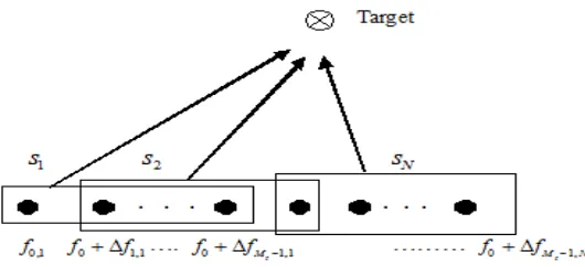
Consider a transmit array ofM elements partitioned into N overlapping subarrays, as shown in Fig. 1. Since the transmit array is divided into equal subarrays, so the number of elements in each subarray can be given byMt=M−N+ 1. The signal radiated by thenth subarray in the far field can be given
as
Xm,n(t) =ρsn(t)wm,nej2πfm·nt (8)
where ρ = M/N is the energy transmitted by each subarray and wm,n the weight given to the mth
element of the nth subarray. The nth subarray contains Mt active weights andM −Mt zeros weights
corresponding to inactive elements. sn(t) is the waveform transmitted by the nth subarray. Overall
signal observed in far field can be written as
x(t;r0, θ) =
M−1
m=0
N
n=1 Xm,n
t− rm c
Figure 1. MIMO-FDA with different logarithmic offsets.
By using far-field approximation, i.e., rm =r0+mdsin(θ), the signal in Eq. (9) can be written as
x(t;r0, θ)≈
M−1
m=0
N
n=1
ρsn(t)wm,ne−j
2πfm,n
t−r0−mdc sinθ
(10)
Using the value offm,n from Eq. (6)
x(t;r0, θ) =ej2πf0(t−r0/c)×
M−1
m=0
N
n=1
ρsn(t)wm,nej2π(f0mdsinθ/c+log(m+1)δn(t−r0/c)) (11)
Here the signal in Eq. (11) can be obtained by assumingf0log(M)δn. The term inside the summation
can be taken as the array factor, and its square is the transmit beam pattern. Beam pattern transmitted by the nth subarray can be given as
Bn(t, r0, θ)≈ |AFn(t, r0, θ)|2 ≈
M−1
m=0
N
n=1
ρsn(t)wm,nej2π(f0mdsinθ/c+log(m+1)δn(t−r0/c))
2
(12)
It can be observed that beam pattern depends upon the weights given to a particular subarray. Therefore, we can adjust these weights properly to get a single maxima which is one of the main attributes of logarithmic offset based radar systems.
Signal reflected from a far-field target will contain each of theN waveforms transmitted by transmit array. It is important to mention that we use a uniform linear array at the receiver, where waveforms will be matched filtered to get desired information. For a receiver array of R antenna elements, the signal received on therth element can be given as
mr(t, θ) =ρ N
n=1
Mt−1
m=1
βsn(t−τn−τr)ej2πfm,n(t−τn−τr) (13)
Here β is complex valued reflection coefficient for a target in the far field. τn and τr are time delays on
transmit and received side, respectively, which can be further written as
τn = τ20 −dt
sinθ
c =
r−dtsinθ
c (14)
τr = τ20 −dr
sinθ
c =
r−drsinθ
c (15)
where τ0 = 2r/c, dt and dr are distance between elements of transmit array and received array. θ
is the angle of target while r is the range of target. By applying narrow band assumption that sn(t−τ) ≈ sn(t−τ0) and matched filtering the nth waveform on rth element, we will get the data vector
dn,r≈ρβe−j4π
fn
After applying the value of fn in Eq. (16) and using the approximation that frequency increment is
negligible compared to fundamental frequency in second exponential term of Eq. (16), the signal can be further written as
dn,r ≈ρβe−j4π
f0
cre−j4πΔfnc rej2π f0
c[dtsinθ+drsinθ] (17)
Here Δfn is offset given to the nth subarray. Since the rth element will receive all the signals, the
output of this element can be written as a vector
d=ρβ˜u(θ, r)ej2πfc0drsinθ (18)
where ˜β =β·e−j4πfc0r and u(θ, r) is a transmit steering vector with extended length due to a different logarithmic frequency offset in each subarray and given as
u(θ, r) =1 ejψ1 ej2ψ1 . . . ej(Mt−1)ψ1 1 ejψ2 ej2ψ2 . . . ej(Mt−1)ψ2 . . .1 ejψN ej2ψN . . . ej(Mt−1)ψN (19) where,
ψ1 =
2πf0
c dtsinθ−4π Δf1
c r (20a)
ψ2 =
2πf0
c dtsinθ−4π Δf2
c r (20b)
· · ·
ψN =
2πf0
c dtsinθ−4π ΔfN
c r (20c)
Similarly, the received steering vector can be written as
v(θ) =
1, ej2πfc0drsinθ . . . ej2π f0
c (r−1)drsinθ
(21)
Using Eqs. (20) and (21), virtual data vector for target signal can be written as
ds= dT1 dT2 dT3 . . . dNT T =ρβ˜v(θ)⊗u(θ, r) (22)
where ⊗stands for the Kronecker product and (·)T the transpose operator. AssumingQ interferences in background of target and introducing noise term, the final form can be written as
d=ds+di+dn=ρβ˜v(θ)⊗u(θ, r) +
Q
q=1 ˜
βqv(θq)⊗u(θq, rq) +zn (23)
znis the noise vector. Noise is assumed to be zero mean white circularly Gaussian noise with covariance σ2IN R, whereIN R is theN ×R identity matrix.
3.2. Beamforming and Range-Angle Estimation
Using a non-adaptive conventional beamformer [21], weight vector can be given by wR = v(θd) ⊗
u(θd, rd). The received normalized beam pattern can be written as
Br(θ, r) =
wrH(v(θ)⊗u(θ, r))2
|wH
r v(θd)⊗u(θd, rd)|2
(24)
where (θd, rd) is the angle and range of a desired target. Putting the value of weights, final beam pattern
will be
Br(θ, r) = |
[v(θ)⊗u(θd, rd)] [v(θ)⊗u(θ, r)]|2 v(θd)⊗u(θd, rd)4
The next step is to estimate the angle and range of a target. For non-adaptive beamformer, the angle can be estimated as
ˆ θ= arg
max
θd
wHr v(θd)⊗u(θd, rd)
2
(26)
Likewise, the range can be estimated as
ˆ r= arg
max
rd
wHr v(θd)⊗u(θd, rd)
2
(27)
After completing this step, we have the estimates of both angle and range. Therefore, we can exactly locate the target in range-angle dimension, i.e., (θd, rd). Estimation performance of different radar
systems will be analyzed in subsequent section.
4. PERFORMANCE ANALYSIS OF MIMO-LOG-FDA
In this section, performance analysis of the proposed radar has been done in terms of output signal to interference plus noise ratio and Cramer-Rao lower bound.
4.1. SINR
For SINR, covariance matrix can be given as
Ci+n=ρ2 Q
i=1
σi2(v(θi)⊗u(θi, ri))
v(θi)⊗uH(θi, ri)
+σ2nI (28)
where αi and αn are the variances of reflection coefficient of interference and noise, respectively. It is
important to mention that FDA beam pattern is time dependent as well as angle and range dependent. Thus to reduce its complexity, we can take one parameter as constant to show its dependence in other two parameters. Here we will fix time to make it a range-angle dependent beam pattern. In this paper, we take snapshot of pattern at precise time given as t= 1/Δf. This little assumption makes it easier for us to model the covariance matrix. SINR for MIMO-log-FDA can be given as
SINR = ρ 2σ2
dwHr v(θd)⊗u(θd, rd)
2
wH
r Ci+nwr
(29)
By putting the values, Eq. (29) can be further written as
SINR = ρ
2σ2
dv(θd)2u(θd, rd)2
2
vH(θd)⊗uH(θd, rd)
Q
i=1 ρ2σ2
i(v(θi)⊗u(θi, ri))(v(θi)⊗u(θi, ri))H +σn2I))
v(θd)⊗u(θd, rd)
(30) Using the fact that u(θd, rd)2 =N and v(θd)2=R, SINR can be further simplified to
SINR = ρ
2σ2
dN2R2
ρ2
Q
i=1
σ2i |(v(θd)⊗u(θd, rd))Hv(θi)⊗u(θi, ri)|2+σ2nN R))
(31)
4.2. CRLB
Parameter vector to be estimated can be givenγ= [θ, r]T. Observed signald has the meanμand covariance matrixR given as
μ = βu(θ, r) (32a)
R = σ2IN R (32b)
The Fisher information matrix can be derived as
J = 2ReDHγi(γ)(R−n1)Dγj(γ)
(33)
= 2β 2
σ2
n
2ω21C1 ω1ω2C1 ω1ω2C1 ω22C1
(34)
where,
ω1 =
2πf0dcosθ
c (35a)
ω2 =
4πΔf1
c +
4πΔf2 c . . .
4πΔfN
c (35b)
C1 =
N
n=1
Mt−1
m=0
n·m2 (35c)
Since 2β2
σn2 is the signal to noise ratio (SNR), CRLB matrix can be obtained as
J−1= 1 2·SNR·C2
ω22C1 −ω1ω2C1
−ω1ω2C1 2ω12C1
(36)
where
C2 = 2ω12C1·ω22C1−ω21ω22C12 (37) Finally, CRLB for both estimates can be given as
CRLBθθ = 1
2·SNR·C2ω 2
2C1 (38)
CRLBrr = 1
2·SNR·C2ω 2
1C1 (39)
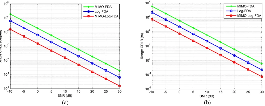
It is important to mention that the extended data vector due to multiple waveforms and logarithmic frequency offset allows a better estimate than existing FDA radar.
5. SIMULATIONS AND RESULTS
Consider an FDA array with 12 transmit antenna elements divided into 3 overlapped subarrays, where each subarray consists of 10 elements. The fundamental frequency is f0 = 10 GHz, and configurable parameters for each subarray of MIMO-Log-FDA are δ1 = 15 kHz, δ2 = 30 kHz and δ = 45 kHz, respectively. For MIMO-FDA and Log-FDA radar,δ1 = 15 kHz will be used throughout the simulation. The distance between the antenna elements is taken asλ/4 to avoid physical reallocation of the antenna elements in case of changing the configuring parameter δ. We assume a stationary target present at θ= 10◦ and r = 40 km throughout the simulation and no mutual coupling between antenna elements. Noise is assumed to be zero mean white circularly Gaussian noise. The first part of simulation presents results for transmit side, while the second part presents comparisons of beam pattern on receiver side followed by performance analysis in the last part of simulation.
(a)
(b) (c)
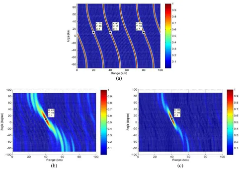
Figure 2. Normalized transmit beam patterns of (a) MIMO-FDA, (b) log-FDA, (c) MIMO-log-FDA.
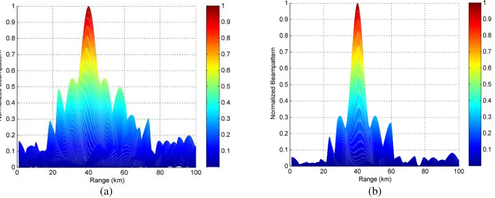
of uniform offsets. Since MIMO-log-FDA radar provides us with an extra degree of freedom by allowing a different logarithmic offset in each subarray, the beam pattern of MIMO-log-FDA radar is better than log-FDA in terms of spread in range dimension as well as side lobes. Less spread can be attributed to larger logarithmic frequency offset used in the second and third subarrays. This less spread in range dimension due to increase in logarithmic offset has already been shown in [20], where sharpness in range dimension increases due to larger logarithmic offset and vice versa. Side lobes levels for log-FDA and MIMO-log-FDA in terms of angle and range dimension are shown in Fig. 3 and Fig. 4, respectively, by plotting only angle and range profile of both radar systems. Figs. 3(a) and 3(b) show the side lobe levels of both radars in angle dimension. Clearly, side lobe levels of the proposed radar are lower than log-FDA radar. Likewise, Fig. 4(b) exhibits lower side lobe levels in range dimension for the proposed radar than log-FDA radar presented in Fig. 4(a). Thus by properly handling non-uniform offset, an improvement in transmit beam pattern can be achieved. MIMO-FDA is not compared due to its inability to produce single maximum in desired region.
(a) (b)
Figure 3. Normalized transmit beam patterns in angle dimension, (a) log-FDA, (b) MIMO-log-FDA.
(a) (b)
Figure 4. Normalized transmit beam patterns in range dimension, (a) log-FDA, (b) MIMO-log-FDA.
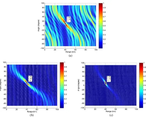
logarithmic offset based systems exhibit better performance than other radar systems due to single maximum for target at the transmit side. Moreover, performance of the proposed system is better than log-FDA in terms of suppression of interferences. This can be attributed to variable logarithmic offset in each subarray.
(a)
(b) (c)
Figure 5. Normalized transmit beam patterns of (a) MIMO-FDA, (b) log-FDA, (c) MIMO-log-FDA.
(a) (b)
Figure 7. (a) CRLB versus SNR for angle estimation, (b) CRLB versus SNR for range estimation.
6. CONCLUSION AND FUTURE WORK
A MIMO-FDA radar with logarithmic frequency offset has been proposed to improve the estimation performance of existing radar systems. Transmit array is divided into multiple overlapped subarrays, each modulating a different waveform and logarithmic frequency offset. It has been observed that a different logarithmic offset in each subarray not only allows a single maximum instead of periodic multiple maxima, but also helps in better focusing of beam pattern by using a larger logarithmic frequency offset. Transmit and received beam pattern of the proposed system are plotted against the log-FDA and MIMO-FDA to show the improvements. Performance analysis has also been done in terms of SINR and CRLB to prove the effectiveness of proposed system. In future work, interference rejection capability of MIMO-log-FDA radar can be analyzed by using adaptive beamformers.
REFERENCES
1. Antonik, P., M. C. Wicks, H. D. Griffiths, and C. J. Baker, “Frequency diverse array radars,”Proc. IEEE Radar Conf., Apr. 2006.
2. Antonik, P., M. C. Wicks, H. D. Griffiths, and C. J. Baker, “Multimission multi-mode waveform diversity,” Proc. IEEE Radar Conf. Dig., 580–582, Verona, NY, USA, Apr. 24–27, 2006.
3. Secmen, M., S. Demir, A. Hizal, and T. Eker, “Frequency diverse array antenna with periodic time modulated pattern in range and angle,”IEEE Conference on Radar, 427–430, 2007.
4. Antonik, P. and M. C. Wicks, “Method and apparatus for simultaneous synthetic aperture and moving target indication,” U.S. Patent 20 080 129 584, Jun. 5, 2008.
5. Wicks, M. C. and P. Antonik, “Frequency diverse array with independent modulation of frequency, amplitude, and phase,” U.S. patent 7,319,427, Jan. 15, 2008.
6. Baizert, P., T. B. Hale, M. A. Temple, and M. C. Wicks, “Forwardlooking radar GMTI benefits using a linear frequency diverse array,” Electronics Letters, Vol. 42, No. 22, 1311–1312, Oct. 2006. 7. Huang, J., K. F. Tong, and C. J. Baker, “Frequency diverse array with beam scanning feature,”
Proc. IEEE 2008 Ant. and Prop. Soc. Intl. Symp., 1–4, Jul. 5–11, 2008.
8. Higgins, T. and S. Blunt, “Analysis of range-angle coupled beamforming with frequency diverse chirps,” Proceedings of the 4th International Waveform Diversity & Design Conference, 140–144, Orlando, FL, Feb. 2009.
10. Zhuang, L. and X. Z. Liu, “Precisely beam steering for frequency diverse arrays based on frequency offset selection,”Proc. Int. Radar Conf., 1–4, 2009.
11. Chen, Y.-G., Y.-T. Li, Y.-H. Wu, and H. Chen, “Research on the linear frequency diverse array performance,” Proc. IEEE 10th Int. Conf. on Signal Processing, 2324–2327, Beijing, Oct. 24–28, 2010.
12. Shao, H., J. Li, H. Chen, and W. Q. Wang, “Adaptive frequency offset selection in frequency diverse array radar,”IEEE Antennas and Wireless Propagation Letters, Vol. 13, 1405–1408, 2014.
13. Khan, W. and I. M. Qureshi, “Frequency diverse array radar with time-dependent frequency offset,” IEEE Antennas and Wireless Propagation Letters, Vol. 13, 758–761, 2014.
14. Wang, W.-Q., H. C. So, and H. Shao, “Nonuniform frequency diverse array for range-angle imaging of targets,” IEEE Sensors Journal, Mar. 2014.
15. Khan, W., I. M. Qureshi, and S. Saeed, “Frequency diverse array radar with logarithmically increasing frequency offset,” IEEE Antennas and Wireless Propagation Letters, Vol. 99, 1–5, 2015. 16. Sammartino, P. F., H. D. Griffiths, and C. J. Baker, “Frequency diverse MIMO techniques for
radar,”IEEE Trans. on Aerospace and Electronic Systems, Vol. 49, No. 1, 201–222, 2013.
17. Wang, W.-Q. and H. C. So, “Transmit subaperturing for range and angle estimation in frequency diverse array radar,” IEEE Trans. Signal Process., Vol. 62, No. 8, 2000–2011, 2014.
18. Xu, J., G. Liao, S. Zhu, and H. C. So, “Deceptive jamming suppression with frequency diverse MIMO radar,”Signal Processing, Vol. 113, 9–17, 2015.
19. Xu, J., G. Liao, S. Zhu, L. Huang, and H. C. So, “Joint range and angle estimation using MIMO radar with frequency diverse array,”IEEE Trans. Signal Process., Vol. 63, No. 13, 3396–3410, 2015. 20. Khan, W., I. Qureshi, A. Basit, and W. Khan, “Range bins based MIMO frequency diverse array radar with logarithmic frequency offset,” IEEE Antennas and Wireless Propagation Letters, DOI 10.1109/LAWP.2015.2478964, 2015.
21. Van Trees, H. L.,Optimum Array Processing, Wiley, New York, 2002.
22. Renaux, A., P. Forster, E. Chaumette, and P. Larzabal, “On the high SNR conditional maximum-likelihood estimator full statistical characterization,”IEEE Trans. Signal Process., Vol. 54, No. 12, 4840–4843, Dec. 2006.
23. Li, J., L. Xu, P. Stoica, K. W. Forsythe, and D. W. Bliss, “Range compression and waveform optimization for MIMO radar: A Cram´er-Rao bound based study,” IEEE Trans. Signal Process., Vol. 56, No. 1, 218–232, Jan. 2008.