Available online: https://edupediapublications.org/journals/index.php/IJR/ P a g e | 1399
Implementation of Quantum-Dot Cellular Automata Based
Efficient N-Bit Bcd Adders Using Verilog
Bikkina Sri Lakshmi Durga Bhavani 1, M.Sathibabu 2
1P.G Student, VLSI
2 Assistant Professor, Department of Electronics and Communication Engineering, Kits
engineering College, divili.
Abstract: Among the emerging technologies recently proposed as alternatives to the classic
CMOS, Quantum-dot cellular automata (QCA) is one of the most promising solutions to design
ultra low power and very high speed digital circuits. Efficient QCA-based implementations have
been demonstrated for several binary and decimal arithmetic circuits, but significant
improvements are still possible if the logic gates inherently available within the QCA technology
are smartly exploited. This brief proposes a new approach to design QCA-based BCD adders.
Exploiting innovative logic formulations and purpose designed QCA modules, computational
speed significantly higher than existing counterparts are achieved without sacrificing either the
occupied area or the cells count.
Keywords: QCA, CMOS, BCD
1.INTRODUCTION
Optimizations in VLSI have been done on three elements: Area, Power and Timing
(Speed).Area advancement implies decreasing the space of rationale which involve on the bite
the dust. This is done in both front-end and back-end of structure. In front-end plan, appropriate
depiction of improved Boolean articulation and evacuating unused states will prompt limit the
gate/transistor usage. Parcel, Floor arranging, Placement, and directing are perform in back-end
of the plan which is finished by CAD device .The CAD apparatus have a particular calculation
for each procedure to create a territory effective structure like Power advancement. Power
streamlining is to lessen the power dispersal of the plan which endures by working voltage,
working recurrence, and exchanging movement. The initial two elements are only determined in
plan imperatives yet exchanging movement is a parameter which shifts powerfully, in view of
Available online: https://edupediapublications.org/journals/index.php/IJR/ P a g e | 1400 meeting the client requirements in productive way with no infringement generally, enhancing
execution of the plan.
Quantum-speck cell automata (QCA) are an appealing rising innovation appropriate for
the improvement of ultra thick low-control elite advanced circuits. Quantum-speck cell automata
(QCA) which utilizes exhibit of coupled quantum dabs to execute Boolean rationale work. The
upside of QCA lies in the greatly high pressing densities conceivable because of the little size of
the specks, the rearranged interconnection, and the to a great degree low power defer item. An
essential QCA cell comprises of four quantum dabs in a square cluster coupled by passage
hindrances. Electrons can burrow between the dabs, yet can't leave the cell. In the event that two
abundance electrons are set in the cell, Coulomb repugnance will drive the electrons to dabs on
inverse corners. There are therefore two enthusiastically proportionate ground state polarizations
can be marked rationale "0"and "1".The fundamental building squares of the QCA engineering
are AND,OR and NOT. By utilizing the Majority gate we can diminish the measure of delay.i.e
by figuring the engendering and generational conveys.
2. Existing System
The principle goal of this paper is to perform both BCD expansion and BCD subtraction
in a solitary circuit with least number of gates check and steady info. To accomplish the activity
of reversible BCD expansion and subtraction in a solitary circuit two new gates are proposed
which are advanced to such an extent that it doesn't have any limitations of reversible gates as
made reference to above. It has been demonstrated that the proposed reversible BCD math circuit
is superior to anything the current rationales in the writing; as far as number of trash yields,
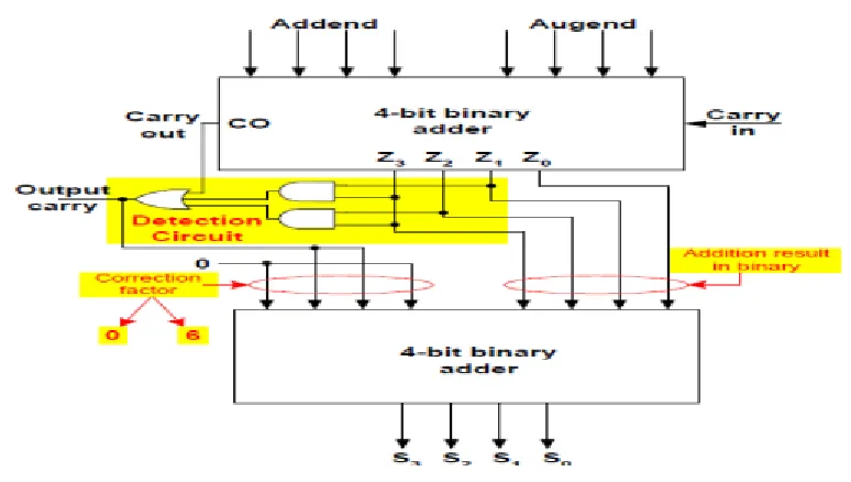
Available online: https://edupediapublications.org/journals/index.php/IJR/ P a g e | 1401 Fig 1: The conventional block diagram of BCD.
BCD or on the other hand Binary Coded Decimal is that number framework or code which
has the twofold numbers or digits to speak to a decimal number. A decimal number contains 10 digits
(0-9). Presently the proportional paired numbers can be discovered of these 10 decimal numbers. If
there should be an occurrence of BCD the parallel number shaped by four paired digits, will be the
comparable code for the given decimal digits. In BCD we can utilize the double number from
0000-1001 just, which are the decimal proportionate from 0-9 individually. Assume in the event that a
number have single decimal digit, it's comparable Binary Coded Decimal will be the particular four
double digits of that decimal number and on the off chance that the number contains two decimal
digits, it's identical BCD will be the separate eight paired of the given decimal number. Four for the
principal decimal digit and next four for the second decimal digit. It might be cleared from a
precedent.
3. PROPOSED SYSTEM
QCA Majority Gate:
The QCA greater part gate plays out a three-input rationale work. Accepting the sources
of info are A ,B and C, the rationale capacity of the greater part door is M =AB+BC+CA
QCA BCD Adder
Available online: https://edupediapublications.org/journals/index.php/IJR/ P a g e | 1402 4-bit BCD result. Fig. 1 demonstrates the square outline of ordinary BCD adder. The circuit must
incorporate the remedy rationale to create substantial BCD yield. Two 4-bit BCD numbers X and
Y alongside convey input is included utilizing ordinary 4-bit parallel adder, 4-bit whole and a do
is taken. In the event that the convey yield is set or if the outcome is more noteworthy than nine,
twofold 0110 is added to the transitional whole yield with the assistance of second stage 4-bit
parallel adder circuit.
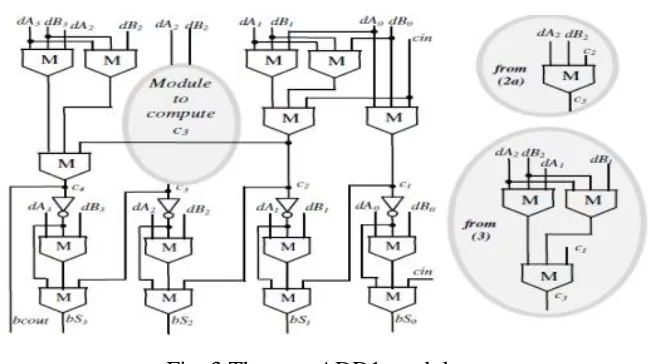
Fig 2: BCD adders using QCA.
A novel QCA adder configuration is exhibited that lessens the quantity of QCA cells
when contrasted with recently revealed structures. We show that it is conceivable to plan a CLA
QCA one-piece adder, with indistinguishable diminished equipment from the bit-sequential
adder, while holding the less difficult timing plan and parallel structure of the first CLA
approach. The proposed structure depends on another calculation that requires just three larger
part doors and two inverters for the QCA expansion. It is noticed that the bit-sequential QCA
adder utilizes a variation of the proposed piece QCA adder. By interfacing n proposed
one-piece QCA adders, we can get an effective n-bit QCA adder with CLA.
Available online: https://edupediapublications.org/journals/index.php/IJR/ P a g e | 1403 Fig. 3 shows the QCA circuit reason intended for the ADD1 module misusing the
previously mentioned portrayed rationale. It is important that, to process C3, both (2a) and (3)
could be utilized. The subsequent circuits are delineated in the insets of Fig. 2. The previous is
really abused since proliferating C1 rather than C2 would not diminish the general postponement
of ADD1. Undoubtedly, utilizing (3) would prompt pointless extra MGs. Because of Equation 1,
the novel circuit shows a basic computational way of five MGs and one inverter, which is one
MG shorter than the ordinary Ripple-Carry Adder (RCA) [18]. In addition, the novel ADD1
module utilizes just 16 MGs and 4 inverters, consequently defeating likewise the customary 4-b
CLA [19], which is executed utilizing 43 MGs and 4 inverters. The decimal carryout dcout and
the decimal entirety dS(3:0) are then ascertained after the novel methodology exhibited in
Equation 2.
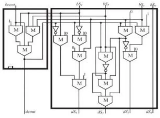
Fig. 4 Module CL and New ADD2module.
As the fundamental outcome, the proposed methodology prompts the best exchange off
between the by and large possessed region and the speed exhibitions. To comprehend the new
plan technique, given us a chance to inspect first the 4 bits paired adder ADD1. 4 bit paired adder
ADD1 gathers the estimation of information dA(3:0) and dB(3:0) and its convey "cin" and make
sense of its parallel yield as bS(3:0) and "bcout", this entire procedure it completed according to
Available online: https://edupediapublications.org/journals/index.php/IJR/ P a g e | 1404 Ci+1 = M(dAi,dBi,Ci) … . (2a)
Ci+2= M(Ci,M(dAi+1,dBi+1,gi),M(dAi+1,dBi+1,pi)) … (2b)
Subsequently, the spread of Ci through useless positions would require two fell MGs to acquire
the carryCi+2. Then again, as examined in [19] and given in (2b), by misusing the helper produce
and engender signals gi =dAi•dBi and pi =dAi•dBi, the convey Ci+2 can be processed by
spreading Ci through only one MG. Condition 1 exhibits a novel method to proliferate Ci through
two continuous piece positions that additionally presents only one MG among Ci and Ci+2 yet
keeping away from the calculation of gi and pi. As a result of Equation 1, the 4-b adder ADD1
can be acknowledged by registering the conveys as detailed in
C1 = M(dA0,dB0,cin)
C2 = G1+P1•G0+P1•P0•
Cin = M(Cin, M(dA1,dB1,dA0),M(dA1,dB1,dB0))
The BCD adder here introduced pursues the customary best dimension structure showed in Fig.5,.
As the primary outcome, the proposed methodology prompts the best exchange off between the in
general possessed zone and the speed exhibitions. To comprehend the new structure technique,
how about we look at first the 4-bit double adder ADD1. It gets the digits dA(3:0) and dB(3:0)
and the convey cin as sources of info, and registers the double outcomes bcout and bS (3:0).
Shows that, for QCA-based undulating adders, the ideal rationale structure for spreading a help Ci
through a solitary piece position is spoken to by that presents just a single MG among Ci and
Available online: https://edupediapublications.org/journals/index.php/IJR/ P a g e | 1405 Fig: 5 The Proposed n-digit BCD adder
4. SIMULATION RESULTS
4.1 WAVEFORMS
4.2 DESIGN SUMMARY
Available online: https://edupediapublications.org/journals/index.php/IJR/ P a g e | 1406
CONCLUSION
The lessened number of gates of this work offers the incredible favorable position in the decrease
of territory and furthermore the aggregate deferral. The QCA engineering is in this manner, low
zone, low postponement, basic and productive for VLSI equipment usage. It is fascinating to test
the structure of the adjusted 128-piece Novel adders.
REFERENCES
[1] C. S. Lent, P. D. Tougaw, W. Porod, and G. H. Bernestein, “Quantum cellular
automata,” Nanotechnology, vol. 4, no. 1, pp. 49–57, 1993.
[2] M. T. Niemer and P. M. Kogge, “Problems in designing with QCAs Layout =
Timing,” Int. J. Circuit Theory Appl., vol. 29, no. 1,pp. 49–62, 2001.
[3] J. Huang and F. Lombardi, Design and Test of Digital Circuits by Quantum-Dot
Cellular Automata. Norwood, MA, USA: Artech House,2007.
Available online: https://edupediapublications.org/journals/index.php/IJR/ P a g e | 1407 [6] K. Kong, Y. Shang, and R. Lu, “An optimized majority logic synthesis methology for
quantum-dot cellular automata,” IEEE Trans. Nanotechnology.vol. 9, no. 2, pp. 170–183, Mar.
2010.
[7] K. Walus, G. A. Jullien, and V. S. Dimitrov, “Computer arithmetic structures for
quantum cellular automata,” in Proc. Asilomar Conf.Sygnals, Syst. Comput., Nov. 2003, pp.
1435–1439. [1] C. S. Loaned, P. D. Tougaw, W. Porod, and G. H. Bernestein, "Quantum cell
automata," Nanotechnology, vol. 4, no. 1, pp. 49– 57, 1993.
[2] M. T. Niemer and P. M. Kogge, "Issues in planning with QCAs Layout = Timing,"
Int. J. Circuit Theory Appl., vol. 29, no. 1,pp. 49– 62, 2001.
[3] J. Huang and F. Lombardi, Design and Test of Digital Circuits by Quantum-Dot
Cellular Automata. Norwood, MA, USA: Artech House,2007.
[4] W. Liu, L. Lu, M. O'Neill, and E. E. Swartzlander, Jr., "Plan rules for quantum-spot
cell automata," in Proc. IEEE Int. Symp. Circuits Syst., May 2011, pp. 2361– 2364. [5] K. Kim,
K. Wu, and R. Karri, "Toward structuring vigorous QCA models within the sight of sneak
clamor ways," in Proc. IEEE Design, Autom. Test Eur. Conf. Display., Mar. 2005, pp. 1214–
1219.
[6] K. Kong, Y. Shang, and R. Lu, "An advanced dominant part rationale amalgamation
methology for quantum-spot cell automata," IEEE Trans. Nanotechnology.vol. 9, no. 2, pp. 170–
183, Mar. 2010.
[7] K. Walus, G. A. Jullien, and V. S. Dimitrov, "PC number-crunching structures for
quantum cell automata," in Proc. Asilomar Conf.Sygnals, Syst. Comput., Nov. 2003, pp. 1435–