Single Layer Optical-scan Voting with Fully Distributed Trust
?Aleksander Essex1, Christian Henrich2, and Urs Hengartner1
1
Cheriton School of Computer Science University of Waterloo Waterloo, ON, Canada N2L 2G1 {aessex,uhengart}@cs.uwaterloo.ca
2
Institut f¨ur Kryptographie and Sicherheit/EISS Kahrlsruhe Institute of Technology
76128 Karlsruhe, Germany [email protected]
Abstract
We present a new approach for cryptographic end-to-end verifiable optical-scan voting. Ours is the first that does not rely on a single point of trust to protect ballot secrecy whilesimultaneouslyoffering a conventional single layer ballot form and unencrypted paper trail. We present two systems following this approach. The first system uses ballots with randomized confirmation codes and a physical in-person dispute resolution procedure. The second system improves upon the first by offering an informational dispute resolution procedure and a public paper audit trail through the use of self-blanking invisible ink confirmation codes. We then present a security analysis of the improved system.
1
Introduction
Research into cryptographically “end-to-end” verifiable optical-scan voting systems has come a long way toward practicality. This progress has not come easily: academics and election administrators often struggle to agree on a vast and often orthogonal set of core system properties. Similar in spirit to Benaloh [2], we advocate thecoexistence of modern cryptographic proofs of correctness and conventional, lower-tech, methods for auditing elections. In this paper we tackle a long standing trade-off of properties in the voting literature: distributed trust versus a conventional optical-scan paper ballot form.
Typically cryptographic voting schemes allow the voter to construct a receipt of their vote enabling each voter to confirm the inclusion of their ballot in the election tally. In order to protect ballot secrecy, the association between a receipt and the corresponding (clear-text) vote must be kept hidden at all times. Many proposals have relied on trusted entities or hardware to enforce this, especially with regards to ballot printing. Other proposals distribute trust among multiple entities through the use of specialized multi layer ballot forms.
Our Proposal We consider a list of requirements for end-to-end verifiable optical scan voting that factors a diverse set of stakeholders (i.e., cryptographers, election officials, legislators, democracy groups, etc). This list is by no means exhaustive and does not encompass challenges faced by other voting methods (e.g., internet, mail-in, etc). Our list is as follows:
1. Distributed trust: No single party,includingthe ballot printer(s), gains an advantage in deducing how a voter voted or in linking a receipt to its corresponding clear-text vote. This is a vital requirement of any secret ballot election employing the receipt paradigm.
2. Single layer ballot form: A ballot is a single sheet of paper with a fixed ordercandidate list3 and the voter marks the optical scan ovalsdirectly besidetheir chosen candidate. Multi layer ballots are an artifact of crypto-graphic voting, requiring voters to re-learn how to cast a ballot. Our experience in running real-world cryptocrypto-graphic
?
An extended abstract of this paper appeared at the 3rd international conference on E-voting and Identity (VoteID 2011).
3
elections—both with single layer and with multi layer ballot forms—has indicated to us that multi layer ballots are more cumbersome for voters and more difficult to administer for election officials [15, 5, 44].
3. Human-readable paper audit trail: Pursuant to the legal requirements of many jurisdictions voting, voting intent remains plainly evident on cast ballot forms. Such an audit trail also allows for recoverability in the event of lost or forgotten cryptographic keys or other unforeseen errors.
4. Public paper audit trail: The collection of cast ballot forms (i.e., thepaper audit trail) can be made public without revealing the link between receipt and clear-text vote. A public audit paper trail may also be a legal requirement and is critical in protecting ballot secrecy during a manual recount.
In this paper we propose two novel end-to-end verifiable optical scan voting systems that meet all four of these requirements. Some of these properties have been examined in the literature, but no proposal has achieved all of them. Scantegrity achieves 2 and 3 [9, 7]. Prˆet `a Voter and Scratch & Vote achieve 2 and 4 [11, 40, 1, 45], two Punchscan variants achieve only 4 [20, 24], and each of Split-Ballot Voting, ClearVote and Kusterset al.achieve 1 and 4 [31, 37, 25]. A proposal due to Benaloh [2] achieves 2, 3, and 4. See the section on related work for additional discussion.
Contributions We present two novel systems for single layer optical-scan voting with distributed trust based respec-tively on the ballot styles used by Scantegrity [9] and Scantegrity II [7].
Basic System: We propose a basic two-party system for creating ballot forms with randomized confirmation codes that meets properties 1, 2, and 3. It relies on a private paper audit trail and an in-person physical dispute-resolution procedure.
Improved System: We then propose an improved two-party system that uses ‘self-blanking’ invisible ink confirma-tion codes. It improves on the basic system by allowing the paper audit trail to be made public, thereby achieving all four properties. In addition it offers an informational dispute-resolution procedure allowing disputes to be resolved based on knowledge of a confirmation code (as opposed to physical possession of a receipt).
2
Preliminaries
2.1 Physical Primitives
End-to-end verifiable ballots often employ physical security methods as part of the receipt creation process. The use of physical security mechanisms can be contentious due to inherent questions regarding their cost, feasibility, and real-world security properties. However, there is precedent for protocols built aroundidealphysical security mechanisms (c.f. [19, 30]). Throughout the rest of this paper we assume that all physical security mechanisms function ideally. Broadly speaking the ballot secrecy properties of our systems reduce to those of Scantegrity’s when the physical security mechanism fail.
Physical Security Mechanisms We briefly summarize the physical security mechanisms employed by our systems.
Invisible ink as its name implies is initially invisible when printed and becomes visible only afteractivation. It was proposed for use in the Scantegrity II system [7], and has been implemented and fielded in a live municipal election in the United States [5]. For the improved system presented in Section 5 we additionally make use of a ‘slow’ developing ink,
Scratch-off coating is a convenient, cost-effective and widely available method for concealing (and subsequently revealing) printed information. It has been employed in several voting schemes (cf. [1, 42]) to protect ballot secrecy,
Physical Security Sub-protocols We briefly summarize the physical security sub-protocols used by our systems.
Document Authenticity: We require a method for determining a document’s authenticity. Classical methods for anti-counterfeiting (e.g., watermarks, holographic foil, embedded magnetic strips, etc) can be cost-prohibitive. Paper fibre analysis (cf. [13]) using commercial-grade scanners is possible4. For the sake of our description we assume that there exists an efficient physical scheme for determining a ballot’s authenticity,
Private Printing: we make use of private printing techniques to pick and printhuman-readableconfirmation codes on ballots without either printer individually knowing which codes were printed. A proposal for two-party private printing was made in [16]. Private printing is used in the improved system.
2.2 Cryptographic Primitives
We briefly outline the main cryptographic primitives used by our systems. We note that these primitives are standard across the cryptographic voting literature.
Homomorphic Encryption LethDKG,Enc,DDecibe a distributed public-key encryptionscheme. Without loss of generality,DKGgenerates two private key sharesx1 andx2 for partiesP1 andP2 respectively and a joint public keyY. EncryptionJmK = EncY(m, r)is semantically secure and homomorphic in at least one operation.
Decryp-tionm = DDec(x1, x2)(JmK)requires both key shares. Specifically we will make use of exponential Elgamal [14] with distributed decryption [36]. For simplicity we will omit the public-key when implied. We additionally require a partially-homomorphic xoroperation⊕˜ such that, for a pair of messagesm1, m2∈ {0,1},Jm1K⊕˜m2produces a ci-phertext that encrypts the bitwise xor of the associated plaintext bits, i.e.,Jm1⊕m2K. We now present a bit encryption scheme based on exponential Elgamal though there is more than one way to accomplish this (cf. [22, 33]).
A Partially Homomorphic bitwise XOR with Exponential Elgamal For two bitsm1, m2 ∈ {0,1}and their as-sociated encryptions, we describe a method based on exponential Elgamal to implement apartially homomorphic operation⊕˜ for whichJm1K⊕˜m2produces a ciphertext that encrypts the bitwise xor of the associated plaintext bits, i.e.,Jm1⊕m2K.
The first party constructs a ciphertextc=hc1, c2i=hgr, gmyriform∈ {0,1}and transmitscto the second party. The second party will select their bitm0 ∈ {0,1}and compute the partially-homomorphic xor,c⊕˜m0=PHX(c, m0)
where,
PHX(c, m) =
ReRand(c) m= 0
ReRand(hc−11, g1c−21i)m= 1.
This scheme is essentially the same the inversion scheme used by Neff in [33]. Importantly, this approach alone only provides security against passive adversaries: the first party could construct a malformed ciphertext, while the second party could throw away the first party’s contribution all together. The simplest way to provide integrity would be to run a cut-and-choose protocol whereby both parties output numerous instances of hc1, c2i = PHX(c1, m2)
and conduct a coin-toss protocol to select some instances to challenge. Parties would open the challenged instances (revealing their respective message bits and random factors), and retain the unopened ones for further use.
Mixnets Mixnets have long been a fixture in cryptographic voting. We make use of a simple re-encryption mixnet (cf. [34]) structure to create our proofs (we do not utilize a separate proof of correct mixing, as it is provided by other parts of our system).Re-randomization(a.k.a., re-encryption) of a ciphertextcis accomplished by computing c0 =ReRand(c, r) = c·Enc(0, r)5. By rerandomizing and shuffling a batch of ciphertexts we implement a simple reencryption mixnet,Mix. In this paper, when applyingMixto a matrix of ciphertexts, we describe mixing as occurring ontuplesof ciphertexts grouped by columns and shuffled by rows.
4
In general there are privacy threats due to fingerprinting documents however this is not a threat to ballot secrecy assuming non-collusion.
5
Commitments We use a cryptographiccommitmentscheme to commit to permutations as part of a cut-and-choose proof of shuffle. The dispute resolution procedure in the improved system requires the prover to either unveil (i.e.,de -commit to) the code, or alternatively to issue anon-interactive proof of plaintext inequality. A commitment inherent toIND-CPAsecure encryption fits this dual role. Here a sendercommitsto a messagemby posting its encryption
JmK=Enc(m, r). Later the commitment can be unveiled when the sender reveals anm
0, r0, allowing anyone to verify
Enc(m0, r0) =JmK, and hencem
0=m. This approach is commonly used in several voting schemes (e.g., [3, 1, 43]).
Non-interactive Challenges As part of our cut-and-choose correctness proof we require a method for fairly generating random challenge bits. Loosely speaking,fairness, requires that no one is able to predict, or controllably influence the output with non-negligible advantage. Furthermore, the fairness of the method should beconvincingto voters. Both the heuristic due to Fiat and Shamir [18], and the notion of arandom beacon(cf. [39, 12]) are possibilities.
2.3 Participants
There are several entities that participate in the election.
– A set ofvoterswith the authority to cast a ballot in the election, optionally construct a privacy-preserving receipt of their vote, and optionally participate in an election audit,
– Anelection operations commissionCwith the capability and authority to organize and run an election, operate a polling place, optically scan ballots, report results, act as a custodian of the cast ballot record, and participate in an in-person dispute resolution procedure,
– Two independentballot printersP1,P2 who possess the capability and authority to print documents in the un-trusted printing model and participate in a secure (cryptographic) two-party computation,
– An electionscrutineerSwith the authority to audit the correctness of printed ballots relative to their cryptographic representation. AdditionallySacts as a proxy for voters during disputes withCto protect their identity. In practice there might be any number of election auditors, representing the candidates or other democracy groups.
As a fundamental requirement of our security model, we assume that neither printer nor election commission collude with one another.
3
The Basic System
The basic system produces a public and universally verifiable cryptographic proof attesting to the correctness of the election’s outcome. This correctness proof is based on standard cut-and-choose techniques (cf. [9, 7, 8]). Without loss of generality we consider a single-contest election involvingn ballots6 andm candidates. The basic system involves several protocols. The protocolsgenerateBallots,preElectionPrep,postElectionPrepencompass the prepa-ration for the public election audits. Note that each of these protocols taken individually is only secure in an honest-but-curioussetting. To make them robust against an active adversary we make use of a set ofauditprotocolsproveScan,
proveReceipt,provePrintingandresolveDispute. A summary of notations used is presented in Table 1.
The Ballot The basic optical-scan paper ballot form has a pre-printed, fixed-order candidate listL = {l1. . . lm}.
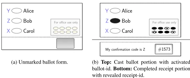
Adjacent to each candidate is an optical scan oval with amark stateµ∈ {0,1}corresponding respectively to whether the oval was unmarked or marked. The ballot form is separated into two regions by a perforation. The top constitutes theballot portion, and the bottom is thereceipt portion. An alphabetΣ ofm confirmation codes is defined. Each optical scan oval (and hence each candidate) is associated with a confirmation code drawn independently at random, and without replacement, fromΣ. Aballot-idbis ad-bit7vector printed on the ballot portion. An independent receipt-idris printed on the receipt portion. The first printer prints the receipt-ids under a scratch-off coating and the second
6
The number of ballots printed is the total number of voters times aheuristicallychosen expansion factor to account for audited and spoiled ballots.
7
n Number of ballots to print T List of all ballot-tuples m Number of candidates BallotTable Table of ballot information
d Bit-length of ballot-id ReceiptTableTable of receipt information L List of candidate names MP1/MP2 Printer 1/2’s master permutation Σ Confirmation code alphabet π/ρ Random perm’ns composing toMP1 α Soundness parameter σ/τ Random perm’ns composing toMP2 b/B Ballot-id/list of ... MidMarks Intermediate mark state list
r/RReceipt-id/list of ... MidMarksP1P1’s intermediate mark state list c/CConfirmation code/list of ... MidMarksP2P2’s intermediate mark state list
µ Mark-state of opscan oval eid Election-unique identifier Table 1: Notations
prints the confirmation codes. Both printers will jointly print the ballot-id in invisible ink. Printing of the ballot- and receipt-ids is done such that each printer only knows whatitprints (and not what its counterpart prints). The basic ballot is depicted in Figure 1(a).
Alice
Bob
Carol
Y
Z
X
For office use only
1
(a) Unmarked ballot form.
Alice
Bob
Carol
Y
Z
X
For office use only
#1573 My confirmation code is Z
1
(b) Top: Cast ballot portion with activated ballot-id.Bottom:Completed receipt portion with revealed receipt-id.
Fig. 1:Basic ballot: Optical-scan ballot form withballot portion(top) and tear-offreceipt portion(bottom) depicting a randomized confirmation code list, a unique ballot-id printed ininvisible ink visual-cryptoand a unique receipt-id beneath a scratch-off coating. Ballot printing is distributed between two printers such that neither can match receipts with cast ballots.
Ballot tuple A ballot is fully specified by the tuple{b, r, c}, which denotes the association between a uniqueballot-id bit vectorb∈ {0,1}d, a uniquereceipt-idr∈ {1. . . n}, and a random permutation ofconfirmation codesc=π(Σ)
for a permutationπdrawn independently and uniformly at random from the set of possible permutations ofΣ.
3.1 Election Preparation
The election is initialized as follows: election commissionC initializes a public bulletin board BB8 and a unique election identifiereid. PrintersP1andP2jointly runDKG. They post the public keyY to public bulletin boardBBand retain their respective private key sharesx1, x2. This list of public parameterspubParam={n, m, d, L, Σ, α, eid, Y} is posted toBB. All functions/protocols acceptpubParamas input.
8
Ballot Tuple Creation The printers now jointly generate encrypted ballot tuples by runninggenerateBallots. This protocol is given in Algorithm 1.
Algorithm 1:generateBallots
Participants: PrintersP1,P2 PrinterP1should:
1
fori∈ {1. . . n}do 2
Encrypt vectors of random bits:
3
B0(i)←(Enc(randBit), . . . ,Enc(randBit))
4
Post a non-malleable commitment to eachrandBitalong with the random factor used to encrypt it.
5
Encrypt and shuffle receipt-ids:
6
R←Shuffle(Enc(1). . .Enc(n))
7
end 8
PrinterP2should: 9
fori∈ {1. . . n}do 10
Randomly shuffle and encrypt code confirmation codes:
11
C(i)←Shuffle(Enc(Σ(1)). . .Enc(Σ(m)))
12
end 13
Both Printers should: 14
Simultaneously and respectively outputB0,RandCtoBB.
15 end 16
PrinterP2should: 17
fori∈ {1. . . n};j∈ {1. . . d}do 18
Homomorphically xor random bits:
19
b01. . . b 0 d←B
0
(i)
20
B(i)←(b01⊕˜ randBit, . . . , b0d⊕˜ randBit)
21
Post a non-malleable commitment to eachrandBitalong with the random factor used in computing the xor.
22
OutputBtoP1 23
end 24
//Remark:Shuffle(X)applies a permutation to a listX, drawn independently and uniformly randomly from the set of permutations of size|X|.randBitreturns a single bit drawn independently and uniformly at random. It is possible that P2might attempt to maliciously select its bits as a function ofP1’s. HoweverP2will not know (beyond a guess) what to
print on the ballot, and will be caught inProvePrintingwith statistical certainty.
Ballot Printing Thenballot forms are printed in three steps. For each ballot-tuple a paper ballot is prepared in the following order:
– Static background:directions, candidate names, etc, printed in black ink,
– P1’s share:the receipt-id is printed and concealed under scratch-off coating,P1’s share of the ballot-id printed in invisible ink visual-crypto,
– P1’s share:the confirmation codes are printed in regular ink,P2’s share of the ballot-id printed in invisible ink visual-crypto overP1’s share.
Pre-Election Proof Preparation The printers initialize the public audit dataset and cut-and-choose correctness proofs by runningpreElectionPrep. This protocol is given in Algorithm 2.
Voting and Receipt Creation An individual wishing to vote shall attend the polling place and authenticate themselves toC. All qualified and authenticated individuals (i.e., voters) are then eligible to receive a ballot. The voter selects a ballot form at random from a stack of unmarked ballot forms and takes it, a regular (black) marking pen, and a privacy sleeve into a private voting booth. The voter marks the oval next to their preferred candidatelion the ballot
portion. Then, if they so choose, the voter creates a receipt of their vote by noting the code letterciand writes it in
the appropriate space on the receipt portion. The voter then places the marked ballot form into the privacy sleeve and returns it to the poll worker. The poll worker confirms the receipt-id’s scratch-off coating is still intact and the ballot-id has not been activated (rejecting the ballot in such a case), then detaches the receipt portion and places it on a table in view of the voter. The ballot portion is then fed into the optical scanner. If the ballot is accepted the receipt portion is retained by the poll worker. If the ballot portion is successfully cast, the receipt portion is returned to the voter and the voting process is complete. A diagram showing completed ballot and receipt portions is depicted in Figure 1(b).
A Note about Timing Attacks In some jurisdictions, poll workers keep a poll book of voter identities in theorder they voted. If the scanner were to likewise maintain the order of cast ballots it, taken along with the poll book, would compromise ballot secrecy. Since in our case the ballot is drawn at random from the pile, and the poll worker does not see the ballot- or receipt-ids, this threat can be mitigated by having voters cast ballots into a ballot box at the polling place and then scanning them later at a central location.
Post-Election Proof Preparation After the electionC populates the BallotTablewith the mark state information collected by the optical scanners. With this data the printers and can now finalize the cut-and-choose correctness proof by runningpostElectionPrep. This protocol is given in Algorithm 3.
4
Verifying the election
4.1 Election Audits
There are three simultaneous properties that must be proven in order for the overall results to be proven correct. These audits include,
– Proving correct mark-state reporting byC: Using their receipt, a voterVchecks whetherCcorrectly registered their vote by runningproveScan,
– Proving mark-state propagation byP1,P2: The printers prove to any interested party that they honestly applied their master permutations to mark state information inBallotTableby runningproveReceipt,
– Proving printed ballot forms matchBB: A scrutineerS9runsprovePrintingwith the printers to verify that the ballot tuple information conveyed by the paper ballot formsmatchesthe ballot tuple representation inBB. Audited ballots arespoiledand not counted.
The audit protocolsproveScan,provePrintingandproveReceiptemployed by the basic scheme are below in listed in Algorithms 4, 5 and 6 respectively.
4.2 Dispute Resolution
Because the receipt generation process is unsupervised, a number of possibilities for disputes may arise between the bulletin board and the voters. A simple dispute resolution procedure was proposed for Scantegrity I in [9]. Briefly, this involved a two-stage physical protocol using special privacy sleeves.
9
Algorithm 2:preElectionPrep
Participants: PrintersP1,P2 Public Input: Candidate listL
Private Input: Lists of encrypted ballot-idsB, receipt-idsR, and code shufflesC Both Printers should:
1
//Expand thenballot tuples into a table ofmnrows (one for every candidate on every ballot):
fori∈ {0. . . n−1}do 2
c1. . . cm←C(i)
3
for0≤j≤m−1do 4
T(1, mi+j)←B(i)
5
T(2, mi+j)←Enc(L(j+ 1))
6
T(3, mi+j)←R(i)
7
T(4, mi+j)←cj
8
//P1followed byP2using master permutationsMP1andMP2respectively: T0←Mix(T)
9
//Create ballot and receipt tables: BallotTable←DDec(T0(1. . .2,:))
10
ReceiptTable←DDec(Mix(T0(3. . .4,:))
11
PostBallotTable,ReceiptTabletoBB
12
end 13
//Prepare cut-and-choose proof of correspondence between elements in the ballot and receipt tables:
PrinterP1should: 14
fori∈ {1. . . α}do 15
Chooseπi∈RΠmn
16
Setρisuch thatρi◦πi=MP1 17
PostCommit(πi),Commit(ρi)toBB
18
end 19
PrinterP2should: 20
fori∈ {1. . . α}do 21
Chooseσi∈RΠmn
22
Setτisuch thatτi◦σi=MP2 23
PostCommit(σi),Commit(τi)toBB
24
end 25
//Remark: Letx∈rΠydenote a permutation functionxdrawn independently and uniformly at random from the set of
Algorithm 3:postElectionPrep
Participants: Election CommissionC, PrintersP1,P2
Private Input: Secret Master permutationsMP1,MP2, Scanned Cast Ballots //PopulateBallotTablewith scanner data
Election commissionCshould: 1
foreach{b, s, µ}recorded by scannerdo 2
Findifor whichballotTable(1, i) =b 3
andballotTable(2, i) =s 4
ballotTable(3, i)←µ 5
PostballotTable(3,:)toBB.
6 end 7
//Propagate marks fromBallotTabletoReceiptTable
PrinterP1should: 8
MidMarks←MP1(BallotTable(3,:)) 9
PostMidMarkstoBB fori∈ {1. . . α}do 10
MidMarksP1i←πi(BallotTable(3,:))
11
PostMidMarksP1itoBB
12
end 13
PrinterP2should: 14
ReceiptTable(3,:)←MP2(MidMarks) 15
PostReceiptTable(3,:)toBB. fori∈ {1. . . α}do 16
MidMarksP2i←σi(MidMarks)
17
PostMidMarksP2itoBB
18
end 19
Background Initially the election commissionCdemonstrates to the voter that their ballot portion is present in a set of ballot portions as follows:
– Cretrieves the voter’s ballot portion and gathers additional ballot portions such that theyallshow a mark beside an oval showing the voter’s asserted code, but each in a different position. The voter checks that all the ballot portions indicate a mark for the same code letter therefore suggesting what the ballot’s entry in the receipt table should be—if one of those ballot portions matches the receipt portion. Because the ballot portions each register a vote for different candidates, any other entity present for this procedure will not know how the voter voted. – C places each of these ballot portions into a separate privacy sleeve that hides everything except the bottom
perforation line. The ballots are shuffled.Cthen demonstrates to the voter that the paper fibre pattern of the receipt physically matchesone ofthe ballot portions in the set. This proves that the ballot portion the voter cast is present in the group.
The two steps taken together prove which code the voter marked. The downside of this approach, of course, is that Cmust know the association between the receipt portion and ballot portion (and therefore between receipt and vote) in order to perform dispute resolution.
The procedure We now describe the dispute resolution procedure for the basic scheme presented in Section 3. In order to conceal the identity of the voter fromC(who has their ballot) we assume there exists a scrutineerSthat will function as a proxy for the voter during the procedure. Note that the voter will have to trust theS to honestly follow the protocol.
Note howeverSdoes not learn how the voter voted. The dispute resolution procedure for thebasic schemeis as follows:
2. P1finds the row inRthat contains the encryptionrand transmits this indexitoP2, 3. P1andP2each (privately) send toCthe bit vectors they used to constructB(i),
4. Ccomputes the bitwise xor of the received bit vectors and locates the ballot portion with the resultant ballot-id, 5. Splaces their receipt portion in a privacy sleeve that hides the receipt-id,
6. SandCcontinue with the Scantegrity dispute resolution procedure as defined in [9].
A possible dilemma In many cases the voter will be found to have made a transcription error. However a major dilemma arises from this procedure when it is that case thatChas misreported the code: the voter must give up ballot secrecy to prove to the public thatCis in error.
One of our fundamental requirements for ballot secrecy is that no one be permitted to know the association between ballot-id and receipt-id. If the voter wrote down their code incorrectly, this is not a problem:Ccan prove it without needing to know the receipt-id. However ifCreported the code incorrectly, then the receipt-id would need to be made public to prove the discrepancy between the physical and electronic records. This violates ballot secrecy as we have defined it. Still, in the case that the ballot-id/receipt-id association needs to be revealed, it may still suffice if the association betweenvoter identityand receipt-id is suppressed. This however would essentially require the voter to never show their receipt to anyone. We leave solving this dilemma to future work, noting that it is mooted by the use of an informational dispute resolution process. We now present an improved system with such an informational dispute resolution procedure.
5
Improved System
In this section we present a system that improves upon the basic system in two ways: First, it replaces the physical dispute resolution procedure with aninformationaldispute procedure. Second, the collection of cast ballots (i.e., the paper audit trail) can be viewed publicly without compromising ballot secrecy.
Informational Dispute Resolution The dispute resolution procedure of the basic system is inefficient and time con-suming. Chaum et al. proposed the notion of invisible ink confirmation codes in Scantegrity II [7] as aninformational means of resolving dispute. Under this approach, codes are printed in invisible ink, and only revealed to the voter if marked. Assuming the code space is sufficiently large so as to make successful random guess unlikely, then knowl-edge ofanyvalid code can be taken as evidence that a voter correctly created their receipt. Any discrepancy found between a receipt and theReceiptTablecan then be attributed toC(assuming the other correctness proofs are valid). In the improved system, we create and print the codes using aprivate printingprotocol. Thus the role of invisible ink is twofold: it restricts the voter’s knowledge of unmarked codesand it prevents the printers from linking receipts to votes.
Algorithm 4:proveScan
Participants: Any voterVwho created a receipt Public Input:ReceiptTable,V’s receipt{r, cv} //Check receipt againstReceiptTable:
VoterVshould: 1
Find rowifor whichReceiptTable(1, i) =r 2
andReceiptTable(2, i) =cv
3
ifReceiptTable(3, i)= 1then 4
ACCEPT 5
else 6
RunresolveDispute 7
Algorithm 5:proveReceipt
Participants: PrintersP1,P2and any interested party Public Input: A vectorChallengeofαchallenge bits. Both Printers should:
1
fori∈ {1. . . α}do 2
ifChallenge(i) = 0then 3
P1unveils commitment toπi
4
P2unveils commitment toσi
5
ifChallenge(i) = 1then 6
P1unveils commitment toρi
7
P2unveils commitment toτi
8
All decommitment information is posted toBB.
9
end 10
Anyone can: 11
RunverifyCommiton all of the unveiled commitments
12
fori∈ {1. . . α}do 13
ifChallenge(i) = 0then 14
Check:πi(BallotTable(3,:)) =MidMarksP1i
15
Check:σi(MidMarksP2i) =ReceiptTable(3,:)
16
ifChallenge(i) = 1then 17
Check:ρi(MidMarksP1i) =MidMarks
18
Check:τi(MidMarks) =MidMarksP2i
19
end 20
//Remark:Challengeis generated by a public coin toss, or the Fiat-Shamir heuristic when appropriate (e.g., forα >80.)
Public Paper Trail Invisible ink confirmation codes require a code space that makes random guessing statistically unlikely. For example Scantegrity II proposes a 3-digit code (making a random guess successful 0.1% of the time on average). However in the presence of unique (or semi-unique) codes, access to cast ballots coupled with the public audit dataset is sufficient (or nearly sufficient) to allowanyobserver to link receipts to clear-text votes. This not only means that the paper ballot record must be keptsecret, but further that the custodian of the ballot record (i.e.,C) is trusted with knowledge of how voters voted. This is one of the major limitations of Scantegrity II. To address this privacy weak-spot, we require a method for not only privately printing a confirmation code, but for displaying itonly while the voter is in the booth. In the presence of “disappearing” codes, not only can we offer distributed trust with respect toP1,P2andC, but we can also make the paper ballot record public.
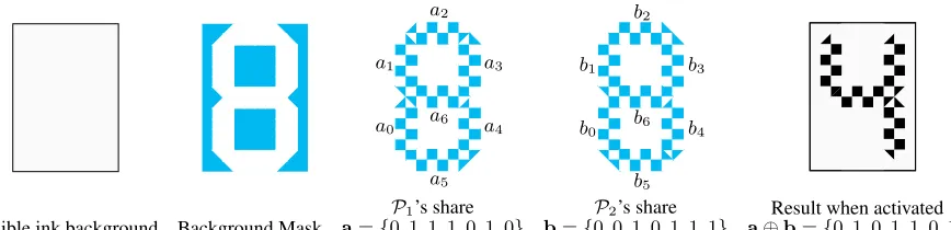
Self-blanking Confirmation Codes We propose a method for printing of confirmation codes that is self-blanking (i.e., the message is only temporarily visible). The standard invisible ink described by Scantegrity II activates in-stantaneously. That is to say, the chemical reaction responsible for the ink’s pigmentation completes on the order of milliseconds. It was suggested in [7] that aslowerreacting ink might by the addition of ananti-catalyst. This sub-stance, if present, can slow down pigmentation by seconds or minutes (depending on design needs). Combining the technique of visual cryptography with such a ‘slow’ invisible ink, we can construct a self-blanking pixel (see Table 2). Finally, combining self-blanking pixels with the private printing protocol of [16], we can print confirmation codes that are both distributed between two-parties and self-blanking.
Algorithm 6:provePrinting
Participants: PrintersP1,P2, ScruitineerS
Public Input: A printed ballot chosen at random byS
ScrutineerSshould: 1
Activate/scratch-off hidden areas on ballot form to reveal ballot tuple
2
Post ballot tuple{b, L, r, c}toBB
3
end 4
PrinterP1should: 5
foreachBallotTable(1, i) =bdo 6
Unveil the commitments toP1’s share ofb(i.e., ballot id bits and associated random factors). 7
foreachj∈ {1. . . α}do 8
Postiπj ←πj(i)
9
Postiρj ←ρj(iπj)
10
end 11
PrinterP2should: 12
foreachiρj do
13
Unveil the commitments toP2’s share ofb(i.e., ballot id bits and associated random factors used to compute the 14
xor withP1’s share). foreachj∈ {1. . . α}do 15
Postiσj ←σj(iρj)
16
Postiτj ←τj(iσj)
17
end 18
Anyone can: 19
RunverifyCommiton all of the unveiled commitments,
20
Recompute ballot-idbusing the unveiled id bits and associated random factors and ensure it matches both the electronic
21
and printed versions,
foreachBallotTable(1, i) =bdo 22
foreachj∈ {1. . . α}do 23
Output an error and exit if the following does not hold:,
24
BallotTable(3, i) =MidMarksP1j(iπj) =MidMarks(iρj) =MidMarksP2j(iρj) =ReceiptTable(3, iτj)
25
Output 1
26
end 27
Result when activated a bVC(a)VC(b) t= 0t >0 t >>0
0 0 ∅ ∅
0 1 ∅ ∅
1 0 ∅ ∅
1 1 ∅ ∅
Table 2:Self-blanking VC Pixel. Two sub-pixels contain invisible ink. Each party applies an anti-catalyst (cyan) to onesub-pixel. Sub-pixels containing this substance darken more slowly than those without (t = 0is the moment of activation). Eventually all sub-pixels darken “blanking” the pixel’s value.
Changes to the protocols The addition of self-blanking invisible-ink confirmation codes induces some changes the protocols presented in Section 3 which is summarized as follows:
1
(a)t= 0
1
(b)t >0
1
(c)t >>0
Fig. 2:Optical-scan oval with self-blanking confirmation codeafter being marked with an activator pen (t = 0is the moment of activation).
– Ballot printing:P2 prints ballot-ids in invisible ink. Both printers print their shares of the confirmation codes using self-blanking visual crypto pixels,
– Informational dispute resolution: As in Scantegrity II, the printers only publish the confirmation code corre-sponding to the voted candidate. In the case of a dispute, the printers jointly issue a non-interactive proof of plaintext inequality between all remaining (unencrypted) codes on the disputed ballot.
5.1 Changes togenerateBallots
ThegenerateBallotsalgorithm of the basic system is adjusted as follows:P1is still responsible for generating and printing a list of unique receipt-idsR.P2nowsolelygenerates and prints the ballot-idsB. Both printers collaborate to privately generate and print the confirmation codesC. This is accomplished by aprivate printingprotocol to select a confirmation code and distribute it to visual crypto shares.
For each confirmation code, the printers engage in the following pre-protocol. We briefly sketch how this is accom-plished, referring the reader to [16] for a concrete example. First the printers run a two-party (dealerless) protocol to privately select a single message (i.e., confirmation code) from a set of valid messages, distribute the message to visual crypto shares, and privately output each share to the respective printer. Using these resultant bit-vectors as private input togenerateBallots, they homomorphically xor their shares together, repeating for each candidate across each ballot to create confirmation code listC. To make the protocol more efficient, the confirmation code digits can be represented by a 7-segment display, allowing each digit to be represented by 7-bits (and hence 7 ciphertexts).
5.2 Changes to ballot printing
As in the basic ballot,P1prints the receipt-idsR(i)and conceals them under scratch-off coating. For each optical-scan bubble,P1 applies a solid background of invisible ink and overlays its visual crypto share using the inhibitor substance. Maintaining the ordering,P1transfers the ballots toP2, who prints the ballot-idsB(i)in invisible ink (n.b., without visual crypto). It then applies its VC shares to the corresponding optical-scan bubbles. Printing self-blanking confirmation codes is depicted in Table 3.
Changes topreElectionPrep For the most part, the improved system has the same overall structure in terms of the cut-and-choose proof. ThepreElectionPrepis executed in the same way, obviously with the minor difference that the elements of ballot-id listB are now single ciphertexts (as opposed lists ofdencrypted bits), and the elements of receipt-id list Rare now encrypted as bit-vectors. WhenReceiptTable is generated, the receipt-ids are decoded from their 7-segement bit-vector representation into a single integer. However beforeReceiptTableis posted toBB, the printers willencrypteach of the confirmation codes (now in integer form) to facilitate the informational dispute resolution procedure. They will save the random factors used in these encryptions for later use.
Invisible ink background Background Mask a0 a1
a2
a3
a4
a5 a6
a={0,1,1,1,0,1,0}
P1’s share
b0 b1
b2
b3
b4
b5 b6
b={0,0,1,0,1,1,1}
P2’s share
a⊕Result when activatedb={0,1,0,1,1,0,1}
Table 3:Printing a self-blanking invisible ink confirmation code:P1andP2 run a two-party protocol to select a code and distribute it to VC shares (a,brespectively). They respectively apply an anti-catalyst (cyan) over a solid invisible ink background. When activated the code becomes temporally visible (eventually darkening to all black).
Changes toprovePrinting WhenAaudits the printing of a ballot, the codes will only be temporarily visible after activation. This is problematic shouldAneed to use the ballot as evidence in the event ofprovePrintingfails. There are several ways this might be addressed. One way would be forAto take a photograph or video of the activated codes however this may not constitute strong enough evidence. Another way would be to require multiple independent auditors to be present when revealing codes. The evidence then would be the testimony of (honest) auditors which may be problematic if a dispute arises over which codes were observed. Finally, we could conjecture the existence of a “fixer” chemical that could halt (or slow) the reaction. This could potentially be accomplished by applying high concentrations of the anti-catalyst substance immediately after activation.
Changes to the dispute resolution procedure The voter can file a dispute by submitting their receipt-idrand the confirmation codecvthey claimed to have seen. Recall in Scantegrity II,Cresponds by unveiling all the commitments
to confirmation codes on the dispute ballot ballot. This is acceptable within their security assumptions since C is trusted to protect ballot secrecy. However since in our systemCis untrusted, the printers must prove inzero-knowledge that the disputed code isnot equalto any of the encrypted codes inReceiptTable, and nothing more. Ifcvis a valid
confirmation code of receipt-idr, the printers prove the decryption of the associated code inReceiptTable. Ifcv is
nota valid confirmation code, for each rowifor whichReceiptTable(1,:) =r, the printers (jointly acting as a single prover) issue a non-interactiveproof of plaintext inequality betweenReceiptTable(2, i)andcv. An algorithm for a
proof of plaintext inequality,plaintextInequalityProof, is given in Algorithm 7.
6
Security Analysis of the Improved System
To briefly summarize our results, owing to the similarities between systems, we reduce the correctness of the improved system to that of Scantegrity II [7]. Although Scantegrity has been peer reviewed and used in a real election we are not aware of a formal proof of the correctness. A formal security proof for the improved system would include a formal security proof for Scantegrity II and is out of the scope for this paper. A proof of correctness of Eperio, a related system, does offer some insight into how such a proof would proceed [17]. With respect to secrecy we present an argument that the improved system protects voter privacy even when one printer is corrupted. Assumptions regarding the physical primitives can be found there as well.
6.1 Assumptions
Algorithm 7:plaintextIneqalityProof
Participants: PrintersP1,P2acting as a single proverP, VoterV
Public Input: An asserted confirmation codem0, a encrypted confirmation codec=E(m), public keyhg, q, y=gski
ProverPshould: 1
//Encrypt asserted codem0 Posthc1, c2i=hgr, myri
2
//Blind quotient ofm/m0
Selectb∈rGqand postc0=hc01, c20i=h(c1)b,(mc20) bi
3
//Prove knowledge ofb
Post proof of conjunction onDDH-tuplehc1,c2
m0, c 0 1, c02i 4
//Post decryption ofc0 Posthrb,(mm0)bi=hu, vi 5
end 6
VerifierVshould: 7
Verify proof knowledge ofbin step 4
8
Verify decryption ofc0:hgu, vyui=hc01, c02i 9
Verify plaintext inequality ofm, m0:v6= 1
10
Output 0 and exit if any the above do not hold, otherwise output 1.
11
end 12
//Remark: This is essentially the plaintext equality test due to Jakobsson and Jules [21] adapted for a single prover. A proof of conjunction ofDDH-tuples is due to Chaum and Pedersen [10].
Tamper Evidence Although scratch-off coating and invisible ink function as a form ofphysical commitmentscheme, they do not offer the strong assumptions that govern the unveiling of a cryptographic commitment scheme since anyonecan open such a physical commitment. We make use oftamper evidencein the physical commitment setting as a weaker alternative to the hiding property of a cryptographic commitment (cf. [30]). Instead of thehidingproperty of cryptographic commitment, a physical commitment ideally has the property that an adversary must activelytamper with a document to reveal its secret, which then will beevidentto the intended recipient.
Scratch-Off Coating We use scratch-off coating to reversibly conceal some information printed onto a ballot. First we assume that such coating is secure under passive attack, i.e., the message cannot be read without actively tampering with the coating. However anyone can easily remove the coating, so instead of a hiding property we make theideal assumptionthat revealing the information under the coating canonlybe done in a way that it isevident. By checking the integrity of the scratch-off coating anyone can reliably decide whether or not the physical commitment was opened before. If the coating is intact, anyone can be convinced that the content of the commitment is still hidden. In the presence of tamper evidence this type of physical commitment can viewed asbindingin the sense that modifying the underlying message would require tampering.
Invisible ink For the use of invisible ink we make similar ideal security assumptions as for scratch-off coating with regards to security to passive attack and tamper evidence in the case of active attack. In contrast to scratch-off coating however, it is possible, and actuallydesirable, to be able to add (but not remove) printed information.
6.2 Correctness
For the proof of correctness we assume both the voting authority of Scantegrity II, as well as the election commis-sion and both printers of the improved system, are corrupted and under the complete control of an adversaryA. For simplicity we combine the election comitteeC and printersP1 andP2 and denote it asC. Note that in this caseC knows everything printed in invisible ink or under a scratch-off coating and the physical assumptions only prevent uncorrupted voters from learning information protected that way. We further assume that both voting systems use the same commitment scheme.
Assume there exists an adversaryAable to undetectably cheat in an election run using our improved system. We show how this adversary can then be used to undetectably cheat in a Scantegrity II election by giving a translation fromAto an attack on Scantegrity II. LetE = {C,V1. . .Vn}be an election system with election commiteeCand
votersV1. . .Vn. We say an election system is sound, if, for all adversariesA, the probability of a verifier accepting an
invalid correctness proof is negligible in the security parameter.
Technique Toward a contradiction, we will show how to use the existence ofA, which implements a correctness attack on our system, to leverage the equivalent attack on the Scantegrity II system. We will accomplish this with rewindable black-box access toA. At a high-level, we translate an election being run with Scantegrity II into an election being run with our system. At each phase of the election, we receive output fromAand translate it into the equivalent output in Scantegrity II. We are essentially generating the equivalent election in both systems in parallel. Of course, by using A, the tally in our system is undetectably incorrect. We show how to translate this into an undetectably incorrect tally in Scantegrity II. Since this should not be possible if Scantegrity II provides correctness, it must be the case thatA cannot exist.
Reduction We generate the public parameters of the Scantegrity II election, translate them into PubParam, and initialize Awith them. This is a direct translation. We then take the output ofpreElectionPrepas generated byA and attempt to translate it back into the preelection data for Scantegrity II. This translation is possible to do directly but for convenience we will extract, via rewindingA, the permutationsπ,ρ,σandτ, which are the permutations betweenBallotTableandReceiptTable. For the extraction to work, we simulate two successful elections to request two different openings of the cut and choose proof for the correctness of the permutation. As it is a 1-out-of-2 proof this is enough to learn the permutations. With this knowledge we prepare the public information for the Scantegrity II election as follows:
Employing the similarities betweenBallotTablein our system and theStable of Scantegrity II, we initially group all rows inBallotTablewith identical ballot-ids, then remove the ballot-id column. This corresponds to the Scant-egrity IIStable. Let this mapping be calledMS. Next we mapReceiptTableto the equivalent Qtable. These two
tables are identical except we relabel receipt-ids inReceiptTableas “ballot-ids” in theQtable. Let this mapping be MQ.
Under the assumption that both systems use the same commitment scheme, we directly transfer all commitments as-is. From the permutations extracted fromAand the mappingsMQandMS we compute the mapping that maps
each cell in tableQto one in tableS.
We do this by composing{ρ, τ}and preparingQ-pointers that correspond to this resultant permutation. Similarly we generate theS-pointers from the composition of{π, σ}. Then we publish the tablesQ,RandS.
During the election phase Ahas access to ballot choices made by each voter and returns a confirmation code together with the receipt-id to the voter.
After the election phase we queryAfor the mark positions inBallotTableandReceiptTable. UsingMQandMS
6.3 Voter Privacy (Sketch)
For space considerations we only sketch the properties of voter privacy. One aspect of our improved system is that voter privacy is still guaranteed if one printer is corrupted. We claim that the additional information an adversaryA gains by corrupting one printer is insufficient to learn anything about the choice of a single voter.
AcorruptsP1 WhenAcorruptsP1 the additional information gained is the secret keyx1, a share of each code and for eachi∈ {1. . . α}the two permutationsπiandρi. AlsoAlearns all corresponding receipt-ids. The security
properties of the encryption scheme prevent Afrom decrypting any ciphertexts by only knowing x1. During the postelection proof only one ofσiorτiis ever revealed, thereforeAdoes not learn the master permutation ofP2. Thus
no information is revealed about the permutation betweenBallotTableandReceiptTablegiven that the commitment scheme is hiding. BecauseP1prints its share of ballot tuples first, it does not learn anything aboutP2’s share, which in turn ensuresAlearns nothing about the association betweenBallotTableandReceiptTable.
AcorruptsP2 WhenAcorruptsP2the additional information gained is the secret keyx2, a share of each code and for eachi∈ {1. . . α}the two permutationsσiandτi. For the same reasons as above this does not giveAan advantage
in breaking voter privacy. BecauseP1printed the receipt-id and covered it in scratch-off coating, and printed its share of the confirmation codes in invisible ink,A learns nothing about the association between receipt-ids, codes, and ballot-ids assuming the security properties of these physical primitives as stated in previous sections.
If P2 is able to read the receipt-ids (by breaking the security assumption about the scratch-off coating), or the shares ofP1(by breaking the security assumptions about invisible ink), or is even able to replace the ballots printed by P1without leaving evidence,P2learns enough to break voter privacy. In this case the privacy of the improved system reduces to that of Scantegrity II with a corrupted printer.
AcoercesV WhenAcoercesV, we seek assurance thatV cannot prove how he/she voted toA. This property is known as coercion resistance. It has been shown by K¨usters et al. that Scantegrity II achieves coercion resistance [26]. We do not attempt to prove coercion resistance for our system but given the demonstrated similarities between both the cryptography and the ballot, we would expect a proof of coercion resistance would be easy to construct following their result.
We have to assume that Adoes not have unlimited access to the public paper trail. SpecificallyAmust not be able to recognize any ballot, for example by making an in-depth analysis of the fibre structure as used for ensuring document authenticity. IfAis able to identify a ballot and has made a similar fibre analysis while the ballots were in the custody of a corrupted printerAwould be able to pair a receipt of a coerced voter with the retained part of the ballot in the public paper trail. This problem is not specific to our improved system but always occurs whenA gains enough information to link a paper receipt to a plaintext ballot in the public paper trail. A simple countermeasure would be to restrict the access to the public paper trail (not that this would have to prevent anyone from even scanning them).
7
Related Work
We review some work related to verifiable voting systems with optical-scan paper ballots. This literature can be roughly separated into two categories: systems using single layer ballot forms but reliant on trusted parties/hardware and systems with distributed trust but with multi layer ballot forms.
proofs are usually described as a multi-party computation, ballot forms are generated by a trusted printer. Cast ballots are generally “encrypted” though variants exist that leave a human readable paper trail [29, 17]. Benaloh [2] proposes that receipts be generated and printed by a special-purpose device connected to the optical scanner. This has the distinct advantage that the ballots contain no identifying information (beyond the vote). However the issue of trusted ballot printing instead becomes a matter of trusted receipt printing.
Distributed trust with multi layer ballot forms Kubiak [24] and Carback et al. [20] proposemostlydistributed modifications of the Punchscan system [38]. The former still relies on a trusted ballot printer, the later distributes printing but still relies on trusted hardware to generate ballot tuples. Carback and Popoveniuc [37] later propose a three-party distributed version of Punchscan in which top- middle- and bottom-sheet permutations are each generated by independent printing authorities. In all cases voters must use an indirect marking procedure. Moran and Naor [31] propose an improved multi layer ballot form that does not rely on indirection and with considerably stronger, provable, security properties. Voters are issued layers in separate sealed envelopes. Once inside the booth the voters are directed to remove each layers from its envelope and stack the layers in a particular order. The resultant candidate list is horizontally offset from the optical scan ovals by a randomized amount. Lundin et al. [28] propose a distributed construction of the Prˆet-`a-Voter ballot based on a form of dealerless 2-party visual cryptography. The voter must be careful to align the VC shares in the booth in order to reconstruct the candidate list. Most recently K¨usters et al. [25] present a version of Prˆet-`a-Voter system without a trusted printer, physically implementing a re-encryption mixnet using scratch-off coatings. The voter receives a separate ballot foreachcandidate, which can be cumbersome for races involving more than a few candidates.
Other schemes Chaum proposed the first physical receipt based voting system in [6]. It consists of two visual crypto layers showing the name of the voted candidate. A receipt is created by separating the layers and destroying one of them. Paul et al. [35] propose visual crypto for use in voter authentication for (non-cryptographic) remote voting systems. Scratch & Vote [1], Scratch, Click & Vote [27] and Pretty Good Democracy [41] make use of scratch-off coating to conceal encryption random factors and confirmation codes. Finally, Kelsey et al. [23] propose a voter-coercion strategy involving the use of scratch-off cards to direct voter action.
8
Discussion
8.1 Technical Challenges
The formulation of invisible inks has many areas for improvement. Although Carback et al. [5] report progress in the manufacture of invisible inks, they observed their ink chemistry led to rapid degradation in the print-heads causing printers to eventually fail after printing only a fraction of a single precinct’s worth of ballots. It also seems possible that codes could be passively attacked (i.e., read without activation) under laboratory-based forensic analysis. It would be important to the credibility of invisible ink to have a sense of how costly this would be.
Proper alignment (i.e., registration) of shares has long been a limitation of visual cryptography. Assuming an optical scan oval width of1 cm and the visual crypto pattern depicted in Figure 2, the sub pixels would be on the order of 0.3cm wide. Assuming a quality tolerance of>90%overlap of subpixels between shares, then the printing alignment would require a tolerance on the order of about3mm (in both horizontal and vertical axes). It seems plausible current consumer printers could achieve this. Printing confirmation codes in the improved scheme would require finer granularity. A rough estimate based on the codes in [5] suggests one VC sub-pixel per millimetre might suffice. This would require a precision on the order of100µm which likely exceeds the capability of consumer printing technology. We envision a device that couldsimultaneouslyscan positional markers on the document and align the print head relative to them in real-time. The authors are not aware of any existing implementation of this, but note it may be an interesting avenue for future work.
8.2 Usability Questions
Perhaps the most important question would be to understand how disappearing in might interfere with the voter marking the ballot as intended. It is certainly possible that the voter’s mental model of marking a ballot may be affected by the delayed darkening of the oval. Would this delay represent confusing feedback for the voter while they attempt to confirm whether they successfullymarked the ballot as they had intended to?
Another important question pertains to the potential pitfall to privacy if the voter leaves the booth too early. The voter would need to be instructed to stay in the booth until the oval has darkened fully (and hence the code has disappeared). The longer it takes for an oval to darken, the more likely it would be that a voter might choose to disregard the instruction and leave the booth anyway. A na¨ıve technical solution would be to dilute the inhibiting substance to speed up the reaction. However this comes at cost of giving the voter a smaller window of opportunity to write down the code on their receipt. This might especially be problematic for multi contest ballots if the voter decides to complete marking the ballot first andthenrecords their codes later, as the codes may have disappeared by then.
8.3 Future Work: Toward a Secure Multi-party Protocol
The systems described in this paper are both two-party protocols. Ultimately however it would be desirable to be able to distribute trust among arbitrarily many printers. With some modification the improved system presented in Section 5 could likely be extended to a secure multi-party protocol. With regard to creating the audit dataset this would be mostly a straightforward extension of the two-party approach with each of then > 2 printers generating their own master permutations and issuing their own cut-and-choose proofs. Generating ballot tuples in a multi-party setting should also be a fairly straightforward extension of the two-party setting.
The primary challenge will be to develop an effective approach to distribute the ballot printing among more than printers. This will undoubtedly require a fundamentally different approach from the two-party private printing scheme presented in [16] and is an interesting potential direction for future work.
Conclusion
In this paper we presented two systems for verifiable optical-scan voting with single layer ballots and without trusted components. The basic system based on randomized confirmation codes utilizes existing techniques for invisible ink printing. The improved system proposes a novel self-blanking invisible ink, allowing us to construct a system with more efficient dispute resolution procedure and public paper audit trail.
Acknowledgements
Bibliography
[1] Ben Adida and Ronald L. Rivest. Scratch & vote: self-contained paper-based cryptographic voting. In ACM WPES, pages 29–40, 2006.
[2] J. Benaloh. Administrative and public verifiability: Can we have both? InEVT, 2008. [3] Josh Benaloh. Ballot casting assurance via voter-initiated poll station auditing. InEVT, 2007.
[4] Josh D. Benaloh (n´eCohen) and Michael J. Fisher. A robust and verifiable cryptographically secure election scheme. InSFCS, 1985.
[5] Richard T Carback, David Chaum, Jeremy Clark, John Conway, Aleksander Essex, Paul S. Hernson, Travis Mayberry, Stefan Popoveniuc, Ronald L. Rivest, Emily Shen, Alan T Sherman, and Poorvi L. Vora. Scantegrity II election at takoma park. InUSENIX Security Symposium, 2010.
[6] David Chaum. Secret-ballot receipts: True voter-verifiable elections. IEEE Security and Privacy, 2(1):38–47, 2004.
[7] David Chaum, Richard Carback, Jeremy Clark, Aleks Essex, Stefan Popoveniuc, Ronald L. Rivest, Peter Y A Ryan, Emily Shen, and Alan T Sherman. Scantegrity II: end-to-end verifiability for optical scan election systems using invisible ink confirmation codes. InEVT, 2008.
[8] David Chaum, Richard Carback, Jeremy Clark, Aleksander Essex, Stefan Popoveniuc, Ronald L. Rivest, Peter Y. A. Ryan, Emily Shen, Alan T. Sherman, and Poorvi L. Vora. Scantegrity ii: end-to-end verifiability by voters of optical scan elections through confirmation codes. IEEE Transactions on Information Forensics and Security, 4(4):611–627, 2009.
[9] David Chaum, Aleksander Essex, Richard Carback, Jeremy Clark, Stefan Popoveniuc, Alan T. Sherman, and Poorvi Vora. Scantegrity: End-to-end voter verifiable optical-scan voting. IEEE Security and Privacy, 6(3):40– 46, May/June 2008.
[10] David Chaum and Torben Pryds Pedersen. Wallet databases with observers. InCRYPTO, 1992.
[11] David Chaum, Peter Y A Ryan, and Steve Schneider. A practical voter-verifiable election scheme. InESORICS, 2005.
[12] Jeremy Clark and Urs Hengartner. On the use of financial data as a random beacon. InEVT/WOTE, 2010. [13] William Clarkson, T Weyrich, A Finkelstein, Nadia Heninger, J. Alex Halderman, and Edward W Felten.
Fin-gerprinting blank paper using commodity scanners. InIEEE Symposium on Security and Privacy, 2009. [14] Ronald Cramer, Rosario Gennaro, and Berry Schoenmakers. A secure and optimally efficient multi-authority
election scheme. InEUROCRYPT, 1997.
[15] Aleks Essex, Jeremy Clark, Richard T. Carback, and Stefan Popoveniuc. Punchscan in practice: an e2e election case study. InWOTE, 2007.
[16] Aleks Essex, Jeremy Clark, Urs Hengartner, and Carlisle Adams. How to print a secret. InHotSec, 2009. [17] Aleks Essex, Jeremy Clark, Urs Hengartner, and Carlisle Adams. Eperio: Mitigating technical complexity in
cryptographic election verification. InEVT/WOTE, 2010.
[18] Amos Fiat and Adi Shamir. How to prove yourself: practical solutions to identification and signature problems. InCRYPTO, pages 186–194, 1986.
[19] Shafi Goldwasser, Yael Tauman Kalai, and Guy N Rothblum. One-time programs. InCRYPTO, 2008.
[20] Richard T. Carback III, Stefan Popoveniuc, Alan T. Sherman, , and David Chaum. Punchscan with independent ballot sheets: Simplifying ballot printing and distribution with independently selected ballot halves. InWOTE, 2007.
[21] Markus Jakobsson and Ari Juels. Mix and match: Secure function evaluation via ciphertexts. InASIACRYPT, 2000.
[22] Ayman Jarrous and Benny Pinkas. Secure hamming distance based computation and its applications. InACNS, 2009.
[23] John Kelsey, Andrew Regenscheid, Tal Moran, and David Chaum. Attacking paper-based E2E voting systems. InTowards Trustworthy Elections, volume 6000 ofLNCS, pages 370–387. Springer, 2010.
[25] Ralf K¨usters, Tomasz Truderung, and Andreas Vogt. Improving and simplifying a variant of pr`et ˆa voter. In VOTE-ID, 2009.
[26] Ralf K¨usters, Tomasz Truderung, and Andreas Vogt. Proving coercion-resistance of Scantegrity II. InICICS, 2010.
[27] Miroslaw Kutylowski and Filip Zagorski. Scratch, click & vote: E2e voting over the internet. In Towards Trustworthy Elections. Spr, 2010.
[28] D. Lundin, H. Treharne, P. Y. A. Ryan, S. Schneider, J. Heather, and Z. Xia. Tear and destroy: Chain voting and destruction problems shared by pr`et ˆa voter and punchscan and a solution using visual encryption. InFEE, 2006. [29] David Lundin and Peter Y. Ryan. Human readable paper verification of prt voter. InESORICS, 2008.
[30] Tal Moran and Moni Naor. Basing cryptographic protocols on tamper-evident seals. InIn Proceedings of the 32nd International Colloquium on Automata, Languages and Programming, pages 285–297, 2005.
[31] Tal Moran and Moni Naor. Split-ballot voting: Everlasting privacy with distributed trust. InACM CCS, 2007. [32] Moni Naor and Adi Shamir. Visual cryptography. InEUROCRYPT, 94.
[33] C. Andrew Neff. Practical high certainty intent verification for encrypted votes. Technical report, VoteHere Whitepaper, 2004.
[34] Choonsik Park, Kazutomo Itoh, and Kaoru Kurosawa. Efficient anonymous channel and all/nothing election scheme. InEUROCRYPT, 1993.
[35] Nathanael Paul, David Evans, Aviel D. Rubin, and Dan S. Wallach. Authentication for remote voting. InHCISS, 2003.
[36] Torben Pryds Pedersen. A threshold cryptosystem without a trusted party. InEUROCRYPT, 1991.
[37] Stefan Popoveniuc and Richard Carback. Clearvote: An end-to-end voting system that distributes privacy be-tween printers. InWPES, 2010.
[38] Stefan Popoveniuc and Ben Hosp. An introduction to punchscan. InWOTE, 2006.
[39] Michael Rabin. Transaction protection by beacons.Journal of Computer and System Sciences, 27(2), 1983. [40] Peter Y A Ryan and Steve A Schneider. Pr`et ˆa voter with re-encryption mixes. InESORICS, 2006.
[41] Peter Y A Ryan and Vanessa Teague. Ballot permutations in pr`et ˆa voter. InEVT/WOTE, 2009.
[42] Peter Y A Ryan and Vanessa Teague. Pretty good democracy. InWorkshop on Security Protocols, 2009. [43] Daniel R. Sandler, Kyle Derr, and Dan S. Wallach. VoteBox: a tamper-evident, verifiable electronic voting
system. InUSENIX Security Symposium, 2008.
[44] Alan T Sherman, Richard T Carback, David Chaum, Jeremy Clark, Aleksander Essex, Paul S. Hernson, Travis Mayberry, Stefan Popoveniuc, Ronald L. Rivest, Emily Shen, Bimal Sinha, and Poorvi L. Vora. Scantegrity mock election at takoma park. InEVOTE, 2010.