A New H-Bridge Hybrid Modular Converter (HBHMC) for HVDC
Application: Operating Modes, Control and Voltage Balancing
Mittapalli Chiranjeevi & Ch.Koteswara Rao
M.Tech (EEE), Department of Electronics and Electrical Engineering, Helapuri Institute of Technology and Science, Eluru, A.P.
Assistant Professor, Department of Electronics and Electrical Engineering, Helapuri Institute of Technology and Science, Eluru, A.P.
Abstract: An H-bridge hybrid modular
converter (HBHMC) is proposed for high-voltage direct current (HVDC) applications. It uses a wave-shaping circuit consisting of
series-connected full-bridge submodules
(FBSMs) at the output of the main H-bridge converter. For a three-phase system, three HBHMCs are connected either in series (series-HBHMC) or in parallel (parallel-HBHMC) across the dc-link. The operating
modes of HBHMC, novel modulation
strategies for voltage balancing of FBSMs, and control of HBHMC-based HVDC system are presented in this paper. A detailed comparison between HBHMC and other hybrid topologies is performed on the basis of required number of switches and capacitors. The HBHMC has the features of dc fault blocking capability, lower footprint structure, and extra degree of freedom for submodules capacitor voltage balancing. The efficacy of the HBHMC-based HVDC system for
three-phase balanced and unbalanced grid
conditions and its fault-tolerant capability are validated using PSCAD simulation studies. Furthermore, the feasibility of the proposed converter under normal and dc fault conditions and of the proposed capacitor
voltage control scheme is validated
experimentally by using a three-phase grid-connected HBHMC laboratory prototype.
1. Introduction:
CERN, the European Organization for Nuclear Research, conducts research open to international co-operation in the field of physics concerning high-energy particles. To this direction, special attention is paid to the design of the equipment supporting the experiments. The particles’ acceleration necessitates controlled magnetic fields. Power electronics are an essential component of the experimental setup due to the fact that they control with precision the current supplied to the electromagnets of the accelerators. The demanding applications of power electronics in the experiments lead the Electrical Power Converter (EPC) group to further develop the power electronic converters for future accelerators. One of the responsibilities of the EPC group is the power supply of the Proton Synchrotron Booster (PS Booster). PS Booster is a circular accelerator and it accelerates beams of protons from the energy of 50MeV up to 1.4 GeV. It is a part of the accelerator chain at the CERN Large Hadron Collider, see figure 1.1. The future upgrade of the PS Booster aims to accelerate the beams up to the energy of 2 GeV. The load specifications for the upgrade of the PS Booster are used as an example to test the capability of the converter.
The aim of this master thesis is to: To examine the state of the art in the MMC design and control
To evaluate a voltage balancing control method
To evaluate the overall performance of the topology in an AFE application
2. Related Work
Recent Among the HMCs, the HCMC has dc fault tolerant capability, lower number of SMs in WSC and quarter the number of SM capacitors to that in MMC, which leads to smaller footprint and lower losses [23]-[26], [30]. However, it has higher losses in the DSs because of hard switching and it requires low order harmonic filters to mitigate low energy spikes due to mis-synchronization of DSs and WSC [24]. Moreover, for balancing of SMs capacitor voltages either more number of SMs are required or the DSs are required to switch at higher frequency, which leads to higher losses [24], [25], [31]. The AAMMC, proposed in [27]-[29], has features like, dc fault tolerant capability, half the number of SMs to that in the MMC and lower losses. However, for the smooth current commutation between upper and lower arms and for the capacitor voltage balancing in WSC, a short duration overlap period is required [31]. It creates a high inrush current in the arms and a suitably sized arm inductor is required for suppressing this inrush current. The parallel hybrid MMC is another promising topology for HVDC applications because of lower component count and soft switching of DSs [33], [34]. However, its main limitations are that it cannot block/limit dc fault current and it has lower order harmonics at the dc-link. Due to these harmonics the dc voltage cannot be regulated to a constant value, which compromises the power control [34]. Recently, another HMC is proposed which uses the WSC across the load [35]. The DSs of this topology are operated diagonally when the output voltage is clamped to dc-link voltage
value, thus allowing the energy exchange between the dc-link and FBSMs. This time period is small and in case of high active power requirement the converter is required to take energy from dc-link within that small period, which may cause high inrush current. Hence, it requires a dc side inductor and circulating device to limit the inrush current. Moreover, this converter does not have dc fault tolerant capability.
3. H-BRIDGE HYBRID MODULAR
CONVERTER
A. Single-phase configuration
voltage levels and the corresponding states of capacitor voltages are summarized in indicate charging,, and , Table II. The symbols discharging, and no change in capacitor voltage, respectively. In Table II, the highlighted states are the additional switching states obtained compared to that in the HCMC topology presented in [25], [26]. These states give an extra degree of freedom for the capacitor voltage balancing of WSC in HBHMC. This is because, for the same direction of current and for a given voltage level output, the SM capacitors can be either charged or discharged in the desired manner. This degree of freedom is not present in the existing HCMC. Moreover, the HBHMC provides full dc bus utilization compared to the HCMC topology [25], [26], which utilizes only half of the dclink voltage.
Fig. 1 Block diagram of single-phase HBHMC
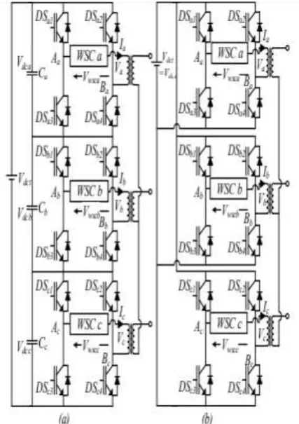
B. Three-phase configuration
through three units of single-phase transformers. These transformers are used to provide isolation between the three-phase outputs of the converter and to match the ac and dc voltage levels [34]. As three separate transformers are used for each phase, it eases the shipment of transformers and also reduces the spare holding requirements. These are important considerations for HVDC applications [34]. As the series-HBHMC uses 1/3 of Vdct for each phase, it is more suitable for the applications like tapping of existing HVDC lines [36], where the dc-link voltage is high and current is low. The parallel-HBHMC uses full Vdct for each phase. Hence it is more suitable for applications requiring high current with low dc-link voltage like back to back HVDC system [32] and medium voltage dc transmission system [37].
C. Modes of operation The normal steady-state HBHMC operation can be categorized into two operating modes depending on the MHBC switching states as explained below. 1) Powering Mode: In powering mode, the output of MHBC is a square wave and the WSC is responsible to obtain the multilevel output voltage waveform from the output of HBHMC. In this case, the dc-link is connected to load through WSC and it supplies power to both WSC and load. This mode is termed as powering mode because the energy is exchanged between the dc-link and the ac system. In this mode, for the positive half-cycle of output voltage DSx1 is on and DSx2 is off, and for the negative half-cycle DSx1 is off and DSx2 is on. Here, x represents phase-a, b, or c. In this mode, the phase-x converter output voltage (Vx) depends on the perphase dc-link voltage (Vdcx) and the voltage across WSC (Vwscx). For series-HBHMC, Vdcx = Vdct/3 and for parallel-HBHMC, Vdcx = Vdct. The equivalent circuit schematics for
positive and negative half-cycles of the powering mode are shown in Figs.
4. RESULTS
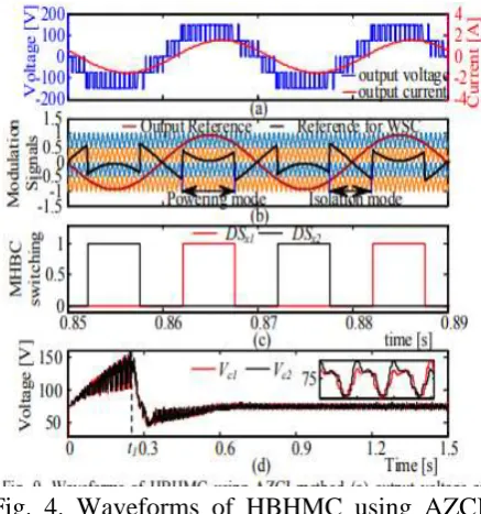
Fig. 3 Waveforms of HBHMC using HCI method (a) Output voltage and current waveforms, and (b) Modulation signals for HCI method, (c) switching signals of MHBC, and (d) individual capacitor voltages of WSC.
(d) Individual capacitor voltages of wave shaping circuit
5.CONCLUSION
This paper proposes an H-bridge hybrid multilevel converter topology, HBHMC, for HVDC applications. The proposed converter is a dc fault tolerant hybrid topology, which uses cascaded FBSMs (i.e. WSC) connected to the output of the MHBC. The WSC helps in generating the multilevel voltage waveform at the HBHMC output. For a three-phase circuit, three such HBHMCs can be connected in series on the dc side to handle a high dc-link voltage. Similarly, they can instead be connected in parallel across the dc-link for high dc current. In this paper, the basic operation of HBHMC and new modulation techniques to balance the capacitor voltages of HBHMC by appropriately selecting an operating mode (isolation mode: HCI and AZCI methods) are presented. The suggested voltage control methods are simple and easy to implement. Moreover, both the HCI and the AZCI methods are designed in a way that the MHBC always operates at the fundamental frequency to reduce the switching losses of converter. Further, the AZCI method offers more advantages than the HCI method, such as, smaller value of submodules capacitance and ability to operate in the overmodulation mode. Some of the other prominent advantages of the proposed converter are: (i) extra degree of freedom for capacitor voltage balancing, (ii) fewer semiconductor devices and capacitors in series-HBHMC, (iii) higher dc-link utilization in parallel-HBHMC, and (iv) inherent dc fault current blocking capability. Simulation and experimental studies are performed to validate the proposed converter topology and capacitor voltage control methods.
REFERENCES