Localization Techniques and Their Challenges in
Underwater Wireless Sensor Networks
Mukesh Beniwal, Rishipal Singh Department of Computer Science and Engineering,
Guru Jambheshwar University of Science & Technology, Hissar, India
Abstract
--
Underwater Wireless Sensor Networks (UWSNs) are widely used to explore aqueous environment. In UWSN, determining the location of sensor nodes is a critical issue. Sensed data is meaningful only when sensing node is localized. There are many techniques available for localization in Wireless Sensor Network (WSN) but they are not applicable in UWSN. GPS signals cannot be used underwater for localization. Underwater communication is based on acoustic waves. This paper explores the different localization schemes available for UWSN and challenges to meet the localization issue. Node mobility, high propagation delay, time synchronization and high bit error rate are the main challenges that need to be addressed.Keywords- Underwater Wireless Sensor Network, Localization, Acoustic Communication.
I.INTRODUCTION
Underwater Sensor Networks (USNs) are a promising solution for exploring aqueous environment. Many applications such as ecosystem monitoring, seismic monitoring for oil extraction [1], pollution and water quality control, disaster prevention, military surveillance etc. uses USNs. USNs use acoustic signals for communication because radio waves get attenuated in underwater environment. Large propagation delay, high bit error rate, low data rate and low bandwidth are characteristics of acoustic communication [3].
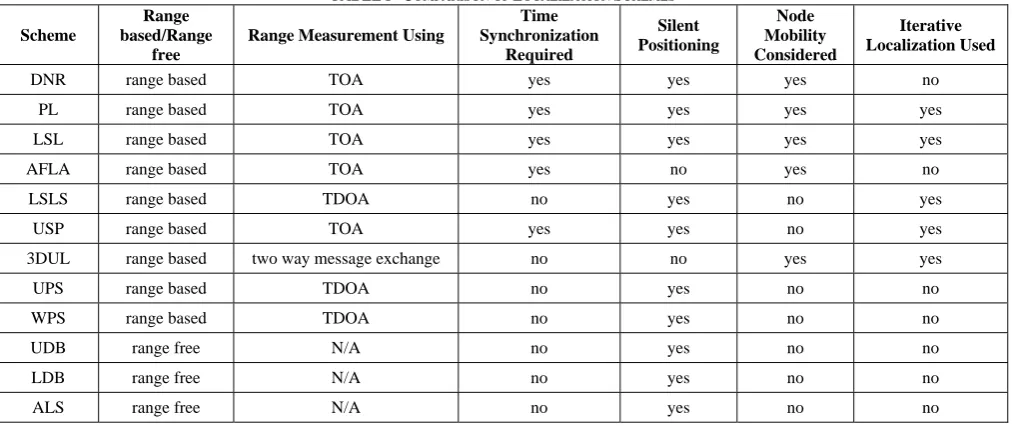
Architecture of underwater network is application dependent. A general architecture of underwater sensor network is shown in Fig. 1. UWSN consists of sensor nodes, supernodes, base station, autonomous underwater vehicles (AUV), remotely operated vehicles (ROV) controlled by a base station etc. Sensor nodes collect data by monitoring underwater deployment area and use acoustic link to relay that data to sea floor base station. Base station uses acoustic signals to communicate with underwater nodes and use radio signals to relay data to a user station for processing. Sensor nodes should be energy efficient because power management is a critical issue in underwater network.
There are many critical issues in underwater network like energy efficiency, time synchronization, localization, routing protocol etc. need to be resolve. Localization of sensor nodes is necessary because sensed data is only meaningful when sensor node is localized. There are many localization schemes proposed for wireless sensor network but these cannot be directly applied to USN because
characteristics of USN are different from that of WSN. As GPS uses radio waves which get attenuated underwater, so it cannot be used for underwater localization. In this paper, we discussed different localization schemes proposed for USN. These localization schemes are divided into two categories: Range-based schemes and Range-free schemes [4], [5]. These schemes are discussed separately.
Fig. 1 Common architecture of UWSN
Rest of paper is organized as: In section 2, challenges faced in USN localization are discussed. Section 3 contains description of based schemes. In section 4, range-free schemes are described. Section 5 contains comparison of localization schemes and finally section 6 concludes the paper.
II.CHALLENGES IN UNDERWATER LOCALIZATION
Main challenges [2] in underwater localization are:
A. Node Deployment
Deployment of sensor and reference nodes is difficult and costly in deep sea environment.
B. Node mobility
Underwater nodes get drifted by underwater current and others activities. Speed of current is time variable and difficult to predict. If a node get moved during localization process, its position estimation gone wrong.
Strength of acoustic signal gets affected by many factors like Doppler shift, multipath propagation, attenuation and external noise. RSSI based localization schemes needs to consider all these factors as they can decrease the performance of the scheme.
D. Time Synchronization
Many localization schemes assume that nodes are synchronized. Time synchronization is difficult to achieve in underwater scenario due to long propagation delay and variable sound speed. As radio signals cannot propagate underwater, so GPS service is also not available.
E. Variation in Sound Speed
Localization schemes assume constant sound speed but it is variable and depends on temperature, pressure and salinity. Variations in any one of these factors alter the sound speed. It may introduce error in distance estimation and accuracy of the scheme may decrease.
F.
Acoustic channel characteristicsSpeed of sound in water is five orders of magnitude lower than radio wave. So propagation delay is higher. Bandwidth is limited and it depends on transmission range and frequency. Data rate is low compared to radio and bit error rate is higher.
III.RANGE-BASED LOCALIZATION SCHEMES
Range-based localization schemes use range or bearing information for position estimation. These may use Time of Arrival (TOA), Time Difference of Arrival (TDOA) or Received Signal Strength Indicator (RSSI) for distance estimation. In most of cases, TOA is used. Location of some nodes in network is known in advance which are called anchor node or reference node. These are used to localize other unlocalized nodes in the network. First of all, distance is measured between sensor node and some anchor nodes. Then these distance measurements are used to find node’s position coordinates. To find d coordinates, d+1 distance measurements are required.
In paper [11], an anchor free localization algorithm (AFLA) is proposed. In this scheme, no anchor nodes are deployed. Sensor nodes are connected to fixed anchors by cable at sea bottom to avoid them to move away from monitoring area. So movement of nodes is active restricted. It is self localization algorithm that makes use of relationship of adjacent nodes for position estimation. Node mobility is considered and it is applicable to both static and dynamic environment.
A hierarchical localization approach (LSL) for large scale 3D network is proposed in [10]. The whole localization process is divided into two subprocesses: anchor node localization and ordinary node localization. Any existing technique can be used for anchor node localization. For ordinary node localization, a distributed approach is used that integrated 3D Euclidean distance estimation with recursive location estimation method.
Fig. 2 Nodes deployment in hierarchical localization [10]
There are three types of nodes: surface buoy, anchor node and ordinary node as shown in Fig. 2. Surface buoys get their location through GPS and helps in anchor nodes localization. Anchor nodes in turn are used to localize ordinary nodes. High localization coverage with low communication overhead can be achieved by this scheme.
A time synchronization free localization scheme (LSLS) for large scale UWSN is proposed in paper [14]. Three surface buoys are deployed that can hear each other. It relies on time difference of arrival measured at a sensor node from three anchor nodes that can hear each other. Reactive beaconing is used for time synchronization. Sensor node projects anchor nodes to its horizontal plane and use trilateration technique to find its coordinates. An iterative procedure is followed in which localized nodes become reference nodes in next round to maximize coverage. Effect of variable sound speed on the scheme is evaluated. High node density is required for large area coverage.
A distributed bilateration projection based method for 3D UWSN called underwater sensor positioning (USP) is introduced in paper [15]. In it, 3D localization problem is transformed to its 2D counterpart by employing depth information of sensor nodes as shown in Fig. 3. The authors proved that nondegenerative projection preserves network localizability and all k-lateration techniques are equivalent. Bilateration and iterative localization is used to localize all nodes in 3D network with the help of three surface buoys. A node is localizable in 2D plane if it is localizable in 3D plane. Bilateration can localize more nodes than can be localized by trilateration.
Paper [16] introduced underwater positioning system (UPS) scheme. It is a silent positioning scheme that does not require time synchronization among nodes. Four reference nodes including one deployed underwater are used. Time difference of arrival from reference nodes is used for range measurement by sensor nodes. There exists infeasible region in coverage area that contains some nodes which cannot be uniquely localized even if they are close to reference nodes. An extended version of UPS called wide coverage positioning (WPS) scheme is explored in [17]. Five reference nodes are used in WPS to avoid the problem of infeasible region in UPS. Beaconing from fifth reference node is used only when node cannot be uniquely localized by four reference nodes to avoid extra latency and communication overheads. Performance of WPS is worsted than UPS but it achieves unique localization with high probability.
Dive and Rise (DNR) approach is proposed in [8]. Dive and Rise beacons are used which learn their coordinates using GPS when floating on sea surface and then dive in sea to a certain depth and rise again. During this, message containing their location and time are broadcasted to the sensor nodes. Sensor nodes passively listen to DNR message beacons and calculate their location after getting three or more messages. It is a silent positioning scheme and uses TOA for distance measurement. A simple mobility model is used for taken into account the node mobility.
Multistage localization using mobile beacon (PL) is proposed in paper [9]. Here DNR scheme is integrated with iterative localization. DNR beacons dive only to a small depth rather than to cover whole monitoring area in this scheme. A node localized by mobile beacons becomes new anchor node and helps to localize other nodes if it lies below maximum dive depth of mobile beacons. Meandering current mobility (MCM) model is used to consider node mobility [19].
A three dimensional underwater localization (3DUL) algorithm is explored in [6]. Localization process is divided into two phases: 1. ranging and 2. projection and dynamic trilateration. During ranging, estimated sound speed and two ways message are used for distance measurement between sensor node and three neighboring anchor nodes. During 2nd phase, three anchor nodes are projected to plane of to be localizing node. If virtual anchor plane is robust, then trilateration is used to find location. Iterative localization is used to cover large area. Error propagation is avoided by using robustness condition for virtual plane.
IV.RANGE-FREE LOCALIZATION SCHEMES
Range free schemes do not use range or bearing information i.e. TOA, TDOA, RSSI is not used for localization in these schemes. These are simple techniques and provide coarse-grained location estimation for underwater nodes.
An area localization scheme (ALS) proposed in [7] estimates node’s location in a certain area rather than exact location. Each reference node sends acoustic signals at different power level. So area is divided in smaller region
based on different power level of reference nodes. Spherical propagation model is used for acoustic signals. Sensor nodes record the minimum power level received for each reference node and send this information to a central server. Central server find the region in which sensor node reside based on that information. Granularity of the scheme is determined by number of power level used by the reference nodes. Main limitations of this scheme are: 1.It is centralized. 2. Coverage is determined by communication range of reference nodes and 3. It does not provide exact position coordinates.
In paper [12], a localization scheme using directional beacons (UDB) is provided. An AUV with directional antenna moves over a predefined route and sends directional signals at some angle toward sensor nodes as shown in Fig. 4.
Fig. 4 AUV sending Directional Beacons [12]
Sensor nodes passively listen these signals and localize themselves. It is an energy efficient technique because sensor nodes are only receiving the mobile beacons. Time synchronization among nodes is not required. Sensor nodes are assumed static and coordinates of AUV at two time instance are required for finding position of nodes. Boundary of monitoring area should be known at deployment time for designing AUV route.
TABLE I COMPARISON OF LOCALIZATION SCHEMES
Scheme
Range based/Range
free
Range Measurement Using
Time Synchronization
Required
Silent Positioning
Node Mobility Considered
Iterative Localization Used
DNR range based TOA yes yes yes no
PL range based TOA yes yes yes yes
LSL range based TOA yes yes yes yes
AFLA range based TOA yes no yes no
LSLS range based TDOA no yes no yes
USP range based TOA yes yes no yes
3DUL range based two way message exchange no no yes yes
UPS range based TDOA no yes no no
WPS range based TDOA no yes no no
UDB range free N/A no yes no no
LDB range free N/A no yes no no
ALS range free N/A no yes no no
V.COMPARISON OF LOCALIZATION SCHEMES
Comparison of different localization schemes discussed in this paper is shown in Table II. These are compared on the basis of time synchronization, node mobility, range measurement etc. Nodes should be synchronized if TOA is used for range measurement. Silent positioning schemes are useful in minimizing communication overheads because sensor nodes only receive data and not transmit any data for localization. Transmission consumes more energy rather than receiving. To maximize coverage, recursive localization is useful. If localization of nodes is needed only for routing protocol, then any of range-free schemes can be used. A localization scheme is chosen according to the need of the application. A performance based comparison of DNR, PL and LSL schemes is done in paper [18] using simulation.
VI.CONCLUSION
Localization of nodes in UWSN is a challenging task and it is necessary for data tagging, for routing protocols etc. This paper presented a survey of different localization schemes that is applicable to underwater scenario. These schemes are classified into two categories: range-based schemes and range-free-schemes. Localization schemes of each category are discussed. A number of challenges faced during localization are also presented. At last, localization schemes are compared. A localization scheme should have large coverage, low communication overheads, high accuracy and low deployment cost. A localization scheme is chosen according to the requirement of the application.
REFERENCES
[1] J. Heidemann, W. Ye, J. Wills, A. Syed, and Y. Li, “Research
challenges and applications for underwater sensor networking,” in
Proc. IEEE Wireless Communications and Networking Conference,
vol.1, pp. 228–235, Apr. 2006.
[2] J.-H. Cui, J. Kong, M. Gerla, and S. Zhou, “The challenges of
building mobile underwater wireless networks for aquatic
applications,” IEEENetwork, vol. 20, no. 3, pp. 12–18, May 2006.
[3] N.-S. Ismail, L. A. Hussein, and S. H. Ariffin, “Analyzing the
performance of acoustic channel in underwater wireless sensor
network (UWSN),” in Proc. IEEE Fourth Asia International
Conference on Mathematical /Analytical Modelling and Computer
Simulation (AMS), pp. 550–555, 2010.
[4] V. Chandrasekhar, W. K. Seah, Y. S. Choo, and H. V. Ee,
“Localization in underwater sensor networks: survey and
challenges,” in Proc. the 1st ACM international workshop on
Underwater networks, pp. 33–40, Sep. 2006.
[5] H.-P. Tan, R. Diamant, W. K. Seah, and M. Waldmeyer, “A survey
of techniques and challenges in underwater localization,” Ocean
Engineering, vol. 38, no. 14, pp. 1663–1676, Oct. 2011.
[6] M. T. Isik and O. B. Akan, “A three dimensional localization
algorithm for underwater acoustic sensor networks,” IEEE
Transactions on Wireless Communications, vol. 8, no. 9, pp. 4457–
4463, 2009.
[7] V. Chandrasekhar and W. Seah, “An area localization scheme for
underwater sensor networks,” in Proc.OCEAN -Asia Pacific, IEEE,
pp.1–8, 2007.
[8] M. Erol, L. F. Vieira, and M. Gerla, “Localization with Dive’N’Rise
(DNR) beacons for underwater acoustic sensor networks,” in Proc.
the second ACM workshop on Underwater networks, pp. 97–100,
Sep. 2007.
[9] M. Erol, F. L. M. Vieira, A. Caruso, F. Paparella, M. Gerla, and S.
Oktug, “Multi stage underwater sensor localization using mobile
beacons,” in Proc. Second International Conference on Sensor
Technologies and Applications, SENSORCOMM, IEEE, pp. 710–
714, 2008.
[10] Z. Zhou, J.-H. Cui, and S. Zhou, “Efficient localization for
large-scale underwater sensor networks,” Ad Hoc Networks, vol.
8, no. 3, pp. 267–279, May 2010.
[11] Y. Guo and Y. Liu, “Localization for anchor- free underwater sensor
networks,” Computers & Electrical Engineering, vol. 39, no. 6, pp. 1812–1821, Aug. 2013.
[12] H. Luo, Y. Zhao, Z. Guo, S. Liu, P. Chen, and L. M. Ni, “Udb:
using directional beacons for localization in underwater sensor
networks,” in Proc.14th IEEE International Conference on Parallel
and Distributed Systems, ICPADS, pp.551–558, Dec. 2008.
[13] H. Luo, Z. Guo, W. Dong, F. Hong, and Y. Zhao, “LDB:
Localization with Directional Beacons for Sparse 3D Underwater
Acoustic Sensor Networks,” Journal of networks, vol. 5, no. 1, pp.
28-38, Jan. 2010.
[14] W. Cheng, A. Thaeler, X. Cheng, F. Liu, X. Lu, and Z. Lu,
“Time-synchronization free localization in large scale underwater acoustic
sensor networks,” in Proc.29th IEEE International Conference on
Distributed Computing Systems Workshops, ICDCS Workshops, pp.
80–87, 22-26 June 2009.
[15] A. Y. Teymorian, W. Cheng, L. Ma, X. Cheng, X. Lu, and Z. Lu,
“3D underwater sensor network localization,” IEEE Transactions on
[16] X. Cheng, H. Shu, Q. Liang, and D.-C. Du, “Silent positioning in
underwater acoustic sensor networks,” IEEE Transactions on
Vehicular Technology, vol. 57, no. 3, pp. 1756–1766, 2008.
[17] H. Tan, A. F. Gabor, Z. A. Eu, and W. K.-G. Seah, “A Wide
Coverage Positioning System (WPS) for Underwater Localization,”
in Proc. IEEE International Conference on Communications (ICC),
pp. 1–5, 23-27 May 2010.
[18] M. Erol-Kantarci, S. Oktug, L. Vieira, and M. Gerla, “Performance
evaluation of distributed localization techniques for mobile
underwater acoustic sensor networks,” Ad Hoc Networks, vol. 9, no.
1, pp. 61–72, Jan. 2011.
[19] A. Caruso, F. Paparella, L. F. M. Vieira, M. Erol, and M. Gerla,
“The Meandering Current Mobility Model and its Impact on
Underwater Mobile Sensor Networks,” in Proc. IEEE INFOCOM,
The 27th Conference on Computer Communications, pp. 221-225,
![Fig. 2 Nodes deployment in hierarchical localization [10]](https://thumb-us.123doks.com/thumbv2/123dok_us/7837277.1298896/2.595.317.532.616.738/fig-nodes-deployment-hierarchical-localization.webp)