A Fuzzy Adaptive Pi Controller Based DTC
Induction Motor Drive
S.Sridhar
1, Dr.N.Yadaiah
2, C.Anil Kumar
3Assistant Professor, Dept. of EEE, JNTUA College of Engineering, Ananthapuramu, Andhra Pradesh,India1 Professor, Dept. of EEE, JNTUH College of Engineering, Kukatpally, Hyderabad, Andhra Pradesh, India2
Dept. of EEE, JNTUA College of Engineering, Ananthapuramu, Andhra Pradesh, India3
ABSTRACT: Direct torque control is used over Field oriented control (FOC) because of its simple control structure
and in steady state, transient state operating conditions shows better torque control. Direct torque control has the advantages like robust and fast torque responsive. But in low speed operation stator flux estimation raises difficulty due to improper working of an open loop voltage model observer and existence of an open loop integrator. Hence an adaptive flux observer is implemented which eliminates open loop integration, therefore improves the machine performance by minimizing stator current distortions, fast response of rotor speed, stator flux electro-magnetic torque without ripple, constant switching frequency. Voltage distortions are modelled using a non-linear inverter. In this paper a novel approach is seen where fuzzy logic controller is adapted which overcomes high torque ripples and improves the system performance. Simulation results are carried out for the proposed system.
KEYWORDS:Direct torque control, Adaptive flux observer, Lyapunov theory, Space vector modulation (SVM),
Non-linear inverter model, Fuzzy logic controller.
I.INTRODUCTION
A mature technology owing to controlling of induction motors have developed in absence of speed sensor in past few years. A well-known method used for the control of ac drives is Direct torque control (DTC). Direct torque control is a well-known strategy for ac motor control method which yields fast torque response as it employs instantaneous torque which was developed by Japanese and German researchers more than a decade ago. It attained a great interest as it works even at zero speed which is very significant in industrial contribution. Electro-magnetic torque and flux linkage are directly and independently controlled by inverter switching modes. The flux linkage and electro-magnetic torque errors are restricted with in torque and flux hysteresis band, to get fast torque response, low harmonic losses and low inverter switching frequency. To reduce torque ripple [1] numerous techniques have been developed.
An adaptive flux observer with space vector modulation (SVM) technique is used to reduce the ripples to obtain constant switching frequency to the inverter and a torque ripple with reduced flux. DTC-SVM scheme is developed to reduce the ripples and also which an advantage of minimizing stator current distortions, fast response of rotor speed, stator flux electro-magnetic torque without ripples and constant switching frequency is obtained. In this paper fuzzy logic controller is adapted to improvise the system performance as an innovative technology with engineering expertise’s and enhances conventional system by reducing torque ripple and constant switching frequency is maintained.
II. LITERATURE SURVEY
D. Cascade I, G. Grandi, G. Serra, A. Tani [1] discuss about the flux and hysteresis band of direct torque control. This paper shows the working of induction motor for which the motor is been effected by torque ripples and remedies to reduce the torque ripples are been discussed by suggesting the developed techniques.
III. MATHAMATICAL MODEL FOR ADAPTIVE FLUX OBSERVER (AFO)
An adaptive flux observer (AFO) for speed estimation of sensor less induction motor drives is one of the methods based on machine model. The advantages are fast response of rotor speed, improving the machine performance by minimizing stator current distortions, stator flux electro-magnetic torque without ripple, eliminating open loop integration and constant switching frequency.
Basic flux observer: The mathematical equation of induction motor of stationary reference is given by
I s s
λ s s =
P11 P12
P21 P22
Iss
λss
+ QQ1
2 Us
s = PX + QU
s (1)
here P11, P12, P21, P22, Q1,Q2 are in appendix.
The system output is supposed where states are considered for the stator current and flux. Hence state observer is given by
X
.
S= P X + QUs+ G I s− Is (2)
here G is the gain matrix observer and values which are estimated are denoted by .
Lyapunov Theory: To make conclusions of a system about trajectories lyapunov theory is used. A lyapunovtheorm is given by a function
𝑉 ∶ 𝑅𝑛 → 𝑅
Which satisfies the conditions depending on 𝑉and 𝑉 , hence system trajectories satisfy some property and if such a function 𝑉 exists it is called a lyapunov function.
Lyapunov theory based adaptive flux observer (AFO) for speed estimation: In the observer state equations rotor speed in speed sensor less drives are treated as un-known parameters. Estimation of states and un-known parameters are applied simultaneously using an adaptive technique. Lyapunov theory gives the adaptive technique equations where state estimation error is obtained by subtracting (1) from (2).
e = P + GC e + ∆PX (3)
here
e = X − X
∆P = P − P = −∆ωr
∆ωr
σLs
J
0 0
A Lyapunov function will be
V = ete + ω
r− ωr 2/λ (4)
here λ is a positive constant. Derivative of V w.r.t time is given by
d
dt V = e
t P + GC t+ P + GC + Xt∆Pte + et∆P X − 2∆ω r
d
On equating last two terms in (5) an adaptive scheme is for speed estimating is obtained which is given by
ωr= Gω ∆Isd λLrφsq− Isd − ∆Isq λLrφsd − Isd dt (6)
hereGω is a positive constant .
Therefore according to lyapunov theory adaptive flux observer must have stable poles. On defining G values observer pole placement is achieved. By defining G values a new observer gain matrix is obtained which is given by
G1= 2QI (7)
G2= σLsQI (8)
where Q is negative gain constant gain matrix observer does not depend on rotor speed which gives stable operation over wide speed range.
By adding a simple mechanical model of the system the transient response of speed estimation can be improved. To estimate the load torque for speed estimation the derived term is
TL= −Gr ∆Isd λLrφsq − I sq − ∆Isq λLrφsd − Isd dt (9)
ωr= Np/J Te− TL + Gω ∆Isd λLrφsd − I sq − ∆Isq λLrφsd − I sd dt (10)
hereT is estimate torque, TL is estimated load torque and Gω is a positive gain. In both steady state and transient
condition modified observer has an acceptable performance.
Adaptive flux observer (AFO) for stator resistance estimation: During system operation temperature variation is inevitable hence induction motor have resistance. To include stator resistance the adaptive scheme can be extended where rotor speed, stator resistance as un-known parameters gives the stable error equation as
e = P + GC e + ∆PX + ∆P′X (11)
here
∆P′ = P − P′= −
∆Rs
σLs
I 0
−∆RsI 0
Lyapunov function is given by
V′ = ete ωr− ωr 2
/λ + Rs− Rs 2
/λ′ (12)
V′ = V + R
s− Rs
2
/λ′ (13)
Time derivative of V′ is given by
d
dt V
′ = d
dt V + X t
∆P′te + et∆P′ − 2∆RX s
d
dtRs/λ (14)
Rs = −GR I sxesx+ I syesy dt (15)
hereGR is a positive constant..
Non-Linear Inverter: For each inverter leg in a three phase voltage source inverter, the switching commands are complimentary. A logic state Ci=(i-a,b,c) for each is defined as if Ci=1 then the upper switch is turned on and the
switch in lower side is turned off and if Ci=0 then the switch in lower side is turned on and the upper switch is turned
off. There will be eight different states since there are three independent legs, so eight different voltages [2] [3] [4]. Three phase inverter fed from a dc source is shown in fig1.
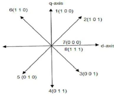
To study the developed direct torque control model performance an open loop torque control using MATLAB/Simulink is simulated. Errors are compared to generate the logic states ST and Sψin hysteresis band. Three dimensional look up
table from the instantaneous inverter switching voltage vector are obtained from three controlling signals. Conventional DTC scheme is implemented for simulation results. Two zero voltage vectors and six non zero voltage vectors are shown in fig 2. [5].
Fig 1 Three phase voltage inverter Fig 2d,q plane partition in six angular sectors
Space vector linkage for stator flux is given by
ℵs = Vs− RsIs dt (16)
Stator ohmic drop is neglected, then we have
dℵs
dt = Vs (17)
Hence in short interval time (Δt)
∆ℵs = Vs∗ ∆t (18)
HereVs is six pulse inverter voltage vector. Stator flux can be rotated quickly in any direction by applying appropriate
IV. DTC-SVM METHOD
Steady state performance of DTC method is improved by DTC-SVM strategy. Two PI regulators receives the stator flux and torque errors in the control back. Command voltage generated by the regulators impress the desired voltage and receives command voltage to the motor. Stator flux magnitude is estimated as
ℵsd = Vsd − RsIsd dt (19)
ℵsq = Vsq− RsIsq dt (20)
d-q axes flux and current components are computed to develop torque of motor. Calculation of torque component is given by
Te= 3
2 P
2 Isqℵsd− Isdℵsq (21)
Torque and flux are constrained by hysteresis controller within its band, torque and flux value are controlled[7]. Stator flux position, torque and flux errors depend on appropriate selection of voltage vector. Reducing of torque and flux error depends on selection of voltage vector. DTC-SVM method is shown in fig3
Fig 3 Block diagram of Adaptive observer with DTC-SVM
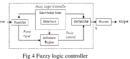
V. PROPOSED FUZZY LOGIC CONTROLLER (FLC)
Fuzzy logic controller [8] based on linguistic control strategy is a control algorithm which tries to control a system without requiring mathematical model and tries to account how to control a system with human knowledge.
Fig 4 Fuzzy logic controller
region membership functions should be narrow to achieve finer control. Faster response to the system is achieved by wider membership functions away from zero region. Adjustment of membership created after appropriate membership functions which defines behaviour of system.
Fig 5 Membership functions of input error Fig 6 Membership functions of input error change
Fig 7 Membership functions of output
VI.SIMULATION MODELS AND RESULTS
time(s) time(s)
Fig 10 Actual and estimated speed of DTC-SVM and Fuzzy DTC-SVM at 3(rad/s)
From fig 10 at low speed i.e 3rad/s we can clearly see the reduction of ripples in actual and estimated speed curve of Fuzzy DTC-SVM as the fuzzy logic controller controls the torque ripples by reducing them which improves the system performance as it smoothens the speed curves from torque ripples.
time(s) time(s)
Fig 11 Speed estimation error of DTC-SVM and Fuzzy DTC-SVM at 3(rad/s)
From fig 11 at low speed i.e 3rad/s reduction of ripples is seen in speed estimation curve of Fuzzy DTC-SVM as the fuzzy logic controller controls the torque ripples by reducing them which improves the system performance as it smoothens the speed curves from torque ripples.
time(s) time(s)
Fig 12 Actual and estimated speed of DTC-SVM and Fuzzy DTC-SVM at 4(rad/s) during speed reversal
time(s)time(s)
Fig 13 Stator resistance estimation of DTC-SVM and Fuzzy DTC-SVM
Fig 13shows the estimation of stator resistance at 0.5 ohms where the drive performance is improved in Fuzzy DTC-SVM system as the fuzzy logic controller minimizes the ripples.
time(s)time(s)
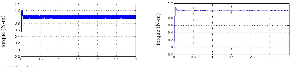
Fig 14Torque characteristics of DTC-SVM and Fuzzy DTC-SVM
VII. CONCLUSION
In this paper a novel fuzzy logic controller is proposed with adaptive flux observer to reduce the torque ripples of conventional DTC system. Present system improves the system performance as the fuzzy logic controller determinates the desired amplitude of torque hysteresis band.Hence even at low speed it provides minimum switching loss and noise.
REFERENCES
[1] D. Cascade I, G. Grandi, G. Serra, A. Tani, “ Effects of flux and torque hysteresis band amplitude in direct torque control of induction machines”, in 20th international conference on industrial electronics control and instrumentation (IECON), Vol.1, pp 299-304, 1994.
[2] J. Holtz and J. Quan “Sensor less vector control of induction motors at very low speed using a non linear inverter model and parameter identification” IEEE Trans Industry Application, Vol.38.no.4, pp 1087-1095, Jul/Aug 2002.
[3] Y.S Lai and J.H Chen, “ A new approach to direct torque control of induction motor drives for constant inverter switching frequency and torque ripple reduction” ,IEEE Trans Energy Convers Vol.16, No.3, pp 220-227, sep 2001.
[4] C. Lascu, I. Boldea and F. Blaabj erg, “ A modified DTC for IM sensor less drive”, IEEE Trans Applicat, Vol.36, No1,pp122-130, Jan 2000. [5] Jagadish H. Pujar and S.F Kodad, “ Direct Fuzzy control of an AC Drive”, Proceedings of international conference on advances in computing,
control and Tele communication technologies, pp 275-277, 2009.
[6] Y. Xia and W. Oghanna, “Study on fuzzy control of induction machine with Direct torque control approach”, proceedings of IEEE international symposium on industrial Electronics, Vol 2, pp 625-630,1997.
[7] M. Depenbrok, “ Direct self control (DSC) of Inverter-Fed Induction Machine”, IEEE on Power Electronics, Vol. 3,No.4, pp 420-429,1988. [8] Jia-Qiang Yang and Jin Huang, “ Direct torque control system for Induction Motors with Fuzzy speed Pi regulator”, proceedings of the
International Conference on Machine learning and Cybernetics, Vol.2, pp. 778-783, 2005.
[9] Gilberto c d souce, Bimal K Bose, “ A fuzzy set theory based control of phase controlled converter DC motor drive”, IEEE Transactions on Power delivery, vol.14,no.2, july 2011.